Motherboard DIY Troubleshooting Guide
Page 3
Features Contents Notices v Safety information vi About this guide vii ASUS contact information viii P4S800 specifications summary ix Chapter 1: Product introduction 1.1 Welcome 1-2 1.2 Package contents 1-2 1.3 Motherboard components 1-3 1.4 Special Features 1-6 1.5 Motherboard layout 1-8 ... for this motherboard 1-15 1.11 Jumpers 1-16 1.12 Connectors 1-18 Chapter 2: BIOS information 2.1 Managing and updating your BIOS 2-2 2.1.1 Using ASUS EZ Flash to update the BIOS 2-2 2.1.2 Using AFLASH to update the BIOS 2-3 2.1.3 CrashFree BIOS 2 feature 2-6 2.2 BIOS Setup program 2-7 iii
Features Contents Notices v Safety information vi About this guide vii ASUS contact information viii P4S800 specifications summary ix Chapter 1: Product introduction 1.1 Welcome 1-2 1.2 Package contents 1-2 1.3 Motherboard components 1-3 1.4 Special Features 1-6 1.5 Motherboard layout 1-8 ... for this motherboard 1-15 1.11 Jumpers 1-16 1.12 Connectors 1-18 Chapter 2: BIOS information 2.1 Managing and updating your BIOS 2-2 2.1.1 Using ASUS EZ Flash to update the BIOS 2-2 2.1.2 Using AFLASH to update the BIOS 2-3 2.1.3 CrashFree BIOS 2 feature 2-6 2.2 BIOS Setup program 2-7 iii
Motherboard DIY Troubleshooting Guide
Page 4
Safeguards Contents 2.2.1 BIOS menu bar 2-7 2.2.2 Legend bar 2-8 2.3 Main Menu 2-8 2.3.1 Primary and Secondary Master/Slave 2-10 2.3.2 Keyboard Features 2-13 2.4 Advanced Menu 2-13 2.4.1 Chip Configuration 2-16 2.4.2 I/O Device Configuration 2-18 2.4.3 PCI ... 2-23 2.6 Boot Menu 2-24 2.7 Exit Menu 2-26 Chapter 3: Software support 3.1 Install an operating system 3-2 3.2 Support CD information 3-2 3.2.1 Running the support CD 3-2 3.2.2 Drivers menu 3-3 3.2.3 Utilities menu 3-3 3.2.4 ASUS Contact Information 3-4 3.3 Software information 3-4 3.3.1 ASUS Instant Music 3-4 iv
Safeguards Contents 2.2.1 BIOS menu bar 2-7 2.2.2 Legend bar 2-8 2.3 Main Menu 2-8 2.3.1 Primary and Secondary Master/Slave 2-10 2.3.2 Keyboard Features 2-13 2.4 Advanced Menu 2-13 2.4.1 Chip Configuration 2-16 2.4.2 I/O Device Configuration 2-18 2.4.3 PCI ... 2-23 2.6 Boot Menu 2-24 2.7 Exit Menu 2-26 Chapter 3: Software support 3.1 Install an operating system 3-2 3.2 Support CD information 3-2 3.2.1 Running the support CD 3-2 3.2.2 Drivers menu 3-3 3.2.3 Utilities menu 3-3 3.2.4 ASUS Contact Information 3-4 3.3 Software information 3-4 3.3.1 ASUS Instant Music 3-4 iv
Motherboard DIY Troubleshooting Guide
Page 9
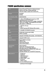
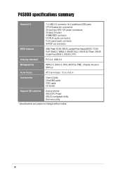
... 10/100 Mbps LAN controller + VIA VT6103 PHY Integrated 6 USB 2.0 ports Support S/PDIF out interface ASUS EZ Flash ASUS Instant Music Lite ASUS CrashFree BIOS 2 ASUS Jumperfree ASUS C.P.R. (CPU Parameter Recall) CPU, Memory and AGP Voltage adjustable SFS (Stepless Frequency Selection) from 100Mhz up...USB 1.1 ports 1 x RJ-45 port 1 x SPDIF-out port Line In/Line Out/Microphone ports (continued on the next page) ix P4S800 specifications summary CPU Chipset Front Side Bus (FSB) Memory Expansion slots IDE Audio LAN USB 2.0 Special Features Overclocking Features Rear panel I/O Socket 478...
... 10/100 Mbps LAN controller + VIA VT6103 PHY Integrated 6 USB 2.0 ports Support S/PDIF out interface ASUS EZ Flash ASUS Instant Music Lite ASUS CrashFree BIOS 2 ASUS Jumperfree ASUS C.P.R. (CPU Parameter Recall) CPU, Memory and AGP Voltage adjustable SFS (Stepless Frequency Selection) from 100Mhz up...USB 1.1 ports 1 x RJ-45 port 1 x SPDIF-out port Line In/Line Out/Microphone ports (continued on the next page) ix P4S800 specifications summary CPU Chipset Front Side Bus (FSB) Memory Expansion slots IDE Audio LAN USB 2.0 Special Features Overclocking Features Rear panel I/O Socket 478...
Motherboard DIY Troubleshooting Guide
Page 10
P4S800 specifications summary Internal I /O shield Support CD contents Device drivers ASUS PC Probe ASUS LiveUpdate Utility Anti-virus utility * Specifications are subject to change without notice. Industry standard PCI 2.2, USB 2.0 Manageability WfM 2.0, DMI 2.0, WOL/WOR by PME, ... 20-pin/4-pin ATX 12V power connectors Chassis intrusion GAME/MIDI connector CD/AUX audio connectors Front panel audio connector S/PDIF out connector BIOS features 2Mb Flash ROM, ASUS JumperFree,Award BIOS, TCAV, PnP, DMI2.0, WfM2.0, SM BIOS2.3, ASUS EZ Flash, ASUS CrashFree BIOS 2, ASUS C.P.R. x
P4S800 specifications summary Internal I /O shield Support CD contents Device drivers ASUS PC Probe ASUS LiveUpdate Utility Anti-virus utility * Specifications are subject to change without notice. Industry standard PCI 2.2, USB 2.0 Manageability WfM 2.0, DMI 2.0, WOL/WOR by PME, ... 20-pin/4-pin ATX 12V power connectors Chassis intrusion GAME/MIDI connector CD/AUX audio connectors Front panel audio connector S/PDIF out connector BIOS features 2Mb Flash ROM, ASUS JumperFree,Award BIOS, TCAV, PnP, DMI2.0, WfM2.0, SM BIOS2.3, ASUS EZ Flash, ASUS CrashFree BIOS 2, ASUS C.P.R. x
Motherboard DIY Troubleshooting Guide
Page 14
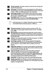
.../1.44M/2.88M floppy disk drive, a multi-mode parallel port, two serial ports, a GAME port, the mouse and keyboard interface and the BIOS Flash ROM interface. 11 Flash ROM. The SiS® 648FX provides the processor interface with 800/533/400 MHz frequency, system memory interface... at least 1A on the motherboard. The chipset supports a highperformance floppy disk controller for the floppy disk drive. This 2Mb firmware contains the programmable BIOS program. 12 Standby power LED. 1 ATX 12V connector. Both the primary (blue) and secondary (black) connectors are slotted to 1 DIMM only...
.../1.44M/2.88M floppy disk drive, a multi-mode parallel port, two serial ports, a GAME port, the mouse and keyboard interface and the BIOS Flash ROM interface. 11 Flash ROM. The SiS® 648FX provides the processor interface with 800/533/400 MHz frequency, system memory interface... at least 1A on the motherboard. The chipset supports a highperformance floppy disk controller for the floppy disk drive. This 2Mb firmware contains the programmable BIOS program. 12 Standby power LED. 1 ATX 12V connector. Both the primary (blue) and secondary (black) connectors are slotted to 1 DIMM only...
Motherboard DIY Troubleshooting Guide
Page 16
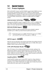
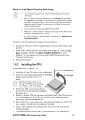
... invaded by a virus. CrashFree BIOS 2 CrashFree BIOS 2 allows users to support 3.2 GHz+ P4 CPU on 800MHz FSB, Intel® Hyper-Threading technology and DDR400 memory makes the P4S800 deliver a full-value, high-performance solution for an optional ROM. 1-6 Chapter 1: Product introduction The ASUS P4S800 motherboard is the next generation VGA... the northbridge and southbridge to 1GB/sec for a FSB800 solution. 1.4 Special Features 1.4.1 Product highlights With the SiS 648FX chipset, the ASUS P4S800 supports latest 800MHz front side bus and Intel® next generation Prescott CPU.
... invaded by a virus. CrashFree BIOS 2 CrashFree BIOS 2 allows users to support 3.2 GHz+ P4 CPU on 800MHz FSB, Intel® Hyper-Threading technology and DDR400 memory makes the P4S800 deliver a full-value, high-performance solution for an optional ROM. 1-6 Chapter 1: Product introduction The ASUS P4S800 motherboard is the next generation VGA... the northbridge and southbridge to 1GB/sec for a FSB800 solution. 1.4 Special Features 1.4.1 Product highlights With the SiS 648FX chipset, the ASUS P4S800 supports latest 800MHz front side bus and Intel® next generation Prescott CPU.
Motherboard DIY Troubleshooting Guide
Page 17
... enter Windows. (The stickers on keyboard are separately purchased.) The P4S800 Instant Music Lite feature can only be used on PS/2 keyboards. SoundMAX Digital Audio System can update BIOS before entering operating system. No more DOS-based flash utility and bootable diskette required. ASUS P4S800 motherboard user guide 1-7 Experience 5.1-channel surround sound and enhanced...
... enter Windows. (The stickers on keyboard are separately purchased.) The P4S800 Instant Music Lite feature can only be used on PS/2 keyboards. SoundMAX Digital Audio System can update BIOS before entering operating system. No more DOS-based flash utility and bootable diskette required. ASUS P4S800 motherboard user guide 1-7 Experience 5.1-channel surround sound and enhanced...
Motherboard DIY Troubleshooting Guide
Page 21
...CPU into the socket until it up the system and enter BIOS Setup (see Chapter 2). When the CPU is lifted up to compile the code. Connect the CPU fan cable to a 90°-100° angle. ASUS P4S800 motherboard user guide 1-11 This motherboard supports Intel Pentium 4...Techonology. 3. Carefully insert the CPU into the socket to install a CPU. 1. Hyper-Threading Technology is recommended that the socket lever is in BIOS before installing a supported operating system. 5. For more information on the motherboard. 2. Power up to the CPU fan connector on the side ...
...CPU into the socket until it up the system and enter BIOS Setup (see Chapter 2). When the CPU is lifted up to compile the code. Connect the CPU fan cable to a 90°-100° angle. ASUS P4S800 motherboard user guide 1-11 This motherboard supports Intel Pentium 4...Techonology. 3. Carefully insert the CPU into the socket to install a CPU. 1. Hyper-Threading Technology is recommended that the socket lever is in BIOS before installing a supported operating system. 5. For more information on the motherboard. 2. Power up to the CPU fan connector on the side ...
Motherboard DIY Troubleshooting Guide
Page 24
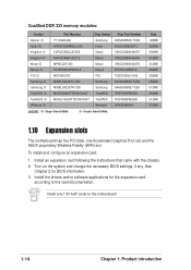
...Install an expansion card following the instructions that came with the chassis. 2. Install only 1.5V AGP cards on the system and change the necessary BIOS settings, if any. Single Sided DIMMs /D - Double Sided DIMMs Size 128MB 256MB 256MB 512MB 512MB 256MB 256MB 256MB 512MB 256MB 512MB 512MB ...1.10 Expansion slots The motherboard has five PCI slots, one Accelerated Graphics Port slot and the ASUS proprietary Wireless Fidelity (WiFi) slot. To install and configure an expansion card: 1. Turn on this motherboard! 1-14 Chapter 1: Product ...
...Install an expansion card following the instructions that came with the chassis. 2. Install only 1.5V AGP cards on the system and change the necessary BIOS settings, if any. Single Sided DIMMs /D - Double Sided DIMMs Size 128MB 256MB 256MB 512MB 512MB 256MB 256MB 256MB 512MB 256MB 512MB 512MB ...1.10 Expansion slots The motherboard has five PCI slots, one Accelerated Graphics Port slot and the ASUS proprietary Wireless Fidelity (WiFi) slot. To install and configure an expansion card: 1. Turn on this motherboard! 1-14 Chapter 1: Product ...
Motherboard DIY Troubleshooting Guide
Page 27
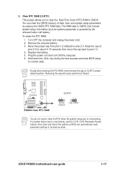
...; P4S800 Clear RTC RAM CLRTC 12 Normal (Default) 23 Clear CMOS You do not need to clear the RTC when the system hangs due to re-enter data. 2. Hold down and reboot the system so BIOS can clear the CMOS memory of date, time, and system setup parameters by the ... and enter BIOS setup to overclocking. Plug the power cord and turn ON the computer. 6. Remove the onboard battery. 3. Removing the cap will cause system boot failure! To erase the RTC RAM: 1. Turn OFF the computer and unplug the power cord. 2. For system failure due to pins 2-3. ASUS P4S800 motherboard user ...
...; P4S800 Clear RTC RAM CLRTC 12 Normal (Default) 23 Clear CMOS You do not need to clear the RTC when the system hangs due to re-enter data. 2. Hold down and reboot the system so BIOS can clear the CMOS memory of date, time, and system setup parameters by the ... and enter BIOS setup to overclocking. Plug the power cord and turn ON the computer. 6. Remove the onboard battery. 3. Removing the cap will cause system boot failure! To erase the RTC RAM: 1. Turn OFF the computer and unplug the power cord. 2. For system failure due to pins 2-3. ASUS P4S800 motherboard user ...
Motherboard DIY Troubleshooting Guide
Page 28
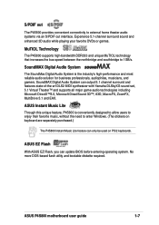
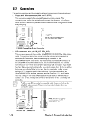
... the UltraDMA cable connector. This prevents incorrect orientation when you connect non-UltraDMA133/100/66 devices to the secondary IDE connector. P4S800 ® NOTE: Orient the red markings (usually zigzag) on the floppy ribbon cable to PIN 1. It is recommended that...install two hard disks, you have more than two UltraDMA133/100/66 devices, purchase another for the jumper settings. BIOS supports specific device bootup. SEC_IDE PRI_IDE P4S800 IDE Connectors 1-18 PIN 1 Chapter 1: Product introduction 1.12 Connectors This section describes and illustrates the internal connectors...
... the UltraDMA cable connector. This prevents incorrect orientation when you connect non-UltraDMA133/100/66 devices to the secondary IDE connector. P4S800 ® NOTE: Orient the red markings (usually zigzag) on the floppy ribbon cable to PIN 1. It is recommended that...install two hard disks, you have more than two UltraDMA133/100/66 devices, purchase another for the jumper settings. BIOS supports specific device bootup. SEC_IDE PRI_IDE P4S800 IDE Connectors 1-18 PIN 1 Chapter 1: Product introduction 1.12 Connectors This section describes and illustrates the internal connectors...
Motherboard DIY Troubleshooting Guide
Page 33
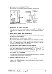
...the system power. • Hard Disk Activity Lead (2-pin IDE_LED) This connector supplies power to light up when you turn on the BIOS or OS settings. P4S800 System Panel Connectors • System Power LED Lead (3-1 pin PLED) This 3-1 pin connector connects to the primary or secondary IDE connector... system is instantly decreased to save power and to expand the life of any device connected to the system power LED. ASUS P4S800 motherboard user guide 1-23 The LED lights up . System panel connector (20-pin PANEL) This connector accommodates several system front panel functions.
...the system power. • Hard Disk Activity Lead (2-pin IDE_LED) This connector supplies power to light up when you turn on the BIOS or OS settings. P4S800 System Panel Connectors • System Power LED Lead (3-1 pin PLED) This 3-1 pin connector connects to the primary or secondary IDE connector... system is instantly decreased to save power and to expand the life of any device connected to the system power LED. ASUS P4S800 motherboard user guide 1-23 The LED lights up . System panel connector (20-pin PANEL) This connector accommodates several system front panel functions.
Motherboard DIY Troubleshooting Guide
Page 35
Chapter 2 This chapter tells how to change system settings through the BIOS Setup menus. BIOS information Detailed descriptions of the BIOS parameters are also provided.
Chapter 2 This chapter tells how to change system settings through the BIOS Setup menus. BIOS information Detailed descriptions of the BIOS parameters are also provided.
Motherboard DIY Troubleshooting Guide
Page 36
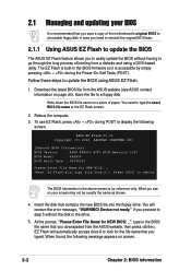
... the long process of paper. if you downloaded from the ASUS website (see on screen. 2-2 Chapter 2: BIOS information Download the latest BIOS file from the ASUS website, then press . ASUS EZ Flash V1.00 Copyright (C) 2002, ASUSTeK COMPUTER INC. [Onboard BIOS Information] BIOS Version : ASUS P4S800 ACPI BIOS Revision 1002 BIOS Model : P4S800 BIOS Built Date : 04/28/03 Please Enter File Name...
... the long process of paper. if you downloaded from the ASUS website (see on screen. 2-2 Chapter 2: BIOS information Download the latest BIOS file from the ASUS website, then press . ASUS EZ Flash V1.00 Copyright (C) 2002, ASUSTeK COMPUTER INC. [Onboard BIOS Information] BIOS Version : ASUS P4S800 ACPI BIOS Revision 1002 BIOS Model : P4S800 BIOS Built Date : 04/28/03 Please Enter File Name...
Motherboard DIY Troubleshooting Guide
Page 37
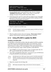
...does not work with certain memory drivers that may cause system boot failure. 8. [BIOS Information in the DOS prompt within Windows, and does not work in File] BIOS Version: P4S800 Boot Block WARNING! Press any key to the boot disk you created. The following ... the hard drive. BIOS setup must specify "Floppy" as the first item in DOS mode. Pressing N exits the EZ Flash screen and reboots the system without updating the BIOS. Press to create a bootable system disk. Press . 6. Larger numbers represent a newer BIOS file. 1. ASUS P4S800 motherboard user guide 2-3...
...does not work with certain memory drivers that may cause system boot failure. 8. [BIOS Information in the DOS prompt within Windows, and does not work in File] BIOS Version: P4S800 Boot Block WARNING! Press any key to the boot disk you created. The following ... the hard drive. BIOS setup must specify "Floppy" as the first item in DOS mode. Pressing N exits the EZ Flash screen and reboots the system without updating the BIOS. Press to create a bootable system disk. Press . 6. Larger numbers represent a newer BIOS file. 1. ASUS P4S800 motherboard user guide 2-3...
Motherboard DIY Troubleshooting Guide
Page 38
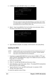
...you are sure that the new BIOS revision will solve your new BIOS and the path, for example, A:\XXX-XX.XXX, then press [Enter]. The Save Current BIOS To File screen appears. 6. Download an updated ASUS BIOS file from the Internet (WWW or FTP) (see ASUS CONTACT INFORMATION on page viii for ...details) and save to run AFLASH. The Update BIOS Including Boot Block and ESCD screen appears. 5. Save Current...
...you are sure that the new BIOS revision will solve your new BIOS and the path, for example, A:\XXX-XX.XXX, then press [Enter]. The Save Current BIOS To File screen appears. 6. Download an updated ASUS BIOS file from the Internet (WWW or FTP) (see ASUS CONTACT INFORMATION on page viii for ...details) and save to run AFLASH. The Update BIOS Including Boot Block and ESCD screen appears. 5. Save Current...
Motherboard DIY Troubleshooting Guide
Page 39
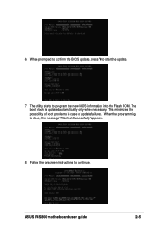
Follow the onscreen instructions to start the update. 7. 6. When prompted to confirm the BIOS update, press Y to continue. The boot block is done, the message "Flashed Successfully" appears. 8. This minimizes the possibility of boot problems in case of update failures. ASUS P4S800 motherboard user guide 2-5 The utility starts to program the new BIOS information into the Flash ROM. When the programming is updated automatically only when necessary.
Follow the onscreen instructions to start the update. 7. 6. When prompted to confirm the BIOS update, press Y to continue. The boot block is done, the message "Flashed Successfully" appears. 8. This minimizes the possibility of boot problems in case of update failures. ASUS P4S800 motherboard user guide 2-5 The utility starts to program the new BIOS information into the Flash ROM. When the programming is updated automatically only when necessary.
Motherboard DIY Troubleshooting Guide
Page 40
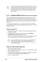
... after 30 seconds. Using the created bootable floppy disk 1. Boot using the bootable floppy disk. 2. Visit ASUS website (www.asus.com) to the boot disk. Press "Y", to update the BIOS. 2-6 Chapter 2: BIOS information If you encounter problems while updating the new BIOS, DO NOT turn off the system because this may not boot. If the...
... after 30 seconds. Using the created bootable floppy disk 1. Boot using the bootable floppy disk. 2. Visit ASUS website (www.asus.com) to the boot disk. Press "Y", to update the BIOS. 2-6 Chapter 2: BIOS information If you encounter problems while updating the new BIOS, DO NOT turn off the system because this may not boot. If the...

Motherboard DIY Troubleshooting Guide
Page 41
...Use this program. Use this last option only if the first two failed. The Flash ROM on the system chassis. It is highlighted. ASUS P4S800 motherboard user guide 2-7 This requires you can update using the provided utility described in the future. Use this utility. For example, you...the various sub-menus and make your selections among the predetermined choices. Even if you are installing a motherboard, reconfiguring your system using the BIOS Setup program so that you wish to enter Setup after POST, restart the system by pressing + + , or by turning the system ...
...Use this program. Use this last option only if the first two failed. The Flash ROM on the system chassis. It is highlighted. ASUS P4S800 motherboard user guide 2-7 This requires you can update using the provided utility described in the future. Use this utility. For example, you...the various sub-menus and make your selections among the predetermined choices. Even if you are installing a motherboard, reconfiguring your system using the BIOS Setup program so that you wish to enter Setup after POST, restart the system by pressing + + , or by turning the system ...
Motherboard DIY Troubleshooting Guide
Page 42
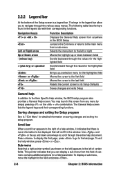
... current screen to its Setup Defaults Saves changes and exits Setup General help document. The following table lists the keys found in the BIOS Setup Jumps to the Exit menu or returns to scroll through the various setup menus. A submenu contains additional options for detailed information...menu by simply pressing or the + combination. Press to display the first page, press to go to the field and press . 2-8 Chapter 2: BIOS information To exit the help window, it indicates that a right pointer symbol (as shown on saving changes and exiting the setup program. Navigation Key(s)...
... current screen to its Setup Defaults Saves changes and exits Setup General help document. The following table lists the keys found in the BIOS Setup Jumps to the Exit menu or returns to scroll through the various setup menus. A submenu contains additional options for detailed information...menu by simply pressing or the + combination. Press to display the first page, press to go to the field and press . 2-8 Chapter 2: BIOS information To exit the help window, it indicates that a right pointer symbol (as shown on saving changes and exiting the setup program. Navigation Key(s)...


