
P4S333 English Manual
Page 2
... ERRORS OR INACCURACIES THAT MAY APPEAR IN THIS MANUAL, INCLUDING THE PRODUCTS AND SOFTWARE DESCRIBED IN IT. SPECIFICATIONS AND INFORMATION CONTAINED IN THIS MANUAL ARE FURNISHED FOR INFORMATIONAL USE ONLY, AND ARE SUBJECT TO CHANGE AT ANY TIME WITHOUT NOTICE, AND SHOULD NOT BE CONSTRUED AS A... COMMITMENT BY ASUS. Checklist E906 First Edition November 2001 Copyright © 2001 ASUSTeK COMPUTER INC. Product warranty or service will not be ...
... ERRORS OR INACCURACIES THAT MAY APPEAR IN THIS MANUAL, INCLUDING THE PRODUCTS AND SOFTWARE DESCRIBED IN IT. SPECIFICATIONS AND INFORMATION CONTAINED IN THIS MANUAL ARE FURNISHED FOR INFORMATIONAL USE ONLY, AND ARE SUBJECT TO CHANGE AT ANY TIME WITHOUT NOTICE, AND SHOULD NOT BE CONSTRUED AS A... COMMITMENT BY ASUS. Checklist E906 First Edition November 2001 Copyright © 2001 ASUSTeK COMPUTER INC. Product warranty or service will not be ...

P4S333 English Manual
Page 3
... this guide is organized viii Conventions used in this guide ix Where to find more information ix ASUS contact information x Chapter 1: Product introduction 1-1 1.1 Welcome 1-1 1.2 Package contents 1-1 1.3 Special features 1-2 1.3.1 Product highlights 1-2 1.3.2 Value-added solutions 1-3 1.4 Overview 1-4 1.4.1 Motherboard components 1-4 Chapter 2: Hardware information 2-1 2.1 Motherboard installation 2-1 2.1.1 Placement direction 2-1 2.1.2 Screw holes 2-1 2.2 Motherboard layout 2-2 2.3 Before you proceed 2-3 2.4 Central Processing Unit (CPU...
... this guide is organized viii Conventions used in this guide ix Where to find more information ix ASUS contact information x Chapter 1: Product introduction 1-1 1.1 Welcome 1-1 1.2 Package contents 1-1 1.3 Special features 1-2 1.3.1 Product highlights 1-2 1.3.2 Value-added solutions 1-3 1.4 Overview 1-4 1.4.1 Motherboard components 1-4 Chapter 2: Hardware information 2-1 2.1 Motherboard installation 2-1 2.1.1 Placement direction 2-1 2.1.2 Screw holes 2-1 2.2 Motherboard layout 2-2 2.3 Before you proceed 2-3 2.4 Central Processing Unit (CPU...

P4S333 English Manual
Page 4
... 4.5 Power Menu 4-26 4.5.1 Power Up Control 4-28 4.5.2 Hardware Monitor 4-30 4.6 Boot Menu 4-31 4.7 Exit Menu 4-33 Chapter 5: Software support 5-1 5.1 Install an operating system 5-1 5.2 Support CD information 5-1 5.2.1 Running the support CD 5-1 5.2.2 Installation menus 5-2 5.2.3 Software and drivers description 5-3 iv
... 4.5 Power Menu 4-26 4.5.1 Power Up Control 4-28 4.5.2 Hardware Monitor 4-30 4.6 Boot Menu 4-31 4.7 Exit Menu 4-33 Chapter 5: Software support 5-1 5.1 Install an operating system 5-1 5.2 Support CD information 5-1 5.2.1 Running the support CD 5-1 5.2.2 Installation menus 5-2 5.2.3 Software and drivers description 5-3 iv

P4S333 English Manual
Page 7
... connecting or removing signal cables from the system, ensure that the power cables for the devices are unplugged before the signal cables are connected. Safety information Electrical safety • To prevent electrical shock hazard, disconnect the power cable from the electrical outlet before relocating the system. • When adding or removing...
... connecting or removing signal cables from the system, ensure that the power cables for the devices are unplugged before the signal cables are connected. Safety information Electrical safety • To prevent electrical shock hazard, disconnect the power cable from the electrical outlet before relocating the system. • When adding or removing...

P4S333 English Manual
Page 8
...; Chapter 4: BIOS setup This chapter tells how to perform when installing system components. viii How this guide This user guide contains the information you have to change system settings through the BIOS Setup menus. Detailed descriptions of the BIOS parameters are also provided. • Chapter...that comes with the motherboard package. • Glossary This part lists the technical terms that you need when installing the ASUS P4S333 motherboard. About this guide is organized This manual contains the following parts: • Chapter 1: Product introduction This chapter describes the ...
...; Chapter 4: BIOS setup This chapter tells how to perform when installing system components. viii How this guide This user guide contains the information you have to change system settings through the BIOS Setup menus. Detailed descriptions of the BIOS parameters are also provided. • Chapter...that comes with the motherboard package. • Glossary This part lists the technical terms that you need when installing the ASUS P4S333 motherboard. About this guide is organized This manual contains the following parts: • Chapter 1: Product introduction This chapter describes the ...

P4S333 English Manual
Page 9
... in completing a task. Conventions used throughout this guide To make sure that you MUST follow to aid in the ASUS Contact Information on ASUS hardware and software products. ASUS Websites The ASUS websites worldwide provide updated information on page x. 2. Optional Documentation Your product package may include optional documentation, such as warranty flyers, that you perform certain...
... in completing a task. Conventions used throughout this guide To make sure that you MUST follow to aid in the ASUS Contact Information on ASUS hardware and software products. ASUS Websites The ASUS websites worldwide provide updated information on page x. 2. Optional Documentation Your product package may include optional documentation, such as warranty flyers, that you perform certain...

P4S333 English Manual
Page 10
ASUS contact information ASUSTeK COMPUTER INC. (Asia-Pacific) Address: 150 Li-Te Road, Peitou, Taipei, Taiwan 112 General Tel: +886-2-2894-3447 General Fax: +886-2-2894-3449 General Email: info@asus.com.tw Technical Support MB/Others (Tel): +886-2-2890-7121 (English) Notebook (Tel): +...Desktop/Server (Tel): +886-2-2890-7123 (English) Support Fax: +886-2-2890-7698 Support Email: tsd@asus.com.tw Web Site: www.asus.com.tw Newsgroup: cscnews.asus.com.tw ASUS COMPUTER INTERNATIONAL (America) Address: 6737 Mowry Avenue, Mowry Business Center, Building 2, Newark, CA 94560, USA...
ASUS contact information ASUSTeK COMPUTER INC. (Asia-Pacific) Address: 150 Li-Te Road, Peitou, Taipei, Taiwan 112 General Tel: +886-2-2894-3447 General Fax: +886-2-2894-3449 General Email: info@asus.com.tw Technical Support MB/Others (Tel): +886-2-2890-7121 (English) Notebook (Tel): +...Desktop/Server (Tel): +886-2-2890-7123 (English) Support Fax: +886-2-2890-7698 Support Email: tsd@asus.com.tw Web Site: www.asus.com.tw Newsgroup: cscnews.asus.com.tw ASUS COMPUTER INTERNATIONAL (America) Address: 6737 Mowry Avenue, Mowry Business Center, Building 2, Newark, CA 94560, USA...

P4S333 English Manual
Page 15
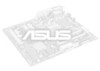
... storage through the sophisticated SD and MS devices. 1.3.2 Value-added solutions Overclocking The P4S333 overclocking features: • adjustable CPU frequency multiple in BIOS using the ASUS JumperFree™ solution • adjustable FSB/MEM frequency ratio • Stepless Frequency ...speaker, you will hear the messages informing you to provide friendly voice messages and alerts during the Power-On SelfTests (POST). ASUS P4S333 motherboard user guide 1-3 ASUS POST Reporter™ P4S333 offers a new exciting feature called the ASUS POST Reporter™ to customize the...
... storage through the sophisticated SD and MS devices. 1.3.2 Value-added solutions Overclocking The P4S333 overclocking features: • adjustable CPU frequency multiple in BIOS using the ASUS JumperFree™ solution • adjustable FSB/MEM frequency ratio • Stepless Frequency ...speaker, you will hear the messages informing you to provide friendly voice messages and alerts during the Power-On SelfTests (POST). ASUS P4S333 motherboard user guide 1-3 ASUS POST Reporter™ P4S333 offers a new exciting feature called the ASUS POST Reporter™ to customize the...
P4S333 English Manual
Page 16
... LAN PHY (optional) 17. Microphone jack (optional) 25. USB ports 29. PS/2 Keyboard port See page 1-6 for more information on page 1-5. 1. ATX power connector 5. ASUS ASIC 12. ACR slot 16. Audio controller (optional) 18. Game/MIDI port (optional) 24. DDR DIMM sockets 6. PCI ...you avoid mistakes that may damage the board and its physical configuration and available features to Chapter 2 for a brief description of the P4S333 motherboard as pointed out in the picture on the motherboard jumpers and connectors. 1-4 Chapter 1: Product introduction AGP slot 20. Line In...
... LAN PHY (optional) 17. Microphone jack (optional) 25. USB ports 29. PS/2 Keyboard port See page 1-6 for more information on page 1-5. 1. ATX power connector 5. ASUS ASIC 12. ACR slot 16. Audio controller (optional) 18. Game/MIDI port (optional) 24. DDR DIMM sockets 6. PCI ...you avoid mistakes that may damage the board and its physical configuration and available features to Chapter 2 for a brief description of the P4S333 motherboard as pointed out in the picture on the motherboard jumpers and connectors. 1-4 Chapter 1: Product introduction AGP slot 20. Line In...

P4S333 English Manual
Page 21
Chapter 2 This chapter describes the hardware setup procedures that you have to perform when installing system components. It includes details on the switches, jumpers, and connectors on the motherboard. Hardware information
Chapter 2 This chapter describes the hardware setup procedures that you have to perform when installing system components. It includes details on the switches, jumpers, and connectors on the motherboard. Hardware information

P4S333 English Manual
Page 24
... 45 PCI1 PCI2 SiS961 MuTLOL Media I/O JEN1 PWRTMP1 SIRQ1 PCI3 P4S333 PCI4 LED1 ® PCI5 PCI6 USB2 ACR1 CLRCMOS1 SMART CR2032 3V Lithium Cell CMOS Power Super I/O SMB1 SMARTCON1 IR1 CHASSIS1 ASUS ASIC with Hardware Monitor 2Mbit Firmware Hub CHASFAN1 USBV2 USBV3 USB1 ...IPANEL1 IDELED1 PANEL1 The audio and LAN features are grayed out in the above motherboard layout. MS1 DSW1 SD1 2-2 Chapter 2: Hardware information These components are optional.
... 45 PCI1 PCI2 SiS961 MuTLOL Media I/O JEN1 PWRTMP1 SIRQ1 PCI3 P4S333 PCI4 LED1 ® PCI5 PCI6 USB2 ACR1 CLRCMOS1 SMART CR2032 3V Lithium Cell CMOS Power Super I/O SMB1 SMARTCON1 IR1 CHASSIS1 ASUS ASIC with Hardware Monitor 2Mbit Firmware Hub CHASFAN1 USBV2 USBV3 USB1 ...IPANEL1 IDELED1 PANEL1 The audio and LAN features are grayed out in the above motherboard layout. MS1 DSW1 SD1 2-2 Chapter 2: Hardware information These components are optional.

P4S333 English Manual
Page 26
... execution of integer instructions, and a data transfer rate of the CPU into the socket may bend the pins and severely damage the CPU! 2-4 Chapter 2: Hardware information Gold Mark Note in the 478-pin package uses the Flip-Chip Pin Grid Array 2 (FC-PGA2) package technology, and includes the Intel® NetBurst...
... execution of integer instructions, and a data transfer rate of the CPU into the socket may bend the pins and severely damage the CPU! 2-4 Chapter 2: Hardware information Gold Mark Note in the 478-pin package uses the Flip-Chip Pin Grid Array 2 (FC-PGA2) package technology, and includes the Intel® NetBurst...

P4S333 English Manual
Page 28
The CPU fits only in place. Gold Mark 5. 3. DO NOT force the CPU into the socket until it firmly on the side tab to indicate that its marked corner matches the base of the socket lever. 4. When the CPU is locked. 2-6 Chapter 2: Hardware information The lever clicks on the socket while you push down the socket lever to prevent bending the pins and damaging the CPU! Position the CPU above the socket such that it is in place, press it fits in one correct orientation. Carefully insert the CPU into the socket to secure the CPU.
The CPU fits only in place. Gold Mark 5. 3. DO NOT force the CPU into the socket until it firmly on the side tab to indicate that its marked corner matches the base of the socket lever. 4. When the CPU is locked. 2-6 Chapter 2: Hardware information The lever clicks on the socket while you push down the socket lever to prevent bending the pins and damaging the CPU! Position the CPU above the socket such that it is in place, press it fits in one correct orientation. Carefully insert the CPU into the socket to secure the CPU.

P4S333 English Manual
Page 30
Position the fan with the retention mechanism on each corner of the module base. Retention Lock Retention Hole Retention Hook Snapped to the Retention Hole Keep the retention locks lifted upward while fitting the retention mechanism to the holes on top of the retention mechanism to the module base. 2-8 Chapter 2: Hardware information 2. Align and snap the four hooks of the heatsink. Make sure that the fan and retention mechanism assembly perfectly fits the heatsink and module base, otherwise you cannot snap the hooks into the holes.
Position the fan with the retention mechanism on each corner of the module base. Retention Lock Retention Hole Retention Hook Snapped to the Retention Hole Keep the retention locks lifted upward while fitting the retention mechanism to the holes on top of the retention mechanism to the module base. 2-8 Chapter 2: Hardware information 2. Align and snap the four hooks of the heatsink. Make sure that the fan and retention mechanism assembly perfectly fits the heatsink and module base, otherwise you cannot snap the hooks into the holes.

P4S333 English Manual
Page 32
... SDR DIMM is not backward compatible with SDR, and should be installed only in a socket specially designed for DDR DIMMs. 2-10 Chapter 2: Hardware information 2.5 System memory 2.5.1 Overview The motherboard comes with a notch so that it has a 184-pin footprint compared to perform two data operations in only.... DO NOT force a DIMM into a socket to 3GB system memory using 184-pin unbuffered non-ECC PC2700/2100/1600 DIMMs. 104 Pins P4S333 ® P4S333 184-Pin DDR DIMM Sockets 80 Pins A DDR DIMM is keyed with three Double Data Rate (DDR) Dual Inline Memory Module (DIMM) sockets...
... SDR DIMM is not backward compatible with SDR, and should be installed only in a socket specially designed for DDR DIMMs. 2-10 Chapter 2: Hardware information 2.5 System memory 2.5.1 Overview The motherboard comes with a notch so that it has a 184-pin footprint compared to perform two data operations in only.... DO NOT force a DIMM into a socket to 3GB system memory using 184-pin unbuffered non-ECC PC2700/2100/1600 DIMMs. 104 Pins P4S333 ® P4S333 184-Pin DDR DIMM Sockets 80 Pins A DDR DIMM is keyed with three Double Data Rate (DDR) Dual Inline Memory Module (DIMM) sockets...

P4S333 English Manual
Page 34
... the DIMM into the socket until the retaining clips snap back in place and the DIMM is properly seated. 2-12 Locked Retaining Clip Chapter 2: Hardware information Unlocked Retaining Clip 3. Follow these steps to unplug the power supply before adding or removing DIMMs or other system components. Align a DIMM on the socket...
... the DIMM into the socket until the retaining clips snap back in place and the DIMM is properly seated. 2-12 Locked Retaining Clip Chapter 2: Hardware information Unlocked Retaining Clip 3. Follow these steps to unplug the power supply before adding or removing DIMMs or other system components. Align a DIMM on the socket...

P4S333 English Manual
Page 35
...4. 2.6 Expansion slots In the future, you removed earlier. 6. Secure the card to the chassis with it and make the necessary hardware settings for information on the next page. 3. Install the software drivers for later use . Keep the screw for the expansion card. Turn on the slot. 5. ... card, read the documentation that they support. Assign an IRQ to the tables on BIOS setup. 2. Make sure to install expansion cards. ASUS P4S333 motherboard user guide 2-13 See Chapter 4 for the card. 2. Remove the system unit cover (if your motherboard is completely seated on the...
...4. 2.6 Expansion slots In the future, you removed earlier. 6. Secure the card to the chassis with it and make the necessary hardware settings for information on the next page. 3. Install the software drivers for later use . Keep the screw for the expansion card. Turn on the slot. 5. ... card, read the documentation that they support. Assign an IRQ to the tables on BIOS setup. 2. Make sure to install expansion cards. ASUS P4S333 motherboard user guide 2-13 See Chapter 4 for the card. 2. Remove the system unit cover (if your motherboard is completely seated on the...
P4S333 English Manual
Page 36
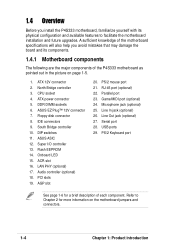
... need IRQ assignments. B - shared - - shared - Otherwise, conflicts will arise between the two PCI groups, making the system unstable and the card inoperable. 2-14 Chapter 2: Hardware information shared D - - - shared - - - - shared - - - - C - - shared shared - - - shared - - - - Standard Interrupt Assignments IRQ Priority Standard Function 0 1 System Timer 1 2 Keyboard Controller 2 N/A Programmable Interrupt 3* 11 Communications Port (COM2) 4* 12 Communications...
... need IRQ assignments. B - shared - - shared - Otherwise, conflicts will arise between the two PCI groups, making the system unstable and the card inoperable. 2-14 Chapter 2: Hardware information shared D - - - shared - - - - shared - - - - C - - shared shared - - - shared - - - - Standard Interrupt Assignments IRQ Priority Standard Function 0 1 System Timer 1 2 Keyboard Controller 2 N/A Programmable Interrupt 3* 11 Communications Port (COM2) 4* 12 Communications...

P4S333 English Manual
Page 38
P4S333 ® P4S333 Advanced Communication Riser (ACR) 2-16 Chapter 2: Hardware information The slot also accommodates the Home Phoneline Networking Alliance (HPNA) or Home Networking cards. The ACR slot shares with Audio Modem Riser (AMR) cards. If you installed a card into the PCI6 slot, you may not use the ACR slot. 2.6.5 ACR slot The Advanced Communication Riser (ACR) slot supports interface cards that integrates audio, modem, and network functionalities. The ACR slot is backward compatible with the PCI slot 6.
P4S333 ® P4S333 Advanced Communication Riser (ACR) 2-16 Chapter 2: Hardware information The slot also accommodates the Home Phoneline Networking Alliance (HPNA) or Home Networking cards. The ACR slot shares with Audio Modem Riser (AMR) cards. If you installed a card into the PCI6 slot, you may not use the ACR slot. 2.6.5 ACR slot The Advanced Communication Riser (ACR) slot supports interface cards that integrates audio, modem, and network functionalities. The ACR slot is backward compatible with the PCI slot 6.

P4S333 English Manual
Page 40
...). Frequencies other than the recommended CPU bus frequencies are not guaranteed to the recommended settings. KBPWR1 P4S333 ® 2 1 +5V 3 2 +5VSB (Default) P4S333 Keyboard Power Setting 2-18 Chapter 2: Hardware information Keyboard power (3-pin KBPWR1) This jumper allows you press a key on the +5VSB lead, ... ON 12345 CPU 100MHz 100MHz 100MHz 100MHz 100MHz DRAM 100MHz 133MHz 150MHz 160MHz 166MHz P4S333 ® CPU 105MHz 108MHz 112MHz 133MHz 133MHz DRAM 140MHz 144MHz 149MHz 133MHz 166MHz P4S333 CPU External Frequency Selection Set the CPU frequency only to be stable. 3. CPU...
...). Frequencies other than the recommended CPU bus frequencies are not guaranteed to the recommended settings. KBPWR1 P4S333 ® 2 1 +5V 3 2 +5VSB (Default) P4S333 Keyboard Power Setting 2-18 Chapter 2: Hardware information Keyboard power (3-pin KBPWR1) This jumper allows you press a key on the +5VSB lead, ... ON 12345 CPU 100MHz 100MHz 100MHz 100MHz 100MHz DRAM 100MHz 133MHz 150MHz 160MHz 166MHz P4S333 ® CPU 105MHz 108MHz 112MHz 133MHz 133MHz DRAM 140MHz 144MHz 149MHz 133MHz 166MHz P4S333 CPU External Frequency Selection Set the CPU frequency only to be stable. 3. CPU...
