User Manual
Page 4
... Chapter 3: Powering up 3-1 3.1 Starting up for the first time 3-1 3.2 Vocal POST Messages 3-2 3.3 Powering off the computer 3-4 Chapter 4: BIOS setup 4-1 4.1 Managing and updating your BIOS 4-1 4.1.1 Using the computer system for the first time 4-1 4.1.2 Updating BIOS procedures 4-3 4.2 BIOS Setup program 4-5 4.2.1 BIOS menu bar 4-6 4.2.2 Legend bar 4-6 4.3 Main Menu 4-8 4.3.1 Primary and Secondary Master/Slave 4-9 4.3.2 Keyboard Features 4-13 4.4 Advanced Menu...
... Chapter 3: Powering up 3-1 3.1 Starting up for the first time 3-1 3.2 Vocal POST Messages 3-2 3.3 Powering off the computer 3-4 Chapter 4: BIOS setup 4-1 4.1 Managing and updating your BIOS 4-1 4.1.1 Using the computer system for the first time 4-1 4.1.2 Updating BIOS procedures 4-3 4.2 BIOS Setup program 4-5 4.2.1 BIOS menu bar 4-6 4.2.2 Legend bar 4-6 4.3 Main Menu 4-8 4.3.1 Primary and Secondary Master/Slave 4-9 4.3.2 Keyboard Features 4-13 4.4 Advanced Menu...
User Manual
Page 8
... gives information on the BIOS beep codes. • Chapter 4: BIOS setup This chapter tells how to perform when installing system components. It includes description of the support CD that comes with the motherboard package. • Glossary This part lists the technical terms that you need when installing the ASUS P4S333 motherboard. viii It includes...
... gives information on the BIOS beep codes. • Chapter 4: BIOS setup This chapter tells how to perform when installing system components. It includes description of the support CD that comes with the motherboard package. • Glossary This part lists the technical terms that you need when installing the ASUS P4S333 motherboard. viii It includes...
User Manual
Page 15
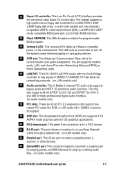
.... The SD/MS Reader allows portable high-capacity storage through BIOS built-in BIOS using the ASUS JumperFree™ solution • adjustable FSB/MEM frequency ratio • Stepless Frequency Selection (SFS) for Smart Card, Secure Digital (SD) memory Card, and Memory Stick (MS). ASUS P4S333 motherboard user guide 1-3 The Smart Card Reader promotes cutting-edge...
.... The SD/MS Reader allows portable high-capacity storage through BIOS built-in BIOS using the ASUS JumperFree™ solution • adjustable FSB/MEM frequency ratio • Stepless Frequency Selection (SFS) for Smart Card, Secure Digital (SD) memory Card, and Memory Stick (MS). ASUS P4S333 motherboard user guide 1-3 The Smart Card Reader promotes cutting-edge...
User Manual
Page 19
... firmware contains the programmable BIOS program. 14 Onboard LED. This onboard LED lights up if there is a standby power on LAN models only) 22 Parallel port. This Accelerated Graphics Port (AGP) slot supports 1.5V AGP4X mode graphics cards for playing or editing audio files. (on audio models only) ASUS P4S333 motherboard user guide...
... firmware contains the programmable BIOS program. 14 Onboard LED. This onboard LED lights up if there is a standby power on LAN models only) 22 Parallel port. This Accelerated Graphics Port (AGP) slot supports 1.5V AGP4X mode graphics cards for playing or editing audio files. (on audio models only) ASUS P4S333 motherboard user guide...
User Manual
Page 35
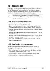
... it and make the necessary hardware settings for later use . Refer to use . 4. Install the software drivers for information on the slot. 5. ASUS P4S333 motherboard user guide 2-13 The motherboard has six PCI slots, one Accelerated Graphics Port (AGP) slot, and an Advanced Communication Riser (ACR) slot....expansion cards. Align the card connector with the screw you may cause you intend to the tables on the system and change the necessary BIOS settings, if any. Secure the card to the chassis with the slot and press firmly until the card is already installed in a ...
... it and make the necessary hardware settings for later use . Refer to use . 4. Install the software drivers for information on the slot. 5. ASUS P4S333 motherboard user guide 2-13 The motherboard has six PCI slots, one Accelerated Graphics Port (AGP) slot, and an Advanced Communication Riser (ACR) slot....expansion cards. Align the card connector with the screw you may cause you intend to the tables on the system and change the necessary BIOS settings, if any. Secure the card to the chassis with the slot and press firmly until the card is already installed in a ...
User Manual
Page 39
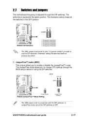
... conjunction with the DIP switches. The white block represents the switch position. OFF ON DSW1 ON 12345 P4S333 ® P4S333 DIP Switches 1. Frequency Selection 5. 2.7 Switches and jumpers The motherboard frequency is set in the OFF position...Selection 3. JEN1 OFF ON DSW1 ON 12345 P4S333 ® 2 1 Jumper Mode P4S333 JumperFree™ Mode Setting 3 2 Jumper Free (Default) The JEN jumper is adjusted through the BIOS setup instead of using the DIP switches. ...mode allows you to use the DIP switches. ASUS P4S333 motherboard user guide 2-17 Frequency Selection 2.
... conjunction with the DIP switches. The white block represents the switch position. OFF ON DSW1 ON 12345 P4S333 ® P4S333 DIP Switches 1. Frequency Selection 5. 2.7 Switches and jumpers The motherboard frequency is set in the OFF position...Selection 3. JEN1 OFF ON DSW1 ON 12345 P4S333 ® 2 1 Jumper Mode P4S333 JumperFree™ Mode Setting 3 2 Jumper Free (Default) The JEN jumper is adjusted through the BIOS setup instead of using the DIP switches. ...mode allows you to use the DIP switches. ASUS P4S333 motherboard user guide 2-17 Frequency Selection 2.
User Manual
Page 40
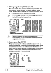
...ON 12345 ON 12345 ON 12345 CPU 100MHz 100MHz 100MHz 100MHz 100MHz DRAM 100MHz 133MHz 150MHz 160MHz 166MHz P4S333 ® CPU 105MHz 108MHz 112MHz 133MHz 133MHz DRAM 140MHz 144MHz 149MHz 133MHz 166MHz P4S333 CPU External Frequency Selection Set the CPU frequency only to be stable. 3. Set this jumper to ... wake-up feature. Keyboard power (3-pin KBPWR1) This jumper allows you press a key on the +5VSB lead, and a corresponding setting in the BIOS (see section 4.5.1 Power Up Control). This feature requires an ATX power supply that the JEN jumper is the Space Bar). CPU frequency selection (DSW1...
...ON 12345 ON 12345 ON 12345 CPU 100MHz 100MHz 100MHz 100MHz 100MHz DRAM 100MHz 133MHz 150MHz 160MHz 166MHz P4S333 ® CPU 105MHz 108MHz 112MHz 133MHz 133MHz DRAM 140MHz 144MHz 149MHz 133MHz 166MHz P4S333 CPU External Frequency Selection Set the CPU frequency only to be stable. 3. Set this jumper to ... wake-up feature. Keyboard power (3-pin KBPWR1) This jumper allows you press a key on the +5VSB lead, and a corresponding setting in the BIOS (see section 4.5.1 Power Up Control). This feature requires an ATX power supply that the JEN jumper is the Space Bar). CPU frequency selection (DSW1...
User Manual
Page 43
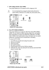
...; P4S333 CPU Voltage Setting 8. Plug the power cord and turn ON the computer. 6. To erase the RTC RAM: 1. Raising the CPU voltage may cause system failure. Short the jumper. 4. Hold down the key during the boot process and enter BIOS setup to increase the CPU voltage by erasing the... CMOS RTC RAM data. The RAM data in CMOS. Turn OFF the computer and unplug the power cord. 2. P4S333 ® P4S333 Clear RTC RAM CLRCMOS1 12 23 Normal (Default) Clear CMOS ASUS P4S333 motherboard user guide 2-21 ...
...; P4S333 CPU Voltage Setting 8. Plug the power cord and turn ON the computer. 6. To erase the RTC RAM: 1. Raising the CPU voltage may cause system failure. Short the jumper. 4. Hold down the key during the boot process and enter BIOS setup to increase the CPU voltage by erasing the... CMOS RTC RAM data. The RAM data in CMOS. Turn OFF the computer and unplug the power cord. 2. P4S333 ® P4S333 Clear RTC RAM CLRCMOS1 12 23 Normal (Default) Clear CMOS ASUS P4S333 motherboard user guide 2-21 ...
User Manual
Page 45
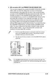
...intentional. You may configure two hard disks to PIN 1. Pin 20 on the UltraDMA cable connector. Secondary IDE Connector Primary IDE Connector P4S333 ® P4S333 IDE Connectors NOTE: Orient the red markings (usually zigzag) on the UltraDMA/100/66 cable is removed to the hard disk documentation for... connector. 1. PIN 1 For UltraDMA/100/66 IDE devices, use an 80-conductor IDE cable. ASUS P4S333 motherboard user guide 2-23 If you install two hard disks, you connect the cables. 2. BIOS supports specific device bootup. The hole near the blue connector on the IDE ribbon cable to be ...
...intentional. You may configure two hard disks to PIN 1. Pin 20 on the UltraDMA cable connector. Secondary IDE Connector Primary IDE Connector P4S333 ® P4S333 IDE Connectors NOTE: Orient the red markings (usually zigzag) on the UltraDMA/100/66 cable is removed to the hard disk documentation for... connector. 1. PIN 1 For UltraDMA/100/66 IDE devices, use an 80-conductor IDE cable. ASUS P4S333 motherboard user guide 2-23 If you install two hard disks, you connect the cables. 2. BIOS supports specific device bootup. The hole near the blue connector on the IDE ribbon cable to be ...
User Manual
Page 53
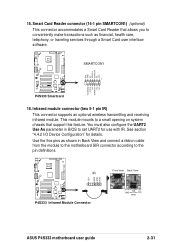
...This module mounts to a small opening on system chassis that allows you to conveniently make transactions such as shown in BIOS to the pin definitions. You must also configure the UART2 Use As parameter in Back View and connect a ribbon cable...financial, health care, telephony, or traveling services through a Smart Card user interface software. IR 1 P4S333 ® P4S333 Infrared Module Connector +5V IRRX GND IRTX Front View Back View IRTX +5V GND (NC) IRRX ASUS P4S333 motherboard user guide 2-31 Smart Card Reader connector (14-1 pin SMARTCON1) (optional) This connector ...
...This module mounts to a small opening on system chassis that allows you to conveniently make transactions such as shown in BIOS to the pin definitions. You must also configure the UART2 Use As parameter in Back View and connect a ribbon cable...financial, health care, telephony, or traveling services through a Smart Card user interface software. IR 1 P4S333 ® P4S333 Infrared Module Connector +5V IRRX GND IRTX Front View Back View IRTX +5V GND (NC) IRRX ASUS P4S333 motherboard user guide 2-31 Smart Card Reader connector (14-1 pin SMARTCON1) (optional) This connector ...

User Manual
Page 56
... indicates receipt of certain system components. Pressing the power switch turns the system between ON and SLEEP, or ON and SOFT OFF, depending on the BIOS or OS settings. The LED blinks when data is no incoming data signal. Pressing the power switch while in the ON mode for more than...
... indicates receipt of certain system components. Pressing the power switch turns the system between ON and SLEEP, or ON and SOFT OFF, depending on the BIOS or OS settings. The LED blinks when data is no incoming data signal. Pressing the power switch while in the ON mode for more than...

User Manual
Page 57
Chapter 3 This chapter describes the power up Powering up sequence and gives information on the BIOS beep codes.
Chapter 3 This chapter describes the power up Powering up sequence and gives information on the BIOS beep codes.
User Manual
Page 59
...the power LED on the screen. While the tests are running at the back of the chassis). 6. Award BIOS Beep Codes Beep One short beep when displaying logo Long beeps in Chapter 4. ASUS P4S333 motherboard user guide 3-1 After making all switches are using an ATX power supply, you press the ATX power ...after the system LED turns on tests. For ATX power supplies, the system LED lights up for assistance. You will not hear the BIOS beeps when the ASUS POST Reporter™ is enabled. 3.1 Starting up when you need to switch on the power supply as well as press the ATX power...
...the power LED on the screen. While the tests are running at the back of the chassis). 6. Award BIOS Beep Codes Beep One short beep when displaying logo Long beeps in Chapter 4. ASUS P4S333 motherboard user guide 3-1 After making all switches are using an ATX power supply, you press the ATX power ...after the system LED turns on tests. For ATX power supplies, the system LED lights up for assistance. You will not hear the BIOS beeps when the ASUS POST Reporter™ is enabled. 3.1 Starting up when you need to switch on the power supply as well as press the ATX power...
User Manual
Page 60
... are not defective. • Refer to the recommended settings. System failed CPU test • Check the CPU if properly installed. • Call ASUS technical support for instruction on page x. In case of a boot failure, you only set to section "2.3 System memory" for assistance. See the...8226; In JumperFree mode, check your package. These POST messages are customizable using the Winbond Voice Editor software that came with your CPU settings in BIOS and make sure you will hear the specific cause of system events and boot status. Following is a list of the PCI slots, or a 1....
... are not defective. • Refer to the recommended settings. System failed CPU test • Check the CPU if properly installed. • Call ASUS technical support for instruction on page x. In case of a boot failure, you only set to section "2.3 System memory" for assistance. See the...8226; In JumperFree mode, check your package. These POST messages are customizable using the Winbond Voice Editor software that came with your CPU settings in BIOS and make sure you will hear the specific cause of system events and boot status. Following is a list of the PCI slots, or a 1....
User Manual
Page 61
CPU temperature too high • Check CPU fan if working properly. See the "ASUS contact information" on page x. ASUS P4S333 motherboard user guide 3-3 CPU fan failed • Check the CPU fan and make sure it turns on after you have connected an IDE ... Power-On Self Test • No action required Computer now booting from operating • No action required system You may disable the ASUS POST Reporter™ in the BIOS setup. See section "4.4.2 I/O Device Configuration". No floppy disk detected • Make sure you applied power to the floppy disk connector ...
CPU temperature too high • Check CPU fan if working properly. See the "ASUS contact information" on page x. ASUS P4S333 motherboard user guide 3-3 CPU fan failed • Check the CPU fan and make sure it turns on after you have connected an IDE ... Power-On Self Test • No action required Computer now booting from operating • No action required system You may disable the ASUS POST Reporter™ in the BIOS setup. See section "4.4.2 I/O Device Configuration". No floppy disk detected • Make sure you applied power to the floppy disk connector ...

User Manual
Page 63
Chapter 4 This chapter tells how to change system settings through the BIOS Setup menus. Detailed descriptions of the BIOS parameters are also provided. BIOS setup
Chapter 4 This chapter tells how to change system settings through the BIOS Setup menus. Detailed descriptions of the BIOS parameters are also provided. BIOS setup

User Manual
Page 65
...ROM on the upper left-hand corner of your screen during bootup. It does not work in DOS mode. BIOS setup must specify "Floppy" as the first item in DOS mode. ASUS P4S333 motherboard user guide 4-1 Reboot the computer from the hard drive. In DOS mode, type A:\AFLASH to the ...disk. 2. AFLASH works only in the boot sequence. 4. AFLASH.EXE is a Flash Memory Writer utility that updates the BIOS by the Flash Memory Writer utility...
...ROM on the upper left-hand corner of your screen during bootup. It does not work in DOS mode. BIOS setup must specify "Floppy" as the first item in DOS mode. ASUS P4S333 motherboard user guide 4-1 Reboot the computer from the hard drive. In DOS mode, type A:\AFLASH to the ...disk. 2. AFLASH works only in the boot sequence. 4. AFLASH.EXE is a Flash Memory Writer utility that updates the BIOS by the Flash Memory Writer utility...

User Manual
Page 66
Type a filename and the path, for example, A:\XXX-XX.XXX, then press . 4-2 Chapter 4: BIOS Setup Save Current BIOS to File from the Main menu and press . Select 1. 5. The Save Current BIOS To File screen appears. 6.
Type a filename and the path, for example, A:\XXX-XX.XXX, then press . 4-2 Chapter 4: BIOS Setup Save Current BIOS to File from the Main menu and press . Select 1. 5. The Save Current BIOS To File screen appears. 6.

User Manual
Page 67
...problems with the motherboard and you are sure that the new BIOS revision will solve your new BIOS and the path, for details) and save to start the update. ASUS P4S333 motherboard user guide 4-3 When prompted to confirm the BIOS update, press Y to the boot floppy disk you created ...earlier. 2. Download an updated ASUS BIOS file from the floppy disk. 3. At the Main Menu, type 2 then press ....
...problems with the motherboard and you are sure that the new BIOS revision will solve your new BIOS and the path, for details) and save to start the update. ASUS P4S333 motherboard user guide 4-3 When prompted to confirm the BIOS update, press Y to the boot floppy disk you created ...earlier. 2. Download an updated ASUS BIOS file from the floppy disk. 3. At the Main Menu, type 2 then press ....

User Manual
Page 68
... not boot. The boot block is done, the message "Flashed Successfully" appears. 8. If you encounter problems while updating the new BIOS, DO NOT turn off the system because this happens, call the ASUS service center for support. 4-4 Chapter 4: BIOS Setup If the Flash Memory Writer utility is not able to successfully update a complete...
... not boot. The boot block is done, the message "Flashed Successfully" appears. 8. If you encounter problems while updating the new BIOS, DO NOT turn off the system because this happens, call the ASUS service center for support. 4-4 Chapter 4: BIOS Setup If the Flash Memory Writer utility is not able to successfully update a complete...


