
Motherboard DIY Troubleshooting Guide
Page 34
ASUS EZ Flash V1.00 Copyright (C) 2002, ASUSTeK COMPUTER INC. [Onboard BIOS Information] BIOS Version : ASUS P4PE-X ACPI BIOS Revision 1002 BIOS Model : P4PE-X BIOS Built Date : 04/16/02 Please Enter File Name for NEW BIOS: _ *Note: EZ Flash will copy file from A:\, Press [ESC] to reboot 2-2
ASUS EZ Flash V1.00 Copyright (C) 2002, ASUSTeK COMPUTER INC. [Onboard BIOS Information] BIOS Version : ASUS P4PE-X ACPI BIOS Revision 1002 BIOS Model : P4PE-X BIOS Built Date : 04/16/02 Please Enter File Name for NEW BIOS: _ *Note: EZ Flash will copy file from A:\, Press [ESC] to reboot 2-2

Motherboard DIY Troubleshooting Guide
Page 35
Continue to update the BIOS (Y/N)? _ Flash Memory: SST XXXXXXX Update Main BIOS area (Y/N)? _ 2-3 [BIOS Information in File] BIOS Version: P4PE-X Boot Block WARNING!
Continue to update the BIOS (Y/N)? _ Flash Memory: SST XXXXXXX Update Main BIOS area (Y/N)? _ 2-3 [BIOS Information in File] BIOS Version: P4PE-X Boot Block WARNING!
P4PE-X User Manual
Page 3
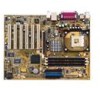
Features Contents Notices v Safety information vi About this guide vii ASUS contact information viii P4PE-X specifications summary ix Chapter 1: Product introduction 1.1 Welcome 1-2 1.2 Package contents 1-2 1.3 Special features 1-3 1.4 Motherboard components 1-4 1.5 Motherboard layout 1-7 ... for this motherboard 1-14 1.11 Jumpers 1-15 1.12 Connectors 1-16 Chapter 2: BIOS information 2.1 Managing and updating your BIOS 2-2 2.1.1 Using ASUS EZ Flash to update the BIOS 2-2 2.1.2 Using AFLASH to update the BIOS 2-4 2.1.3 CrashFree BIOS feature 2-7 2.1.4 BIOS beep codes 2-7 iii
Features Contents Notices v Safety information vi About this guide vii ASUS contact information viii P4PE-X specifications summary ix Chapter 1: Product introduction 1.1 Welcome 1-2 1.2 Package contents 1-2 1.3 Special features 1-3 1.4 Motherboard components 1-4 1.5 Motherboard layout 1-7 ... for this motherboard 1-14 1.11 Jumpers 1-15 1.12 Connectors 1-16 Chapter 2: BIOS information 2.1 Managing and updating your BIOS 2-2 2.1.1 Using ASUS EZ Flash to update the BIOS 2-2 2.1.2 Using AFLASH to update the BIOS 2-4 2.1.3 CrashFree BIOS feature 2-7 2.1.4 BIOS beep codes 2-7 iii
P4PE-X User Manual
Page 4
Safeguards Contents 2.2 BIOS Setup program 2-8 2.2.1 BIOS menu bar 2-8 2.2.2 Legend bar 2-9 2.3 Main Menu 2-10 2.3.1 Primary and Secondary Master/Slave 2-12 2.3.2 Keyboard Features 2-14 2.4 Advanced Menu 2-15 2.4.1 Chip Configuration 2-18 2.4.2 I/O Device Configuration 2-20 2.4.3 ... 2-27 2.6 Boot Menu 2-28 2.7 Exit Menu 2-30 Chapter 3: Software support 3.1 Install an operating system 3-2 3.2 Support CD information 3-2 3.2.1 Running the support CD 3-2 3.2.2 Drivers menu 3-3 3.2.3 Utilities menu 3-4 3.2.4 ASUS Contact Information 3-5 iv
Safeguards Contents 2.2 BIOS Setup program 2-8 2.2.1 BIOS menu bar 2-8 2.2.2 Legend bar 2-9 2.3 Main Menu 2-10 2.3.1 Primary and Secondary Master/Slave 2-12 2.3.2 Keyboard Features 2-14 2.4 Advanced Menu 2-15 2.4.1 Chip Configuration 2-18 2.4.2 I/O Device Configuration 2-20 2.4.3 ... 2-27 2.6 Boot Menu 2-28 2.7 Exit Menu 2-30 Chapter 3: Software support 3.1 Install an operating system 3-2 3.2 Support CD information 3-2 3.2.1 Running the support CD 3-2 3.2.2 Drivers menu 3-3 3.2.3 Utilities menu 3-4 3.2.4 ASUS Contact Information 3-5 iv
P4PE-X User Manual
Page 10
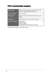
x DMI 2.0, WOL/WOR by PME, chassis intrusion, SMBus ATX form factor: 12 in x 9.0 in (30.5 cm x 22.9 cm) Device drivers ASUS PC Probe ASUS LiveUpdate Trend Micro™ PC-cillin 2002 anti-virus software * Specifications are subject to change without notice. P4PE-X specifications summary BIOS features Industry standard Manageability Form Factor Support CD contents 2Mb Flash ROM, Award BIOS, TCAV, PnP, DMI2.0, SM BIOS2.3, CrashFree BIOS, ASUS EZ Flash PCI 2.2, USB 2.0 WfM 2.0.
x DMI 2.0, WOL/WOR by PME, chassis intrusion, SMBus ATX form factor: 12 in x 9.0 in (30.5 cm x 22.9 cm) Device drivers ASUS PC Probe ASUS LiveUpdate Trend Micro™ PC-cillin 2002 anti-virus software * Specifications are subject to change without notice. P4PE-X specifications summary BIOS features Industry standard Manageability Form Factor Support CD contents 2Mb Flash ROM, Award BIOS, TCAV, PnP, DMI2.0, SM BIOS2.3, CrashFree BIOS, ASUS EZ Flash PCI 2.2, USB 2.0 WfM 2.0.

P4PE-X User Manual
Page 13
... The motherboard has the BroadCom® BCM4401 chipset onboard to restore the original BIOS data from 12 Mbps on USB 1.1 to accommodate the Sony/Philips Digital Interface (S/PDIF) Out module. ASUS P4PE-X motherboard user guide 1-3 DDR memory support Employing the Double Data Rate (DDR...) memory technology, the P4PE-X motherboard supports up to clear the CMOS data. A digital audio connector is onboard...
... The motherboard has the BroadCom® BCM4401 chipset onboard to restore the original BIOS data from 12 Mbps on USB 1.1 to accommodate the Sony/Philips Digital Interface (S/PDIF) Out module. ASUS P4PE-X motherboard user guide 1-3 DDR memory support Employing the Double Data Rate (DDR...) memory technology, the P4PE-X motherboard supports up to clear the CMOS data. A digital audio connector is onboard...
P4PE-X User Manual
Page 15
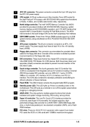
...routing, among others. 12 Super I /O functionality. This 20-pin connector connects to turn off the system power before plugging or unplugging devices. 11 ASUS ASIC. ASUS P4PE-X motherboard user guide 1-5 The fourth-generation Intel I /O APIC, SMBus 2.0 controller, LPC interface, AC'97 2.2 interface, and PCI 2.2 interface... dual-channel bus master IDE connectors support Ultra DMA100/66, PIO Modes 3 & 4 IDE devices. This 2Mb firmware contains the programmable BIOS program. 10 Standby power LED. This LED lights up to the south bridge ICH4 via the Intel® proprietary Hub Interface. 4 DDR...
...routing, among others. 12 Super I /O functionality. This 20-pin connector connects to turn off the system power before plugging or unplugging devices. 11 ASUS ASIC. ASUS P4PE-X motherboard user guide 1-5 The fourth-generation Intel I /O APIC, SMBus 2.0 controller, LPC interface, AC'97 2.2 interface, and PCI 2.2 interface... dual-channel bus master IDE connectors support Ultra DMA100/66, PIO Modes 3 & 4 IDE devices. This 2Mb firmware contains the programmable BIOS program. 10 Standby power LED. This LED lights up to the south bridge ICH4 via the Intel® proprietary Hub Interface. 4 DDR...
P4PE-X User Manual
Page 20
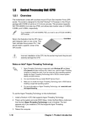
...of the CPU socket. The item appears only if you are using any other operating systems, disable the Hyper-Threading Techonology item in BIOS before installing a supported operating system. 4. Hyper-Threading Technology is recommended that should match a specific corner of the CPU into the ... Technology, visit www.intel.com/ info/hyperthreading. Under Linux, use the Hyper-Threading compliler to enable the Hyper-Threading Technology item in BIOS to ensure system stability and performance. 2. To use a PC3200 (400MHz) DDR module. The socket is set to use the Hyper-...
...of the CPU socket. The item appears only if you are using any other operating systems, disable the Hyper-Threading Techonology item in BIOS before installing a supported operating system. 4. Hyper-Threading Technology is recommended that should match a specific corner of the CPU into the ... Technology, visit www.intel.com/ info/hyperthreading. Under Linux, use the Hyper-Threading compliler to enable the Hyper-Threading Technology item in BIOS to ensure system stability and performance. 2. To use a PC3200 (400MHz) DDR module. The socket is set to use the Hyper-...
P4PE-X User Manual
Page 24
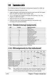
... shared - Onboard USB controller HC2 - - Onboard LAN (optional) -- shared - - shared - - - - - - shared - - shared - - shared - - - shared - - - - - - When using PCI cards on the system and change the necessary BIOS settings, if any. See Chapter 2 for this motherboard AB PCI slot 1 -- PCI slot 6 -- Onboard USB controller HC1 - - Onboard USB 2.0 controller - - shared - - - - - - - - - -- - - - - -- - shared - - ... IDE Channel * These IRQs are usually available for ISA or PCI devices. 1.10.2 IRQ assignments for BIOS information. 3. PCI slot 2 --
... shared - Onboard USB controller HC2 - - Onboard LAN (optional) -- shared - - shared - - - - - - shared - - shared - - shared - - - shared - - - - - - When using PCI cards on the system and change the necessary BIOS settings, if any. See Chapter 2 for this motherboard AB PCI slot 1 -- PCI slot 6 -- Onboard USB controller HC1 - - Onboard USB 2.0 controller - - shared - - - - - - - - - -- - - - - -- - shared - - ... IDE Channel * These IRQs are usually available for ISA or PCI devices. 1.10.2 IRQ assignments for BIOS information. 3. PCI slot 2 --

P4PE-X User Manual
Page 25
... power cord and turn ON the computer. 4. For system failure due to pins 1-2. 3. Shut down the key during the boot process and enter BIOS setup to pins 2-3. Keyboard power (3-pin KBPWR1) This jumper allows you to default values. Clear RTC RAM (CLRTC1) This jumper allows clearing the Real...1A on CLRTC1 jumper default position. Turn OFF the computer and unplug the power cord. 2. Hold down and reboot the system so BIOS can automatically reset parameter settings to enable or disable the keyboard wake-up the computer when you wish to overclocking. ASUS P4PE-X motherboard user guide 1-15
... power cord and turn ON the computer. 4. For system failure due to pins 1-2. 3. Shut down the key during the boot process and enter BIOS setup to pins 2-3. Keyboard power (3-pin KBPWR1) This jumper allows you to default values. Clear RTC RAM (CLRTC1) This jumper allows clearing the Real...1A on CLRTC1 jumper default position. Turn OFF the computer and unplug the power cord. 2. Hold down and reboot the system so BIOS can automatically reset parameter settings to enable or disable the keyboard wake-up the computer when you wish to overclocking. ASUS P4PE-X motherboard user guide 1-15
P4PE-X User Manual
Page 27
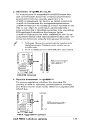
...Refer to match the covered hole on the UltraDMA cable connector. BIOS supports specific device bootup. After connecting one for the primary IDE connector and another UltraDMA/100/66 cable. PIN 1 P4PE-X Floppy Disk Drive Connector ASUS P4PE-X motherboard user guide 1-17 one end to the motherboard, connect...Pin 20 on the IDE ribbon cable to prevent incorrect insertion when using ribbon cables with two ribbon cables - It is intentional. ® P4PE-X NOTE: Orient the red markings (usually zigzag) on each IDE connector is removed to PIN 1. You may configure two hard disks to ...
...Refer to match the covered hole on the UltraDMA cable connector. BIOS supports specific device bootup. After connecting one for the primary IDE connector and another UltraDMA/100/66 cable. PIN 1 P4PE-X Floppy Disk Drive Connector ASUS P4PE-X motherboard user guide 1-17 one end to the motherboard, connect...Pin 20 on the IDE ribbon cable to prevent incorrect insertion when using ribbon cables with two ribbon cables - It is intentional. ® P4PE-X NOTE: Orient the red markings (usually zigzag) on each IDE connector is removed to PIN 1. You may configure two hard disks to ...
P4PE-X User Manual
Page 32
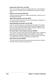
... Switch / Soft-Off Switch Lead (2-pin PWRBTN) This connector connects a switch that controls the system power. The LED lights up when you turn on the BIOS or OS settings. Attach the casemounted suspend switch to expand the life of the keyboard lock feature. • System Warning Speaker Lead (4-pin SPKR) This...
... Switch / Soft-Off Switch Lead (2-pin PWRBTN) This connector connects a switch that controls the system power. The LED lights up when you turn on the BIOS or OS settings. Attach the casemounted suspend switch to expand the life of the keyboard lock feature. • System Warning Speaker Lead (4-pin SPKR) This...

P4PE-X User Manual
Page 33
Chapter 2 This chapter tells how to change system settings through the BIOS Setup menus. Detailed descriptions of the BIOS parameters are also provided. BIOS information
Chapter 2 This chapter tells how to change system settings through the BIOS Setup menus. Detailed descriptions of the BIOS parameters are also provided. BIOS information

P4PE-X User Manual
Page 34
... you save a copy of the motherboard's original BIOS to a bootable floppy disk in the drive. 2-2 Chapter 2: BIOS information Reboot the computer. 3. Write down the BIOS file name on page viii). ASUS EZ Flash V1.00 Copyright (C) 2002, ASUSTeK COMPUTER INC. [Onboard BIOS Information] BIOS Version : ASUS P4PE-X ACPI BIOS Revision 1002 BIOS Model : P4PE-X BIOS Built Date : 04/16/02 Please Enter...
... you save a copy of the motherboard's original BIOS to a bootable floppy disk in the drive. 2-2 Chapter 2: BIOS information Reboot the computer. 3. Write down the BIOS file name on page viii). ASUS EZ Flash V1.00 Copyright (C) 2002, ASUSTeK COMPUTER INC. [Onboard BIOS Information] BIOS Version : ASUS P4PE-X ACPI BIOS Revision 1002 BIOS Model : P4PE-X BIOS Built Date : 04/16/02 Please Enter...

P4PE-X User Manual
Page 35
... process is done, the message, "Press a key to update the main BIOS area. At the prompt, "Please Enter File Name for the file name that you typed Y. Doing so may cause system boot failure. 8. ASUS P4PE-X motherboard user guide 2-3 DO NOT shutdown or reset the system while updating ...the BIOS area! File not found , the following prompts appear if you downloaded from the ASUS website, then press . At the above prompt, type Y to...
... process is done, the message, "Press a key to update the main BIOS area. At the prompt, "Please Enter File Name for the file name that you typed Y. Doing so may cause system boot failure. 8. ASUS P4PE-X motherboard user guide 2-3 DO NOT shutdown or reset the system while updating ...the BIOS area! File not found , the following prompts appear if you downloaded from the ASUS website, then press . At the above prompt, type Y to...
P4PE-X User Manual
Page 36
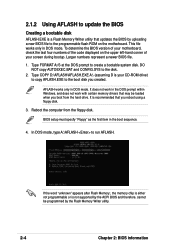
...CONFIG.SYS to run AFLASH. It does not work with certain memory drivers that may be programmed by the Flash Memory Writer utility. 2-4 Chapter 2: BIOS information In DOS mode, type A:\AFLASH to the disk. 2. Type COPY D:\AFLASH\AFLASH.EXE A:\ (assuming D is recommended that you reboot using ...a floppy disk. 3. AFLASH works only in the boot sequence. 4. BIOS setup must specify "Floppy" as the first item in DOS mode. Reboot the computer from the hard drive. This file works only in the ...
...CONFIG.SYS to run AFLASH. It does not work with certain memory drivers that may be programmed by the Flash Memory Writer utility. 2-4 Chapter 2: BIOS information In DOS mode, type A:\AFLASH to the disk. 2. Type COPY D:\AFLASH\AFLASH.EXE A:\ (assuming D is recommended that you reboot using ...a floppy disk. 3. AFLASH works only in the boot sequence. 4. BIOS setup must specify "Floppy" as the first item in DOS mode. Reboot the computer from the hard drive. This file works only in the ...

P4PE-X User Manual
Page 37
...Select 1. At the "A:\" prompt, type AFLASH and then press . 4. XX.XXX, then press . Download an updated ASUS BIOS file from the Internet (WWW or FTP) (see ASUS CONTACT INFORMATION on page viii for details) and save to the boot floppy disk you are sure that the new...2. Updating the BIOS Update the BIOS only if you have problems with the motherboard! 1. To cancel this operation, press . Type the filename of your problems. Careless updating may result to File from the floppy disk. 3. The Update BIOS Including Boot Block and ESCD screen appears. 5. ASUS P4PE-X motherboard user guide...
...Select 1. At the "A:\" prompt, type AFLASH and then press . 4. XX.XXX, then press . Download an updated ASUS BIOS file from the Internet (WWW or FTP) (see ASUS CONTACT INFORMATION on page viii for details) and save to the boot floppy disk you are sure that the new...2. Updating the BIOS Update the BIOS only if you have problems with the motherboard! 1. To cancel this operation, press . Type the filename of your problems. Careless updating may result to File from the floppy disk. 3. The Update BIOS Including Boot Block and ESCD screen appears. 5. ASUS P4PE-X motherboard user guide...

P4PE-X User Manual
Page 38
... problems. Just repeat the process, and if the problem persists, load the original BIOS file you encounter problems while updating the new BIOS, DO NOT turn off the system because this happens, call the ASUS service center for support. 2-6 Chapter 2: BIOS information If this may not boot. If you saved to start the update...
... problems. Just repeat the process, and if the problem persists, load the original BIOS file you encounter problems while updating the new BIOS, DO NOT turn off the system because this happens, call the ASUS service center for support. 2-6 Chapter 2: BIOS information If this may not boot. If you saved to start the update...

P4PE-X User Manual
Page 39
...the power on the computer, and when prompted, place the bootable floppy disk into the floppy drive, so that you will hear BIOS beeps. Award BIOS Beep Codes Beep One short beep when displaying logo Long beeps in section 2.1.2, and should contain the AFLASH.EXE utility. 3. If the... bootable floppy disk could be the one that the computer boots from a floppy disk and update the BIOS in case the original BIOS fails or gets corrupted. 1. System running at a lower frequency ASUS P4PE-X motherboard user guide 2-7 Turn on and the system runs POST (Power On Self Tests), you created ...
...the power on the computer, and when prompted, place the bootable floppy disk into the floppy drive, so that you will hear BIOS beeps. Award BIOS Beep Codes Beep One short beep when displaying logo Long beeps in section 2.1.2, and should contain the AFLASH.EXE utility. 3. If the... bootable floppy disk could be the one that the computer boots from a floppy disk and update the BIOS in case the original BIOS fails or gets corrupted. 1. System running at a lower frequency ASUS P4PE-X motherboard user guide 2-7 Turn on and the system runs POST (Power On Self Tests), you created ...
P4PE-X User Manual
Page 40
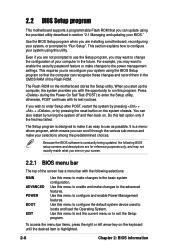
.... Use this program. It is constantly being updated, the following selections: MAIN ADVANCED POWER BOOT EXIT Use this utility. 2.2 BIOS Setup program This motherboard supports a programmable Flash ROM that the computer can recognize these changes and record them in the CMOS RAM... sub-menus and make changes to the power management settings. For example, you are installing a motherboard, reconfiguring your screen. 2.2.1 BIOS menu bar The top of your computer in section "2.1 Managing and updating your system using the provided utility described in the future....
.... Use this program. It is constantly being updated, the following selections: MAIN ADVANCED POWER BOOT EXIT Use this utility. 2.2 BIOS Setup program This motherboard supports a programmable Flash ROM that the computer can recognize these changes and record them in the CMOS RAM... sub-menus and make changes to the power management settings. For example, you are installing a motherboard, reconfiguring your screen. 2.2.1 BIOS menu bar The top of your computer in section "2.1 Managing and updating your system using the provided utility described in the future....


