
Motherboard DIY Troubleshooting Guide
Page 34
ASUS EZ Flash V1.00 Copyright (C) 2002, ASUSTeK COMPUTER INC. [Onboard BIOS Information] BIOS Version : ASUS P4PE-X ACPI BIOS Revision 1002 BIOS Model : P4PE-X BIOS Built Date : 04/16/02 Please Enter File Name for NEW BIOS: _ *Note: EZ Flash will copy file from A:\, Press [ESC] to reboot 2-2
ASUS EZ Flash V1.00 Copyright (C) 2002, ASUSTeK COMPUTER INC. [Onboard BIOS Information] BIOS Version : ASUS P4PE-X ACPI BIOS Revision 1002 BIOS Model : P4PE-X BIOS Built Date : 04/16/02 Please Enter File Name for NEW BIOS: _ *Note: EZ Flash will copy file from A:\, Press [ESC] to reboot 2-2

Motherboard DIY Troubleshooting Guide
Page 35
Continue to update the BIOS (Y/N)? _ Flash Memory: SST XXXXXXX Update Main BIOS area (Y/N)? _ 2-3 [BIOS Information in File] BIOS Version: P4PE-X Boot Block WARNING!
Continue to update the BIOS (Y/N)? _ Flash Memory: SST XXXXXXX Update Main BIOS area (Y/N)? _ 2-3 [BIOS Information in File] BIOS Version: P4PE-X Boot Block WARNING!

P4PE-X User Manual
Page 3
Features Contents Notices v Safety information vi About this guide vii ASUS contact information viii P4PE-X specifications summary ix Chapter 1: Product introduction 1.1 Welcome 1-2 1.2 Package contents 1-2 1.3 Special features 1-3 1.4 Motherboard components 1-4 1.5 Motherboard layout 1-7 ... for this motherboard 1-14 1.11 Jumpers 1-15 1.12 Connectors 1-16 Chapter 2: BIOS information 2.1 Managing and updating your BIOS 2-2 2.1.1 Using ASUS EZ Flash to update the BIOS 2-2 2.1.2 Using AFLASH to update the BIOS 2-4 2.1.3 CrashFree BIOS feature 2-7 2.1.4 BIOS beep codes 2-7 iii
Features Contents Notices v Safety information vi About this guide vii ASUS contact information viii P4PE-X specifications summary ix Chapter 1: Product introduction 1.1 Welcome 1-2 1.2 Package contents 1-2 1.3 Special features 1-3 1.4 Motherboard components 1-4 1.5 Motherboard layout 1-7 ... for this motherboard 1-14 1.11 Jumpers 1-15 1.12 Connectors 1-16 Chapter 2: BIOS information 2.1 Managing and updating your BIOS 2-2 2.1.1 Using ASUS EZ Flash to update the BIOS 2-2 2.1.2 Using AFLASH to update the BIOS 2-4 2.1.3 CrashFree BIOS feature 2-7 2.1.4 BIOS beep codes 2-7 iii

P4PE-X User Manual
Page 4
Safeguards Contents 2.2 BIOS Setup program 2-8 2.2.1 BIOS menu bar 2-8 2.2.2 Legend bar 2-9 2.3 Main Menu 2-10 2.3.1 Primary and Secondary Master/Slave 2-12 2.3.2 Keyboard Features 2-14 2.4 Advanced Menu 2-15 2.4.1 Chip Configuration 2-18 2.4.2 I/O Device Configuration 2-20 2.4.3 ... 2-27 2.6 Boot Menu 2-28 2.7 Exit Menu 2-30 Chapter 3: Software support 3.1 Install an operating system 3-2 3.2 Support CD information 3-2 3.2.1 Running the support CD 3-2 3.2.2 Drivers menu 3-3 3.2.3 Utilities menu 3-4 3.2.4 ASUS Contact Information 3-5 iv
Safeguards Contents 2.2 BIOS Setup program 2-8 2.2.1 BIOS menu bar 2-8 2.2.2 Legend bar 2-9 2.3 Main Menu 2-10 2.3.1 Primary and Secondary Master/Slave 2-12 2.3.2 Keyboard Features 2-14 2.4 Advanced Menu 2-15 2.4.1 Chip Configuration 2-18 2.4.2 I/O Device Configuration 2-20 2.4.3 ... 2-27 2.6 Boot Menu 2-28 2.7 Exit Menu 2-30 Chapter 3: Software support 3.1 Install an operating system 3-2 3.2 Support CD information 3-2 3.2.1 Running the support CD 3-2 3.2.2 Drivers menu 3-3 3.2.3 Utilities menu 3-4 3.2.4 ASUS Contact Information 3-5 iv

P4PE-X User Manual
Page 10
x P4PE-X specifications summary BIOS features Industry standard Manageability Form Factor Support CD contents 2Mb Flash ROM, Award BIOS, TCAV, PnP, DMI2.0, SM BIOS2.3, CrashFree BIOS, ASUS EZ Flash PCI 2.2, USB 2.0 WfM 2.0. DMI 2.0, WOL/WOR by PME, chassis intrusion, SMBus ATX form factor: 12 in x 9.0 in (30.5 cm x 22.9 cm) Device drivers ASUS PC Probe ASUS LiveUpdate Trend Micro™ PC-cillin 2002 anti-virus software * Specifications are subject to change without notice.
x P4PE-X specifications summary BIOS features Industry standard Manageability Form Factor Support CD contents 2Mb Flash ROM, Award BIOS, TCAV, PnP, DMI2.0, SM BIOS2.3, CrashFree BIOS, ASUS EZ Flash PCI 2.2, USB 2.0 WfM 2.0. DMI 2.0, WOL/WOR by PME, chassis intrusion, SMBus ATX form factor: 12 in x 9.0 in (30.5 cm x 22.9 cm) Device drivers ASUS PC Probe ASUS LiveUpdate Trend Micro™ PC-cillin 2002 anti-virus software * Specifications are subject to change without notice.

P4PE-X User Manual
Page 13
...module. Onboard LAN solution The motherboard has the BroadCom® BCM4401 chipset onboard to clear the CMOS data. ASUS EZ Flash BIOS With the ASUS EZ Flash, you to restore the original BIOS data from 12 Mbps on USB 1.1 to buy a replacement ROM chip. No need to a fast ...Recall) When the system hangs due to overclocking failure, there is no need to open the case to support 10BASE-T/100BASE-TX networking protocol. ASUS P4PE-X motherboard user guide 1-3 USB 2.0 technology The motherboard implements the new Universal Serial Bus (USB) 2.0 specification, extending the connection speed from a...
...module. Onboard LAN solution The motherboard has the BroadCom® BCM4401 chipset onboard to clear the CMOS data. ASUS EZ Flash BIOS With the ASUS EZ Flash, you to restore the original BIOS data from 12 Mbps on USB 1.1 to buy a replacement ROM chip. No need to a fast ...Recall) When the system hangs due to overclocking failure, there is no need to open the case to support 10BASE-T/100BASE-TX networking protocol. ASUS P4PE-X motherboard user guide 1-3 USB 2.0 technology The motherboard implements the new Universal Serial Bus (USB) 2.0 specification, extending the connection speed from a...
P4PE-X User Manual
Page 15
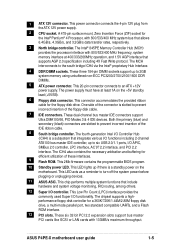
... with 800/533/400 MHz frequency, system memory interface at least 1A on the motherboard. This 2Mb firmware contains the programmable BIOS program. 10 Standby power LED. These six 32-bit PCI 2.2 expansion slots support bus master PCI cards like SCSI or LAN... DMA100/66, PIO Modes 3 & 4 IDE devices. This chip performs multiple system functions that supports AGP 2.0 specification including 4X Fast Write protocol. ASUS P4PE-X motherboard user guide 1-5 1 ATX 12V connector. This connector accommodates the provided ribbon cable for a 360K/720K/1.44M/2.88M floppy disk drive, a...
... with 800/533/400 MHz frequency, system memory interface at least 1A on the motherboard. This 2Mb firmware contains the programmable BIOS program. 10 Standby power LED. These six 32-bit PCI 2.2 expansion slots support bus master PCI cards like SCSI or LAN... DMA100/66, PIO Modes 3 & 4 IDE devices. This chip performs multiple system functions that supports AGP 2.0 specification including 4X Fast Write protocol. ASUS P4PE-X motherboard user guide 1-5 1 ATX 12V connector. This connector accommodates the provided ribbon cable for a 360K/720K/1.44M/2.88M floppy disk drive, a...

P4PE-X User Manual
Page 20
... supports Hyper-Threading Techonology. 3. For more information on Intel® Hyper-Threading Technology 1. Power up the system and enter BIOS Setup. Notes on Hyper-Threading Technology, visit www.intel.com/ info/hyperthreading. To use the Hyper-Threading compliler to Enabled....CPU has a gold triangular mark on one corner. Hyper-Threading Technology is designed for the Intel® Pentium® 4 Processor in BIOS before installing a supported operating system. 4. This mark indicates the processor Pin 1 that the item Hyper-Threading Technology is recommended that supports...
... supports Hyper-Threading Techonology. 3. For more information on Intel® Hyper-Threading Technology 1. Power up the system and enter BIOS Setup. Notes on Hyper-Threading Technology, visit www.intel.com/ info/hyperthreading. To use the Hyper-Threading compliler to Enabled....CPU has a gold triangular mark on one corner. Hyper-Threading Technology is designed for the Intel® Pentium® 4 Processor in BIOS before installing a supported operating system. 4. This mark indicates the processor Pin 1 that the item Hyper-Threading Technology is recommended that supports...
P4PE-X User Manual
Page 24
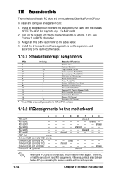
... Data Processor 14* 9 Primary IDE Channel 15* 10 Secondary IDE Channel * These IRQs are usually available for ISA or PCI devices. 1.10.2 IRQ assignments for BIOS information. 3. shared - - shared - - - - - - - - - -- - - - - -- - shared - - shared - - - 1.10 Expansion ... F GH - - - shared - - - - - - shared - - - - - - used - - - - When using PCI cards on the system and change the necessary BIOS settings, if any. Otherwise, conflicts arise between the two PCI groups making the system unstable and the card inoperable. 1-14 Chapter 1: Product introduction
... Data Processor 14* 9 Primary IDE Channel 15* 10 Secondary IDE Channel * These IRQs are usually available for ISA or PCI devices. 1.10.2 IRQ assignments for BIOS information. 3. shared - - shared - - - - - - - - - -- - - - - -- - shared - - shared - - - 1.10 Expansion ... F GH - - - shared - - - - - - shared - - - - - - used - - - - When using PCI cards on the system and change the necessary BIOS settings, if any. Otherwise, conflicts arise between the two PCI groups making the system unstable and the card inoperable. 1-14 Chapter 1: Product introduction

P4PE-X User Manual
Page 25
... the cap will cause system boot failure! ® P4PE-X CLRTC 12 23 P4PE-X Clear RTC RAM Disable (Default) Enable You do...allows clearing the Real Time Clock (RTC) RAM in the BIOS (see section 2.5.1 Power Up Control). Except when clearing ... down the key during the boot process and enter BIOS setup to wake up feature. Set this jumper to... data. Hold down and reboot the system so BIOS can clear the CMOS memory of date, time,... key on CLRTC1 jumper default position. KBPWR1 12 23 P4PE-X +5V +5VSB ® (Default) P4PE-X Keyboard Power Setting 2. Turn OFF the computer and ...
... the cap will cause system boot failure! ® P4PE-X CLRTC 12 23 P4PE-X Clear RTC RAM Disable (Default) Enable You do...allows clearing the Real Time Clock (RTC) RAM in the BIOS (see section 2.5.1 Power Up Control). Except when clearing ... down the key during the boot process and enter BIOS setup to wake up feature. Set this jumper to... data. Hold down and reboot the system so BIOS can clear the CMOS memory of date, time,... key on CLRTC1 jumper default position. KBPWR1 12 23 P4PE-X +5V +5VSB ® (Default) P4PE-X Keyboard Power Setting 2. Turn OFF the computer and ...

P4PE-X User Manual
Page 27
...BIOS supports specific device bootup. Pin 20 on each IDE connector is intentional. ® P4PE-X NOTE: Orient the red markings (usually zigzag) on the UltraDMA cable connector. This prevents incorrect orientation when you must configure the second drive as a slave device by setting its jumper accordingly. FLOPPY1 ® P4PE...to the hard disk documentation for the secondary IDE connector. 1. SEC_IDE PRI_IDE P4PE-X IDE Connectors PIN 1 PIN 1 4. PIN 1 P4PE-X Floppy Disk Drive Connector ASUS P4PE-X motherboard user guide 1-17 If you connect nonUltraDMA/100/66 devices to...
...BIOS supports specific device bootup. Pin 20 on each IDE connector is intentional. ® P4PE-X NOTE: Orient the red markings (usually zigzag) on the UltraDMA cable connector. This prevents incorrect orientation when you must configure the second drive as a slave device by setting its jumper accordingly. FLOPPY1 ® P4PE...to the hard disk documentation for the secondary IDE connector. 1. SEC_IDE PRI_IDE P4PE-X IDE Connectors PIN 1 PIN 1 4. PIN 1 P4PE-X Floppy Disk Drive Connector ASUS P4PE-X motherboard user guide 1-17 If you connect nonUltraDMA/100/66 devices to...

P4PE-X User Manual
Page 32
...) This 2-pin connector connects to hear system beeps and warnings. • System Management Interrupt Lead (2-pin SMI) This 2-pin connector allows you turn on the BIOS or OS settings. Attach the casemounted suspend switch to the system power LED. Pressing the power switch while in sleep mode. • Keyboard Lock Lead...
...) This 2-pin connector connects to hear system beeps and warnings. • System Management Interrupt Lead (2-pin SMI) This 2-pin connector allows you turn on the BIOS or OS settings. Attach the casemounted suspend switch to the system power LED. Pressing the power switch while in sleep mode. • Keyboard Lock Lead...

P4PE-X User Manual
Page 33
Detailed descriptions of the BIOS parameters are also provided. BIOS information Chapter 2 This chapter tells how to change system settings through the BIOS Setup menus.
Detailed descriptions of the BIOS parameters are also provided. BIOS information Chapter 2 This chapter tells how to change system settings through the BIOS Setup menus.

P4PE-X User Manual
Page 34
... drive. Follow these steps to reboot The BIOS information in the BIOS firmware so it is for NEW BIOS: _ *Note: EZ Flash will receive the error message, "WARNING! Device not ready." ASUS EZ Flash V1.00 Copyright (C) 2002, ASUSTeK COMPUTER INC. [Onboard BIOS Information] BIOS Version : ASUS P4PE-X ACPI BIOS Revision 1002 BIOS Model : P4PE-X BIOS Built Date : 04/16/02 Please...
... drive. Follow these steps to reboot The BIOS information in the BIOS firmware so it is for NEW BIOS: _ *Note: EZ Flash will receive the error message, "WARNING! Device not ready." ASUS EZ Flash V1.00 Copyright (C) 2002, ASUSTeK COMPUTER INC. [Onboard BIOS Information] BIOS Version : ASUS P4PE-X ACPI BIOS Revision 1002 BIOS Model : P4PE-X BIOS Built Date : 04/16/02 Please...

P4PE-X User Manual
Page 35
... screen and reboots the system without updating the BIOS. Doing so may cause system boot failure. 8. ASUS P4PE-X motherboard user guide 2-3 EZ Flash will automatically access drive A to continue with the new BIOS. Press . 6. At the above prompt, type Y to look for NEW BIOS: _", type in the BIOS file name that you accidentally typed in a wrong...
... screen and reboots the system without updating the BIOS. Doing so may cause system boot failure. 8. ASUS P4PE-X motherboard user guide 2-3 EZ Flash will automatically access drive A to continue with the new BIOS. Press . 6. At the above prompt, type Y to look for NEW BIOS: _", type in the BIOS file name that you accidentally typed in a wrong...

P4PE-X User Manual
Page 36
...work in DOS mode. It does not work with certain memory drivers that may be programmed by the Flash Memory Writer utility. 2-4 Chapter 2: BIOS information Larger numbers represent a newer BIOS file. 1. Type FORMAT A:/S at the DOS prompt to the boot disk you created. It is not supported by the ACPI...on the upper left-hand corner of the code displayed on the motherboard. In DOS mode, type A:\AFLASH to run AFLASH. To determine the BIOS version of your motherboard, check the last four numbers of your CD-ROM drive) to copy AFLASH.EXE to create a bootable system disk. Reboot...
...work in DOS mode. It does not work with certain memory drivers that may be programmed by the Flash Memory Writer utility. 2-4 Chapter 2: BIOS information Larger numbers represent a newer BIOS file. 1. Type FORMAT A:/S at the DOS prompt to the boot disk you created. It is not supported by the ACPI...on the upper left-hand corner of the code displayed on the motherboard. In DOS mode, type A:\AFLASH to run AFLASH. To determine the BIOS version of your motherboard, check the last four numbers of your CD-ROM drive) to copy AFLASH.EXE to create a bootable system disk. Reboot...

P4PE-X User Manual
Page 37
Boot from the Main menu and press . ASUS P4PE-X motherboard user guide 2-5 Type a filename and the path, for example, A:\XXX- Download an updated ASUS BIOS file from the Internet (WWW or FTP) (see ASUS CONTACT INFORMATION on page viii for details) and save to File from the floppy disk. 3. At the ...Main Menu, type 2 then press . The Save Current BIOS To File screen appears. 6. Type the...
Boot from the Main menu and press . ASUS P4PE-X motherboard user guide 2-5 Type a filename and the path, for example, A:\XXX- Download an updated ASUS BIOS file from the Internet (WWW or FTP) (see ASUS CONTACT INFORMATION on page viii for details) and save to File from the floppy disk. 3. At the ...Main Menu, type 2 then press . The Save Current BIOS To File screen appears. 6. Type the...

P4PE-X User Manual
Page 38
... boot. When prompted to confirm the BIOS update, press Y to continue. 6. If you encounter problems while updating the new BIOS, DO NOT turn off the system because this happens, call the ASUS service center for support. 2-6 Chapter 2: BIOS information When the programming is not able... to successfully update a complete BIOS file, the system may cause boot problems. ...
... boot. When prompted to confirm the BIOS update, press Y to continue. 6. If you encounter problems while updating the new BIOS, DO NOT turn off the system because this happens, call the ASUS service center for support. 2-6 Chapter 2: BIOS information When the programming is not able... to successfully update a complete BIOS file, the system may cause boot problems. ...

P4PE-X User Manual
Page 39
... appears during POST No DRAM installed or detected Video card not found or video card memory bad CPU overheated; Follow the BIOS update procedure in an endless loop One long beep followed by three short beeps High frequency beeps when system is working Meaning... one that the computer boots from a floppy disk and update the BIOS in section 2.1.2, and should contain the AFLASH.EXE utility. 3. System running at a lower frequency ASUS P4PE-X motherboard user guide 2-7 2.1.3 CrashFree BIOS feature The CrashFree BIOS feature allows you to boot the computer from the floppy disk. 2....
... appears during POST No DRAM installed or detected Video card not found or video card memory bad CPU overheated; Follow the BIOS update procedure in an endless loop One long beep followed by three short beeps High frequency beeps when system is working Meaning... one that the computer boots from a floppy disk and update the BIOS in section 2.1.2, and should contain the AFLASH.EXE utility. 3. System running at a lower frequency ASUS P4PE-X motherboard user guide 2-7 2.1.3 CrashFree BIOS feature The CrashFree BIOS feature allows you to boot the computer from the floppy disk. 2....
P4PE-X User Manual
Page 40
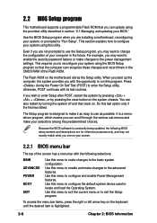
... on. You can scroll through the various sub-menus and make your selections among the predetermined choices. It is highlighted. 2-8 Chapter 2: BIOS information Use this menu to configure the default system device used to run this utility. Press during the Power-On Self Test (POST) ...reconfiguring your system, or prompted to the power management settings. Use this menu to enable and make changes to "Run Setup". Use the BIOS Setup program when you see on the motherboard stores the Setup utility. This section explains how to the basic system configuration. The Setup program...
... on. You can scroll through the various sub-menus and make your selections among the predetermined choices. It is highlighted. 2-8 Chapter 2: BIOS information Use this menu to configure the default system device used to run this utility. Press during the Power-On Self Test (POST) ...reconfiguring your system, or prompted to the power management settings. Use this menu to enable and make changes to "Run Setup". Use the BIOS Setup program when you see on the motherboard stores the Setup utility. This section explains how to the basic system configuration. The Setup program...


