
P4GE-VM user manual E1251
Page 3
Features Contents Notices v Safety information vi About this guide vii ASUS contact information viii P4GE-VM specifications summary ix Chapter 1: Product introduction 1.1 Welcome 1-2 1.2 Package contents 1-2 1.3 Motherboard components 1-3 1.4 Motherboard layout... Switches and jumpers 1-13 1.11 Connectors 1-16 Chapter 2: BIOS information 2.1 Managing and updating your BIOS 2-2 2.1.1 Using ASUS EZ Flash to update the BIOS 2-2 2.1.2 Using AFLASH to update the BIOS 2-4 2.1.3 CrashFree BIOS feature 2-7 2.1.4 BIOS beep codes 2-7 2.2 BIOS Setup program 2-8 2.2.1 BIOS menu bar 2-8 iii
Features Contents Notices v Safety information vi About this guide vii ASUS contact information viii P4GE-VM specifications summary ix Chapter 1: Product introduction 1.1 Welcome 1-2 1.2 Package contents 1-2 1.3 Motherboard components 1-3 1.4 Motherboard layout... Switches and jumpers 1-13 1.11 Connectors 1-16 Chapter 2: BIOS information 2.1 Managing and updating your BIOS 2-2 2.1.1 Using ASUS EZ Flash to update the BIOS 2-2 2.1.2 Using AFLASH to update the BIOS 2-4 2.1.3 CrashFree BIOS feature 2-7 2.1.4 BIOS beep codes 2-7 2.2 BIOS Setup program 2-8 2.2.1 BIOS menu bar 2-8 iii

P4GE-VM user manual E1251
Page 9
P4GE-VM specifications summary CPU Chipset Front Side Bus (FSB) Memory Expansion slots...-ECC DDR DIMMs 1 x AGP 4X (1.5V only) 3 x PCI Integrated 3D graphics controller in 82845GE chipset Supports ASUS DVI-845 graphics card (purchased separately) 2 x UltraDMA 100/66/33 connectors RealTek ALC650 6-channel audio CODEC Intel®...; 82562ET 10/100 Mbps Fast Ethernet controller Power Loss Restart Digital audio via an S/PDIF Out inteface AGP warning LED ASUS EZ Flash ASUS Q-Fan Technology CrashFree BIOS 1 x Parallel port 1 x Serial port 1 x Video port 1 x PS/2 keyboard port 1 x PS/2 mouse port...
P4GE-VM specifications summary CPU Chipset Front Side Bus (FSB) Memory Expansion slots...-ECC DDR DIMMs 1 x AGP 4X (1.5V only) 3 x PCI Integrated 3D graphics controller in 82845GE chipset Supports ASUS DVI-845 graphics card (purchased separately) 2 x UltraDMA 100/66/33 connectors RealTek ALC650 6-channel audio CODEC Intel®...; 82562ET 10/100 Mbps Fast Ethernet controller Power Loss Restart Digital audio via an S/PDIF Out inteface AGP warning LED ASUS EZ Flash ASUS Q-Fan Technology CrashFree BIOS 1 x Parallel port 1 x Serial port 1 x Video port 1 x PS/2 keyboard port 1 x PS/2 mouse port...

P4GE-VM user manual E1251
Page 10
x DMI 2.0, WOL/WOR by PME, chassis intrusion, SMBus Micro-ATX form factor: 9.6 in x 8.6 in (24.5 cm x 21.9 cm) Device drivers ASUS PC Probe ASUS LiveUpdate Trend Micro™ PC-cillin 2002 anti-virus software * Specifications are subject to change without notice. P4GE-VM specifications summary BIOS features Industry standard Manageability Form Factor Support CD contents 2Mb Flash ROM, Award BIOS, TCAV, PnP, DMI2.0, WfM2.0, SM BIOS2.3, CrashFree BIOS, ASUS EZ Flash PCI 2.2, USB 2.0 WfM 2.0.
x DMI 2.0, WOL/WOR by PME, chassis intrusion, SMBus Micro-ATX form factor: 9.6 in x 8.6 in (24.5 cm x 21.9 cm) Device drivers ASUS PC Probe ASUS LiveUpdate Trend Micro™ PC-cillin 2002 anti-virus software * Specifications are subject to change without notice. P4GE-VM specifications summary BIOS features Industry standard Manageability Form Factor Support CD contents 2Mb Flash ROM, Award BIOS, TCAV, PnP, DMI2.0, WfM2.0, SM BIOS2.3, CrashFree BIOS, ASUS EZ Flash PCI 2.2, USB 2.0 WfM 2.0.

P4GE-VM user manual E1251
Page 14
... of the floppy disk cable. 9 IDE connectors. This connector accommodates the provided ribbon cable for efficient utilization of these interfaces. 12 ASUS ASIC. The ICH4 also contains the necessary arbitration and buffering for the floppy disk drive. This 5-pin Dual Inline Package (DIP) ...you to an ATX +12V power supply. The power supply must have at 2.2GB/s or 1.6GB/s. This 2Mb firmware contains the programmable BIOS program. 11 South bridge controller. 1 DIP switches. The integrated graphics accelerator delivers 3D/2D video capabilities and a high bandwidth access to the...
... of the floppy disk cable. 9 IDE connectors. This connector accommodates the provided ribbon cable for efficient utilization of these interfaces. 12 ASUS ASIC. The ICH4 also contains the necessary arbitration and buffering for the floppy disk drive. This 5-pin Dual Inline Package (DIP) ...you to an ATX +12V power supply. The power supply must have at 2.2GB/s or 1.6GB/s. This 2Mb firmware contains the programmable BIOS program. 11 South bridge controller. 1 DIP switches. The integrated graphics accelerator delivers 3D/2D video capabilities and a high bandwidth access to the...
P4GE-VM user manual E1251
Page 19
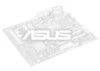
... the 478-pin package with 512KB L2 cache on this motherboard: 1. Gold Mark Incorrect installation of 4.2GB/s and 3.2GB/s. ASUS P4GE-VM motherboard user guide 1-9 It is supported under Windows XP and Linux 2.4.x (kernel) and later versions only. Notes on Hyper-.... Hyper-Threading Technology is recommended that the item Hyper-Threading Technology is designed for the Intel® Pentium® 4 Processor in BIOS before installing a supported operating system. 5. 1.7 Central Processing Unit (CPU) 1.7.1 Overview The motherboard comes with Hyper-Threading Technology. 2....
... the 478-pin package with 512KB L2 cache on this motherboard: 1. Gold Mark Incorrect installation of 4.2GB/s and 3.2GB/s. ASUS P4GE-VM motherboard user guide 1-9 It is supported under Windows XP and Linux 2.4.x (kernel) and later versions only. Notes on Hyper-.... Hyper-Threading Technology is recommended that the item Hyper-Threading Technology is designed for the Intel® Pentium® 4 Processor in BIOS before installing a supported operating system. 5. 1.7 Central Processing Unit (CPU) 1.7.1 Overview The motherboard comes with Hyper-Threading Technology. 2....
P4GE-VM user manual E1251
Page 22
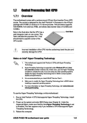
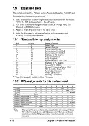
...- - - - - used - - - - - - Onboard USB 2.0 controller shared Onboard LAN (optional) - - - - When using PCI cards on the system and change the necessary BIOS settings, if any. To install and configure an expansion card: 1. PCI slot 2 - - - - - - used - - - - Install the drivers and/or software applications for the ... 15* 10 Secondary IDE Channel * These IRQs are usually available for ISA or PCI devices. 1.9.2 IRQ assignments for BIOS information. 3. Refer to the tables below. 4. Otherwise, conflicts will arise between the two PCI groups, making the system...
...- - - - - used - - - - - - Onboard USB 2.0 controller shared Onboard LAN (optional) - - - - When using PCI cards on the system and change the necessary BIOS settings, if any. To install and configure an expansion card: 1. PCI slot 2 - - - - - - used - - - - Install the drivers and/or software applications for the ... 15* 10 Secondary IDE Channel * These IRQs are usually available for ISA or PCI devices. 1.9.2 IRQ assignments for BIOS information. 3. Refer to the tables below. 4. Otherwise, conflicts will arise between the two PCI groups, making the system...

P4GE-VM user manual E1251
Page 24
... ATX power supply that can supply at least 1A on the keyboard (the default is set in the BIOS (see section 2.5.1 Power Up Control). ® P4GE-VM KBPWR1 2 1 +5V (Default) 3 2 +5VSB P4GE-VM Keyboard Power Setting 1-14 Chapter 1: Product introduction In JumperFree mode, set the switches as shown above..... 2. Set this jumper to pins 2-3 (+5VSB) if you to change CPU settings through the BIOS setup instead of using the DIP switches. ® J6 ON OFF SW1 ON 12345 P4GE-VM P4GE-VM JumperFree™ Mode Setting 12 Jumper Free 23 Jumper Mode (Default) The J6 jumper is the ...
... ATX power supply that can supply at least 1A on the keyboard (the default is set in the BIOS (see section 2.5.1 Power Up Control). ® P4GE-VM KBPWR1 2 1 +5V (Default) 3 2 +5VSB P4GE-VM Keyboard Power Setting 1-14 Chapter 1: Product introduction In JumperFree mode, set the switches as shown above..... 2. Set this jumper to pins 2-3 (+5VSB) if you to change CPU settings through the BIOS setup instead of using the DIP switches. ® J6 ON OFF SW1 ON 12345 P4GE-VM P4GE-VM JumperFree™ Mode Setting 12 Jumper Free 23 Jumper Mode (Default) The J6 jumper is the ...

P4GE-VM user manual E1251
Page 27
...cable. It is intentional. ® SEC_IDE PRI_IDE NOTE: Orient the red markings (usually zigzag) on the IDE ribbon cable to PIN 1. BIOS supports specific device bootup. one end to the motherboard, connect the other end to the floppy drive. (Pin 5 is removed to match ... Pin 20 on each IDE connector is removed to PIN 1. If you install two hard disks, you connect the cables. 2. P4GE-VM PIN 1 P4GE-VM IDE Connectors ASUS P4GE-VM motherboard user guide 1-17 This prevents incorrect orientation when you must configure the second drive as a slave device by setting its jumper...
...cable. It is intentional. ® SEC_IDE PRI_IDE NOTE: Orient the red markings (usually zigzag) on the IDE ribbon cable to PIN 1. BIOS supports specific device bootup. one end to the motherboard, connect the other end to the floppy drive. (Pin 5 is removed to match ... Pin 20 on each IDE connector is removed to PIN 1. If you install two hard disks, you connect the cables. 2. P4GE-VM PIN 1 P4GE-VM IDE Connectors ASUS P4GE-VM motherboard user guide 1-17 This prevents incorrect orientation when you must configure the second drive as a slave device by setting its jumper...

P4GE-VM user manual E1251
Page 32
... rebooting the system without turning off the system power. 1-22 Chapter 1: Product introduction The LED lights up when you turn on the BIOS or OS settings. Pressing the power switch while in sleep mode. • Keyboard Lock Lead (2-pin KEYLOCK) This 2-pin connector connects...® Keyboard Lock Speaker Power LED Connector +5 V PLED Keylock Ground +5V Ground Ground Speaker +5 V MLED ExtSMI# Ground PWR Ground Reset Ground P4GE-VM P4GE-VM System Panel Connectors Message LED SMI Lead Reset SW ATX Power Switch* * Requires an ATX power supply. • System Power LED Lead (3-1 pin...
... rebooting the system without turning off the system power. 1-22 Chapter 1: Product introduction The LED lights up when you turn on the BIOS or OS settings. Pressing the power switch while in sleep mode. • Keyboard Lock Lead (2-pin KEYLOCK) This 2-pin connector connects...® Keyboard Lock Speaker Power LED Connector +5 V PLED Keylock Ground +5V Ground Ground Speaker +5 V MLED ExtSMI# Ground PWR Ground Reset Ground P4GE-VM P4GE-VM System Panel Connectors Message LED SMI Lead Reset SW ATX Power Switch* * Requires an ATX power supply. • System Power LED Lead (3-1 pin...

P4GE-VM user manual E1251
Page 33
BIOS information Detailed descriptions of the BIOS parameters are also provided. Chapter 2 This chapter tells how to change system settings through the BIOS Setup menus.
BIOS information Detailed descriptions of the BIOS parameters are also provided. Chapter 2 This chapter tells how to change system settings through the BIOS Setup menus.

P4GE-VM user manual E1251
Page 34
... Device not ready." Follow these steps to reboot The BIOS information in case you need to a floppy disk. Reboot the computer. 3. ASUS EZ Flash V1.00 Copyright (C) 2002, ASUSTeK COMPUTER INC. [Onboard BIOS Information] BIOS Version : ASUS P4GE-VM ACPI BIOS Revision 1002 BIOS Model : P4GE-VM BIOS Built Date : 04/16/02 Please Enter File Name for reference only. What you...
... Device not ready." Follow these steps to reboot The BIOS information in case you need to a floppy disk. Reboot the computer. 3. ASUS EZ Flash V1.00 Copyright (C) 2002, ASUSTeK COMPUTER INC. [Onboard BIOS Information] BIOS Version : ASUS P4GE-VM ACPI BIOS Revision 1002 BIOS Model : P4GE-VM BIOS Built Date : 04/16/02 Please Enter File Name for reference only. What you...

P4GE-VM user manual E1251
Page 35
...! Continue to remove the message, then type in File] BIOS Version: P4GE-VM Boot Block WARNING! At the above prompt, type Y to reboot" appears. DO NOT shutdown or reset the system while updating the BIOS area! ASUS P4GE-VM motherboard user guide 2-3 The following message appears on screen. [BIOS Information in the correct file name. appears. Press to...
...! Continue to remove the message, then type in File] BIOS Version: P4GE-VM Boot Block WARNING! At the above prompt, type Y to reboot" appears. DO NOT shutdown or reset the system while updating the BIOS area! ASUS P4GE-VM motherboard user guide 2-3 The following message appears on screen. [BIOS Information in the correct file name. appears. Press to...

P4GE-VM user manual E1251
Page 36
... the code displayed on the motherboard. It is your CD-ROM drive) to copy AFLASH.EXE to create a bootable system disk. Larger numbers represent a newer BIOS file. 1. Reboot the computer from the hard drive. This file works only in DOS mode. DO NOT copy AUTOEXEC.BAT and CONFIG.SYS to run... AFLASH. AFLASH works only in DOS mode. In DOS mode, type A:\AFLASH to the disk. 2. BIOS setup must specify "Floppy" as the first item in the DOS prompt within Windows, and does not work with certain memory drivers that you boot...
... the code displayed on the motherboard. It is your CD-ROM drive) to copy AFLASH.EXE to create a bootable system disk. Larger numbers represent a newer BIOS file. 1. Reboot the computer from the hard drive. This file works only in DOS mode. DO NOT copy AUTOEXEC.BAT and CONFIG.SYS to run... AFLASH. AFLASH works only in DOS mode. In DOS mode, type A:\AFLASH to the disk. 2. BIOS setup must specify "Floppy" as the first item in the DOS prompt within Windows, and does not work with certain memory drivers that you boot...

P4GE-VM user manual E1251
Page 37
... INFORMATION on page viii for example, A:\XXX-XX.XXX, then press . Boot from the Main menu and press . ASUS P4GE-VM motherboard user guide 2-5 Save Current BIOS to more problems with the motherboard and you created earlier. 2. At the Main Menu, type 2 then press . Type the filename of your problems. Careless updating ...
... INFORMATION on page viii for example, A:\XXX-XX.XXX, then press . Boot from the Main menu and press . ASUS P4GE-VM motherboard user guide 2-5 Save Current BIOS to more problems with the motherboard and you created earlier. 2. At the Main Menu, type 2 then press . Type the filename of your problems. Careless updating ...

P4GE-VM user manual E1251
Page 38
If you encounter problems while updating the new BIOS, DO NOT turn off the system because this happens, call the ASUS service center for support. 2-6 Chapter 2: BIOS information If the Flash Memory Writer utility is not able to successfully update a complete BIOS file, the system may cause boot problems. Just repeat the process, and if...
If you encounter problems while updating the new BIOS, DO NOT turn off the system because this happens, call the ASUS service center for support. 2-6 Chapter 2: BIOS information If the Flash Memory Writer utility is not able to successfully update a complete BIOS file, the system may cause boot problems. Just repeat the process, and if...

P4GE-VM user manual E1251
Page 39
... the beeps. Turn on this motherboard, install a VGA card into the floppy drive, so that you will hear BIOS beeps. System running at a lower frequency ASUS P4GE-VM motherboard user guide 2-7 To use the CrashFree BIOS feature on the computer, and when prompted, place the bootable floppy disk into one that the computer boots from...
... the beeps. Turn on this motherboard, install a VGA card into the floppy drive, so that you will hear BIOS beeps. System running at a lower frequency ASUS P4GE-VM motherboard user guide 2-7 To use the CrashFree BIOS feature on the computer, and when prompted, place the bootable floppy disk into one that the computer boots from...

P4GE-VM user manual E1251
Page 40
... to make changes to use the Setup program, you with the opportunity to enter the Setup utility, otherwise, POST continues with the following BIOS setup screens and descriptions are not prompted to use as easy to the power management settings. Use this menu to make changes to locate.... Use this menu to exit the current menu or to change the configuration of your computer in section "2.1 Managing and updating your screen. 2.2.1 BIOS menu bar The top of the Flash ROM. This section explains how to configure and enable Power Management features. The Flash ROM on . Use...
... to make changes to use the Setup program, you with the opportunity to enter the Setup utility, otherwise, POST continues with the following BIOS setup screens and descriptions are not prompted to use as easy to the power management settings. Use this menu to make changes to locate.... Use this menu to exit the current menu or to change the configuration of your computer in section "2.1 Managing and updating your screen. 2.2.1 BIOS menu bar The top of the Flash ROM. This section explains how to configure and enable Power Management features. The Flash ROM on . Use...

P4GE-VM user manual E1251
Page 41
... in the window. The General Help screen lists the legend keys and their corresponding functions. ASUS P4GE-VM motherboard user guide 2-9 2.2.2 Legend bar At the bottom of a help In addition to the Item Specific Help window, the BIOS setup program also provides a General Help screen. You may launch this screen from any menu...Scroll bar When a scroll bar appears to the right of the Setup screen is more information to be displayed that will not fit in the BIOS Setup Jumps to the Exit menu or returns to the main menu from a sub-menu Selects the menu item to the left or right Moves...
... in the window. The General Help screen lists the legend keys and their corresponding functions. ASUS P4GE-VM motherboard user guide 2-9 2.2.2 Legend bar At the bottom of a help In addition to the Item Specific Help window, the BIOS setup program also provides a General Help screen. You may launch this screen from any menu...Scroll bar When a scroll bar appears to the right of the Setup screen is more information to be displayed that will not fit in the BIOS Setup Jumps to the Exit menu or returns to the main menu from a sub-menu Selects the menu item to the left or right Moves...

P4GE-VM user manual E1251
Page 42
... located to the right of each menu. Use the legend keys to enter values and move between the month, day, and year fields. 2-10 Chapter 2: BIOS information System Time [XX:XX:XX] Sets the system to 59). Valid values for month, day, and year are Hour: (00 to 23), Minute: (00...
... located to the right of each menu. Use the legend keys to enter values and move between the month, day, and year fields. 2-10 Chapter 2: BIOS information System Time [XX:XX:XX] Sets the system to 59). Valid values for month, day, and year are Hour: (00 to 23), Minute: (00...

P4GE-VM user manual E1251
Page 43
... and remove the button cell battery. Refer to section "2.1 Managing and updating your password, you did , the Supervisor password is set to eight alphanumeric characters. ASUS P4GE-VM motherboard user guide 2-11 Configuration options: [None] [360K, 5.25 in.] [1.2M , 5.25 in.] [720K , 3.5 in.] [1.44M, 3.5 in.] ...88M, 3.5 in.] Floppy 3 Mode Support [Disabled] This is now set to the configuration fields. The password is required to update the BIOS. To confirm the password, type the password again and press . If you can type up the system. You can clear it by the ...
... and remove the button cell battery. Refer to section "2.1 Managing and updating your password, you did , the Supervisor password is set to eight alphanumeric characters. ASUS P4GE-VM motherboard user guide 2-11 Configuration options: [None] [360K, 5.25 in.] [1.2M , 5.25 in.] [720K , 3.5 in.] [1.44M, 3.5 in.] ...88M, 3.5 in.] Floppy 3 Mode Support [Disabled] This is now set to the configuration fields. The password is required to update the BIOS. To confirm the password, type the password again and press . If you can type up the system. You can clear it by the ...


