Motherboard DIY Troubleshooting Guide
Page 4
... 4-17 4.4.2 I/O Device Configuration 4-19 4.4.3 PCI Configuration 4-21 4.5 Power Menu 4-24 4.5.1 Power Up Control 4-26 4.5.2 Hardware Monitor 4-28 4.6 Boot Menu 4-29 4.7 Exit Menu 4-31 Chapter 5: Software support 5-1 5.1 Install an operating system 5-1 5.1.1 Windows 98 first time installation 5-1 5.2 Support CD information 5-1 5.2.1 Running the support CD 5-1 5.2.2 Main menu 5-2 5.2.3 Software menu 5-3 5.2.4 Drivers menu 5-5 iv
... 4-17 4.4.2 I/O Device Configuration 4-19 4.4.3 PCI Configuration 4-21 4.5 Power Menu 4-24 4.5.1 Power Up Control 4-26 4.5.2 Hardware Monitor 4-28 4.6 Boot Menu 4-29 4.7 Exit Menu 4-31 Chapter 5: Software support 5-1 5.1 Install an operating system 5-1 5.1.1 Windows 98 first time installation 5-1 5.2 Support CD information 5-1 5.2.1 Running the support CD 5-1 5.2.2 Main menu 5-2 5.2.3 Software menu 5-3 5.2.4 Drivers menu 5-5 iv
Motherboard DIY Troubleshooting Guide
Page 8
.... viii It includes brief descriptions of the special attributes of the motherboard and the new technology it supports. • Chapter 2: Hardware information This chapter lists the hardware setup procedures that you need when installing the ASUS P4B-MX motherboard. About this guide This user guide contains the information you may encounter when reading this...
.... viii It includes brief descriptions of the special attributes of the motherboard and the new technology it supports. • Chapter 2: Hardware information This chapter lists the hardware setup procedures that you need when installing the ASUS P4B-MX motherboard. About this guide This user guide contains the information you may encounter when reading this...

Motherboard DIY Troubleshooting Guide
Page 10
...+886-2-2894-3449 info@asus.com.tw Technical Support Tel (English): +886-2-2890-7123 Tel (Chinese): +886-2-2890-7113 Fax: +886-2-2890-7698 Email: tsd@asus.com.tw Newsgroup: cscnews.asus.com.tw WWW: www.asus.com.tw FTP: ftp.asus.com.tw/pub/ASUS ASUS COMPUTER INTERNATIONAL (America) ...Center, Building 2 Newark, CA 94560, USA +1-510-608-4555 info-usa@asus.com.tw Technical Support Fax: +1-510-608-4555 BBS: +1-510-739-3774 Email: tsd@asus.com WWW: www.asus.com FTP: ftp.asus.com/pub/ASUS ASUS COMPUTER GmbH (Europe) Marketing Address: Fax: Email: Harkortstr. 25, 40880...
...+886-2-2894-3449 info@asus.com.tw Technical Support Tel (English): +886-2-2890-7123 Tel (Chinese): +886-2-2890-7113 Fax: +886-2-2890-7698 Email: tsd@asus.com.tw Newsgroup: cscnews.asus.com.tw WWW: www.asus.com.tw FTP: ftp.asus.com.tw/pub/ASUS ASUS COMPUTER INTERNATIONAL (America) ...Center, Building 2 Newark, CA 94560, USA +1-510-608-4555 info-usa@asus.com.tw Technical Support Fax: +1-510-608-4555 BBS: +1-510-739-3774 Email: tsd@asus.com WWW: www.asus.com FTP: ftp.asus.com/pub/ASUS ASUS COMPUTER GmbH (Europe) Marketing Address: Fax: Email: Harkortstr. 25, 40880...
Motherboard DIY Troubleshooting Guide
Page 11
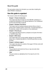
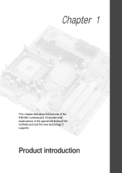
Product introduction Chapter 1 This chapter describes the features of the motherboard and the new technology it supports. It includes brief explanations of the special attributes of the P4B-MX motherboard.
Product introduction Chapter 1 This chapter describes the features of the motherboard and the new technology it supports. It includes brief explanations of the special attributes of the P4B-MX motherboard.

Motherboard DIY Troubleshooting Guide
Page 13
... contents Check your perfect vehicle to set a new benchmark for buying the ASUS® P4B-MX motherboard! Thank you start installing the motherboard, and hardware devices on it another standout in ) ASUS P4B-MX support CD ASUS 2-port USB module 80-conductor ribbon cable for UltraDMA/33/66/100 IDE... drives Ribbon cable for the following items. ASUS P4B-MX motherboard (micro-ATX form factor: 9.6-in x 9.6-in the long...
... contents Check your perfect vehicle to set a new benchmark for buying the ASUS® P4B-MX motherboard! Thank you start installing the motherboard, and hardware devices on it another standout in ) ASUS P4B-MX support CD ASUS 2-port USB module 80-conductor ribbon cable for UltraDMA/33/66/100 IDE... drives Ribbon cable for the following items. ASUS P4B-MX motherboard (micro-ATX form factor: 9.6-in x 9.6-in the long...
Motherboard DIY Troubleshooting Guide
Page 15
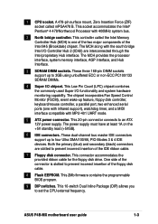
... interface, AGP interface, and Hub Interface. 3 SDRAM DIMM sockets. This 20-pin connector connects to prevent incorrect insertion of the connector is one with infrared support), watchdog timer, and a MIDI interface compatible with MPU-401 UART mode. 5 ATX power connector. This connector accommodates the provided ribbon cable for the floppy disk... south bridge Intel I /O functionality and system hardware monitoring capability. Both the primary (blue) and secondary (black) connectors are interconnected through the Intel proprietary Hub interface. ASUS P4B-MX motherboard user guide 1-3
... interface, AGP interface, and Hub Interface. 3 SDRAM DIMM sockets. This 20-pin connector connects to prevent incorrect insertion of the connector is one with infrared support), watchdog timer, and a MIDI interface compatible with MPU-401 UART mode. 5 ATX power connector. This connector accommodates the provided ribbon cable for the floppy disk... south bridge Intel I /O functionality and system hardware monitoring capability. Both the primary (blue) and secondary (black) connectors are interconnected through the Intel proprietary Hub interface. ASUS P4B-MX motherboard user guide 1-3
Motherboard DIY Troubleshooting Guide
Page 16
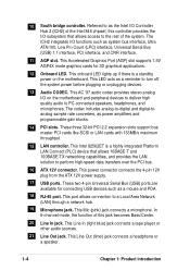
This Accelerated Graphics Port (AGP) slot supports 1.5V AGP4X mode graphics cards for connecting USB devices such as system bus interface, Ultra ATA/100, Low Pin Count (LPC) interface, Universal Serial Bus (... includes analog-to-digital and digital-toanalog sample rate converters, as a reminder to the rest of the system. These three 32-bit PCI 2.2 expansion slots support bus master PCI cards like SCSI or LAN cards with 133MB/s maximum throughput. 15 LAN controller. This Line Out (lime) jack connects a headphone or a speaker...
This Accelerated Graphics Port (AGP) slot supports 1.5V AGP4X mode graphics cards for connecting USB devices such as system bus interface, Ultra ATA/100, Low Pin Count (LPC) interface, Universal Serial Bus (... includes analog-to-digital and digital-toanalog sample rate converters, as a reminder to the rest of the system. These three 32-bit PCI 2.2 expansion slots support bus master PCI cards like SCSI or LAN cards with 133MB/s maximum throughput. 15 LAN controller. This Line Out (lime) jack connects a headphone or a speaker...
Motherboard DIY Troubleshooting Guide
Page 17
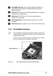
This connector supports a joystick or a game pad for playing games, and MIDI devices for a PS/2 keyboard. 26 PS/2 mouse port. This module should fit the retention mechanism that comes with the heatsink retention module base already installed. 22 Game/MIDI connector. Retention Module Base Figure 1-2 Pre-installed Heatsink Retention Module Base ASUS P4B-MX motherboard...
This connector supports a joystick or a game pad for playing games, and MIDI devices for a PS/2 keyboard. 26 PS/2 mouse port. This module should fit the retention mechanism that comes with the heatsink retention module base already installed. 22 Game/MIDI connector. Retention Module Base Figure 1-2 Pre-installed Heatsink Retention Module Base ASUS P4B-MX motherboard...

Motherboard DIY Troubleshooting Guide
Page 18
... the Northwood processor uses the 0.13 micron processor core with 512KB L2 cache for audio, video, and Internet applications. 1.4 Special features Latest processor technology The P4B-MX motherboard supports the latest Intel Pentium 4 478/ Northwood Processor, also known as P4, via a 478-pin surface mount ZIF socket.
... the Northwood processor uses the 0.13 micron processor core with 512KB L2 cache for audio, video, and Internet applications. 1.4 Special features Latest processor technology The P4B-MX motherboard supports the latest Intel Pentium 4 478/ Northwood Processor, also known as P4, via a 478-pin surface mount ZIF socket.
Motherboard DIY Troubleshooting Guide
Page 30
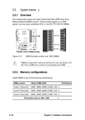
2.5 System memor y 2.5.1 Overview The motherboard comes with notches so that they fit in any of the following combinations. These sockets support up to avoid damaging the DIMM. 2.5.2 Memory configurations Install DIMMs in only one direction. DIMM Location 168-pin DIMM (SDR) Total Memory Socket 1 (... information DO NOT force a DIMM into a socket to 3GB system memory using unbuffered ECC or non-ECC PC100/133 DIMMs. 88 Pins ® P4B-MX P4B-MX 168-Pin DIMM Sockets 60 Pins 20 Pins Figure 2-13 DIMM Sockets Location and SDR DIMMs DIMMs are keyed with three Single Data Rate (SDR...
2.5 System memor y 2.5.1 Overview The motherboard comes with notches so that they fit in any of the following combinations. These sockets support up to avoid damaging the DIMM. 2.5.2 Memory configurations Install DIMMs in only one direction. DIMM Location 168-pin DIMM (SDR) Total Memory Socket 1 (... information DO NOT force a DIMM into a socket to 3GB system memory using unbuffered ECC or non-ECC PC100/133 DIMMs. 88 Pins ® P4B-MX P4B-MX 168-Pin DIMM Sockets 60 Pins 20 Pins Figure 2-13 DIMM Sockets Location and SDR DIMMs DIMMs are keyed with three Single Data Rate (SDR...

Motherboard DIY Troubleshooting Guide
Page 32
2.5.4 Removing a DIMM Follow these steps to unlock the DIMM. The DIMM might get damaged when it flips out with your fingers when pressing the retaining clips. Support the DIMM lightly with extra force. 2. Simultaneously press the retaining clips outward to remove a DIMM. 1. Remove the DIMM from the socket. Figure 2-16 Removing a DIMM 2-12 Chapter 2: Hardware information
2.5.4 Removing a DIMM Follow these steps to unlock the DIMM. The DIMM might get damaged when it flips out with your fingers when pressing the retaining clips. Support the DIMM lightly with extra force. 2. Simultaneously press the retaining clips outward to remove a DIMM. 1. Remove the DIMM from the socket. Figure 2-16 Removing a DIMM 2-12 Chapter 2: Hardware information
Motherboard DIY Troubleshooting Guide
Page 33
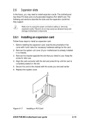
Failure to do so may need to install expansion cards. Keep the screw for the card. 2. Figure 2-17 Installing a PCI Card ASUS P4B-MX motherboard user guide 2-13 2.6 Expansion slots In the future, you may cause you physical injury and damage motherboard components. 2.6.1 Installing an expansion card Follow these...card to unplug the power cord before adding or removing expansion cards. The following sub-sections describe the slots and the expansion cards that they support. Replace the system cover. Make sure to the chassis with it and make the necessary hardware settings for later use .
Failure to do so may need to install expansion cards. Keep the screw for the card. 2. Figure 2-17 Installing a PCI Card ASUS P4B-MX motherboard user guide 2-13 2.6 Expansion slots In the future, you may cause you physical injury and damage motherboard components. 2.6.1 Installing an expansion card Follow these...card to unplug the power cord before adding or removing expansion cards. The following sub-sections describe the slots and the expansion cards that they support. Replace the system cover. Make sure to the chassis with it and make the necessary hardware settings for later use .
Motherboard DIY Troubleshooting Guide
Page 34
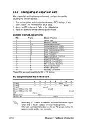
... BIOS setup. 2. Onboard USB controller HC1 shared AGP shared Onboard Audio - See Chapter 4 for the expansion card. Turn on shared slots, ensure that the drivers support "Share IRQ" or that the cards do not need IRQ assignments.
... BIOS setup. 2. Onboard USB controller HC1 shared AGP shared Onboard Audio - See Chapter 4 for the expansion card. Turn on shared slots, ensure that the drivers support "Share IRQ" or that the cards do not need IRQ assignments.
Motherboard DIY Troubleshooting Guide
Page 35
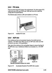
... cards such as a LAN card, SCSI card, USB card, and other cards that supports +1.5V AGP cards. Figure 2-18 Installed PCI Card 2.6.4 AGP slot This motherboard has an Accelerated Graphics Port (AGP) slot that comply with +1.5V specification. The .... 2.6.3 PCI slots There are three 32-bit PCI slots in this motherboard. When you ask for 1.5V Figure 2-19 Accelerated Graphics Port (AGP) Slot Location ASUS P4B-MX motherboard user guide 2-15 Take note of a +1.5V AGP card. ® P4B-MX P4B-MX Accelerated Graphics Port (AGP) Keyed for one with PCI specifications.
... cards such as a LAN card, SCSI card, USB card, and other cards that supports +1.5V AGP cards. Figure 2-18 Installed PCI Card 2.6.4 AGP slot This motherboard has an Accelerated Graphics Port (AGP) slot that comply with +1.5V specification. The .... 2.6.3 PCI slots There are three 32-bit PCI slots in this motherboard. When you ask for 1.5V Figure 2-19 Accelerated Graphics Port (AGP) Slot Location ASUS P4B-MX motherboard user guide 2-15 Take note of a +1.5V AGP card. ® P4B-MX P4B-MX Accelerated Graphics Port (AGP) Keyed for one with PCI specifications.

Motherboard DIY Troubleshooting Guide
Page 42
... the covered hole on each IDE connector is recommended that you connect the cables. 2. Secondary IDE Connector Primary IDE Connector ® P4B-MX P4B-MX IDE Connectors Figure 2-26 IDE Connectors NOTE: Orient the red markings (usually zigzag) on the UltraDMA/100/66 cable is intentional. ...cable to the hard disk documentation for the secondary IDE connector. 1. Primary/Secondary IDE connectors (40-1 pin IDE1/IDE2) This connector supports the provided UltraDMA/100/66 IDE hard disk ribbon cable. Connect the cable's blue connector to the primary (recommended) or secondary IDE ...
... the covered hole on each IDE connector is recommended that you connect the cables. 2. Secondary IDE Connector Primary IDE Connector ® P4B-MX P4B-MX IDE Connectors Figure 2-26 IDE Connectors NOTE: Orient the red markings (usually zigzag) on the UltraDMA/100/66 cable is intentional. ...cable to the hard disk documentation for the secondary IDE connector. 1. Primary/Secondary IDE connectors (40-1 pin IDE1/IDE2) This connector supports the provided UltraDMA/100/66 IDE hard disk ribbon cable. Connect the cable's blue connector to the primary (recommended) or secondary IDE ...

Motherboard DIY Troubleshooting Guide
Page 43
... Rotation +12V- ® P4B-MX SYSTEM_FAN Rotation -+12V PCI_FAN Rotation +12V- P4B-MX 12-Volt Cooling Fan Power Figure 2-28 CPU, System, and PCI Fan Connectors ASUS P4B-MX motherboard user guide 2-23 Do not forget to connect the fan cables to the ground pin. Floppy disk drive connector (34-1 pin FLOPPY) This connector supports the provided floppy...
... Rotation +12V- ® P4B-MX SYSTEM_FAN Rotation -+12V PCI_FAN Rotation +12V- P4B-MX 12-Volt Cooling Fan Power Figure 2-28 CPU, System, and PCI Fan Connectors ASUS P4B-MX motherboard user guide 2-23 Do not forget to connect the fan cables to the ground pin. Floppy disk drive connector (34-1 pin FLOPPY) This connector supports the provided floppy...

Motherboard DIY Troubleshooting Guide
Page 44
...+ 9: GND P4B-MX USB Header Figure 2-29 USB Header 6. IR 1 ® P4B-MX P4B-MX Infrared Module Connector Figure 2-30 Infrared Module Connector +5V (NC) IRRX GND IRTX Front View Back View IRTX +5V GND (NC) IRRX 2-24 Chapter 2: Hardware information 5. USB header (10-1 pin USB) If the USB ports on system chassis that support this feature...
...+ 9: GND P4B-MX USB Header Figure 2-29 USB Header 6. IR 1 ® P4B-MX P4B-MX Infrared Module Connector Figure 2-30 Infrared Module Connector +5V (NC) IRRX GND IRTX Front View Back View IRTX +5V GND (NC) IRRX 2-24 Chapter 2: Hardware information 5. USB header (10-1 pin USB) If the USB ports on system chassis that support this feature...
Motherboard DIY Troubleshooting Guide
Page 47
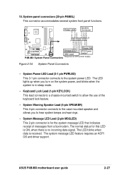
... Keylock +5V Ground Ground Speaker 20 1 +5 VSB MLED ExtSMI# Ground PWR Ground Reset Ground Reset SW ® P4B-MX Message LED ATX Power SMI Lead Switch* P4B-MX System Panel Connectors * Requires an ATX power supply. Figure 2-34 System Panel Connectors • System Power LED Lead ...connector is for this LED is ON, when there is received. The system message LED feature requires an ACPI OS and driver support. ASUS P4B-MX motherboard user guide 2-27 System panel connectors (20-pin PANEL) This connector accommodates several system front panel functions. The normal status...
... Keylock +5V Ground Ground Speaker 20 1 +5 VSB MLED ExtSMI# Ground PWR Ground Reset Ground Reset SW ® P4B-MX Message LED ATX Power SMI Lead Switch* P4B-MX System Panel Connectors * Requires an ATX power supply. Figure 2-34 System Panel Connectors • System Power LED Lead ...connector is for this LED is ON, when there is received. The system message LED feature requires an ACPI OS and driver support. ASUS P4B-MX motherboard user guide 2-27 System panel connectors (20-pin PANEL) This connector accommodates several system front panel functions. The normal status...
Motherboard DIY Troubleshooting Guide
Page 55
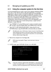
... the BIOS version of your motherboard, check the last four numbers of your BIOS 4.1.1 Using the computer system for the first time It is not supported by the ACPI BIOS and therefore, cannot be loaded when you need to reinstall the BIOS later. DO NOT copy AUTOEXEC.BAT and CONFIG.SYS... to the programmable flash ROM on the upper left-hand corner of the code displayed on the motherboard. Reboot the computer from the hard drive. ASUS P4B-MX motherboard user guide 4-1 It does not work in DOS mode. BIOS setup must specify "Floppy" as the first item in DOS mode. This file works...
... the BIOS version of your motherboard, check the last four numbers of your BIOS 4.1.1 Using the computer system for the first time It is not supported by the ACPI BIOS and therefore, cannot be loaded when you need to reinstall the BIOS later. DO NOT copy AUTOEXEC.BAT and CONFIG.SYS... to the programmable flash ROM on the upper left-hand corner of the code displayed on the motherboard. Reboot the computer from the hard drive. ASUS P4B-MX motherboard user guide 4-1 It does not work in DOS mode. BIOS setup must specify "Floppy" as the first item in DOS mode. This file works...

Motherboard DIY Troubleshooting Guide
Page 58
..., load the original BIOS file you encounter problems while updating the new BIOS, DO NOT turn off the system because this happens, call the ASUS service center for support. 4-4 Chapter 4: BIOS Setup Follow the onscreen instructions to program the new BIOS information into the Flash ROM. The utility starts to continue. If...
..., load the original BIOS file you encounter problems while updating the new BIOS, DO NOT turn off the system because this happens, call the ASUS service center for support. 4-4 Chapter 4: BIOS Setup Follow the onscreen instructions to program the new BIOS information into the Flash ROM. The utility starts to continue. If...


