Motherboard DIY Troubleshooting Guide
Page 4
... 2-18 2.8 Connectors 2-21 Chapter 3: Powering up 3-1 3.1 Starting up for the first time 3-1 3.3 Powering off the computer 3-2 Chapter 4: BIOS setup 4-1 4.1 Managing and updating your BIOS 4-1 4.1.1 Using the computer system for the first time 4-1 4.1.2 Updating BIOS procedures 4-3 4.2 BIOS Setup program 4-5 4.2.1 BIOS menu bar 4-6 4.2.2 Legend bar 4-6 4.3 Main menu 4-8 4.3.1 Primary & Secondary Master/Slave 4-9 4.3.2 Keyboard Features 4-13 4.4 Advanced Menu 4-15...
... 2-18 2.8 Connectors 2-21 Chapter 3: Powering up 3-1 3.1 Starting up for the first time 3-1 3.3 Powering off the computer 3-2 Chapter 4: BIOS setup 4-1 4.1 Managing and updating your BIOS 4-1 4.1.1 Using the computer system for the first time 4-1 4.1.2 Updating BIOS procedures 4-3 4.2 BIOS Setup program 4-5 4.2.1 BIOS menu bar 4-6 4.2.2 Legend bar 4-6 4.3 Main menu 4-8 4.3.1 Primary & Secondary Master/Slave 4-9 4.3.2 Keyboard Features 4-13 4.4 Advanced Menu 4-15...
Motherboard DIY Troubleshooting Guide
Page 8
... alphabetical list of the P4B-MX motherboard. viii Detailed descriptions of the BIOS parameters are also provided. • Chapter 5: Software support This chapter describes the contents of the support CD that comes with the motherboard package. • Glossary This part lists the technical terms that you need when installing the ASUS P4B-MX motherboard. How this...
... alphabetical list of the P4B-MX motherboard. viii Detailed descriptions of the BIOS parameters are also provided. • Chapter 5: Software support This chapter describes the contents of the support CD that comes with the motherboard package. • Glossary This part lists the technical terms that you need when installing the ASUS P4B-MX motherboard. How this...
Motherboard DIY Troubleshooting Guide
Page 15
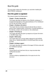
... bus. 2 North bridge controller. This 2Mb firmware contains the programmable BIOS program. 9 DIP switches. 1 CPU socket. This controller called mPGA478 B. The chipset incorporates Fan Speed Control Monitor (FSCM), event wake-up to four Ultra DMA/100/66, PIO Modes 3 & 4 IDE devices. ASUS P4B-MX motherboard user guide 1-3 The power supply must have at least...
... bus. 2 North bridge controller. This 2Mb firmware contains the programmable BIOS program. 9 DIP switches. 1 CPU socket. This controller called mPGA478 B. The chipset incorporates Fan Speed Control Monitor (FSCM), event wake-up to four Ultra DMA/100/66, PIO Modes 3 & 4 IDE devices. ASUS P4B-MX motherboard user guide 1-3 The power supply must have at least...
Motherboard DIY Troubleshooting Guide
Page 34
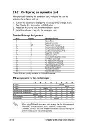
... - - Assign an IRQ to the tables below. 3. Onboard LAN - - - - When using PCI cards on the system and change the necessary BIOS settings, if any. Standard Interrupt Assignments IRQ Priority Standard Function 0 1 System Timer 1 2 Keyboard Controller 2 N/A Programmable Interrupt 3* 11 Communications Port (...HC0 - - - shared - - - See Chapter 4 for the expansion card. shared - - - - - Install the software drivers for information on BIOS setup. 2. shared - - - - Turn on shared slots, ensure that the drivers support "Share IRQ" or that the cards do not need IRQ ...
... - - Assign an IRQ to the tables below. 3. Onboard LAN - - - - When using PCI cards on the system and change the necessary BIOS settings, if any. Standard Interrupt Assignments IRQ Priority Standard Function 0 1 System Timer 1 2 Keyboard Controller 2 N/A Programmable Interrupt 3* 11 Communications Port (...HC0 - - - shared - - - See Chapter 4 for the expansion card. shared - - - - - Install the software drivers for information on BIOS setup. 2. shared - - - - Turn on shared slots, ensure that the drivers support "Share IRQ" or that the cards do not need IRQ ...
Motherboard DIY Troubleshooting Guide
Page 36
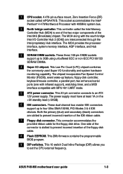
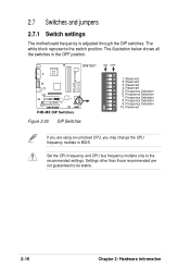
... only to be stable. 2-16 Chapter 2: Hardware information SW1801 ON OFF ON 1 2 3 4 5 6 7 8 9 10 ® P4B-MX P4B-MX DIP Switches Figure 2-20 DIP Switches 1. Frequency Selection 7. Reserved If you may change the CPU frequency multiple in the OFF position. Reserved 4. Frequency... Selection 6. Frequency Selection 9. The illustration below shows all the switches in BIOS. Reserved 2. 2.7 Switches and jumpers 2.7.1 Switch settings The motherboard frequency is adjusted through the DIP switches. Settings other than...
... only to be stable. 2-16 Chapter 2: Hardware information SW1801 ON OFF ON 1 2 3 4 5 6 7 8 9 10 ® P4B-MX P4B-MX DIP Switches Figure 2-20 DIP Switches 1. Frequency Selection 7. Reserved If you may change the CPU frequency multiple in the OFF position. Reserved 4. Frequency... Selection 6. Frequency Selection 9. The illustration below shows all the switches in BIOS. Reserved 2. 2.7 Switches and jumpers 2.7.1 Switch settings The motherboard frequency is adjusted through the DIP switches. Settings other than...
Motherboard DIY Troubleshooting Guide
Page 40
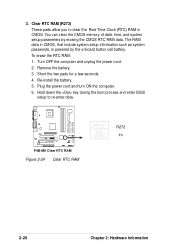
Re-install the battery. 5. Hold down the key during the boot process and enter BIOS setup to clear the Real Time Clock (RTC) RAM in CMOS, that include system setup information such as system passwords, is powered by erasing the ... date, time, and system setup parameters by the onboard button cell battery. 3. Clear RTC RAM (R272) These pads allow you to re-enter data. ® P4B-MX P4B-MX Clear RTC RAM Figure 2-24 Clear RTC RAM Intel I/O Controller Hub (ICH2) R272 2-20 Chapter 2: Hardware information
Re-install the battery. 5. Hold down the key during the boot process and enter BIOS setup to clear the Real Time Clock (RTC) RAM in CMOS, that include system setup information such as system passwords, is powered by erasing the ... date, time, and system setup parameters by the onboard button cell battery. 3. Clear RTC RAM (R272) These pads allow you to re-enter data. ® P4B-MX P4B-MX Clear RTC RAM Figure 2-24 Clear RTC RAM Intel I/O Controller Hub (ICH2) R272 2-20 Chapter 2: Hardware information

Motherboard DIY Troubleshooting Guide
Page 42
... each IDE connector is intentional. BIOS supports specific device bootup. If you install two hard disks, you connect the cables. 2. This prevents incorrect orientation when you must configure the second drive as a slave device by setting its jumper accordingly. Secondary IDE Connector Primary IDE Connector ® P4B-MX P4B-MX IDE Connectors Figure 2-26 IDE...
... each IDE connector is intentional. BIOS supports specific device bootup. If you install two hard disks, you connect the cables. 2. This prevents incorrect orientation when you must configure the second drive as a slave device by setting its jumper accordingly. Secondary IDE Connector Primary IDE Connector ® P4B-MX P4B-MX IDE Connectors Figure 2-26 IDE...

Motherboard DIY Troubleshooting Guide
Page 44
...Configuration" for use with IR. Use the five pins as shown in BIOS to a small opening on the rear panel are inadequate, a USB header is available for two additional USB ports. IR 1 ® P4B-MX P4B-MX Infrared Module Connector Figure 2-30 Infrared Module Connector +5V (NC) IRRX... module to the motherboard SIR connector according to an open slot in the chassis. ® P4B-MX USB 1 5 6 10 1: USB Power 2: USBP2- 3: USBP2+ 4: GND 5: NC 6: USB Power 7: USBP3- 8: USBP3+ 9: GND P4B-MX USB Header Figure 2-29 USB Header 6. Connect a 2-port USB connector set UART2 for details...
...Configuration" for use with IR. Use the five pins as shown in BIOS to a small opening on the rear panel are inadequate, a USB header is available for two additional USB ports. IR 1 ® P4B-MX P4B-MX Infrared Module Connector Figure 2-30 Infrared Module Connector +5V (NC) IRRX... module to the motherboard SIR connector according to an open slot in the chassis. ® P4B-MX USB 1 5 6 10 1: USB Power 2: USBP2- 3: USBP2+ 4: GND 5: NC 6: USB Power 7: USBP3- 8: USBP3+ 9: GND P4B-MX USB Header Figure 2-29 USB Header 6. Connect a 2-port USB connector set UART2 for details...
Motherboard DIY Troubleshooting Guide
Page 48
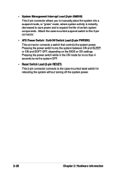
Pressing the power switch turns the system between ON and SLEEP, or ON and SOFT OFF, depending on the BIOS or OS settings. Pressing the power switch while in the ON mode for more than 4 seconds turns the system OFF. • Reset Switch Lead (2-pin ...
Pressing the power switch turns the system between ON and SLEEP, or ON and SOFT OFF, depending on the BIOS or OS settings. Pressing the power switch while in the ON mode for more than 4 seconds turns the system OFF. • Reset Switch Lead (2-pin ...

Motherboard DIY Troubleshooting Guide
Page 49
Chapter 3 This chapter describes the power up Powering up sequence and gives information on the BIOS beep codes.
Chapter 3 This chapter describes the power up Powering up sequence and gives information on the BIOS beep codes.

Motherboard DIY Troubleshooting Guide
Page 51
...or video card memory bad CPU overheated; External SCSI devices (starting with the last device on , hold down to enter BIOS Setup. At power on the chain) c. ASUS P4B-MX motherboard user guide 3-1 While the tests are running at the back of the chassis). 6. Follow the instructions in an endless...-on . Monitor b. After applying power, the power LED on the screen. If your retailer for the first time 1. System running , the BIOS beeps or additional messages appear on the system front panel case lights up or switch between orange and green after the system LED turns on...
...or video card memory bad CPU overheated; External SCSI devices (starting with the last device on , hold down to enter BIOS Setup. At power on the chain) c. ASUS P4B-MX motherboard user guide 3-1 While the tests are running at the back of the chassis). 6. Follow the instructions in an endless...-on . Monitor b. After applying power, the power LED on the screen. If your retailer for the first time 1. System running , the BIOS beeps or additional messages appear on the system front panel case lights up or switch between orange and green after the system LED turns on...
Motherboard DIY Troubleshooting Guide
Page 53
Detailed descriptions of the BIOS parameters are also provided. BIOS setup Chapter 4 This chapter tells how to change system settings through the BIOS Setup menus.
Detailed descriptions of the BIOS parameters are also provided. BIOS setup Chapter 4 This chapter tells how to change system settings through the BIOS Setup menus.
Motherboard DIY Troubleshooting Guide
Page 55
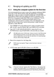
...to run AFLASH. Reboot the computer from the hard drive. To determine the BIOS version of your motherboard, check the last four numbers of the code displayed on the motherboard. ASUS P4B-MX motherboard user guide 4-1 AFLASH.EXE is a Flash Memory Writer utility that updates ...the BIOS by the Flash Memory Writer utility. Larger numbers represent a newer BIOS file. 1. Type COPY D:\AFLASH\AFLASH.EXE A:\ (assuming D ...
...to run AFLASH. Reboot the computer from the hard drive. To determine the BIOS version of your motherboard, check the last four numbers of the code displayed on the motherboard. ASUS P4B-MX motherboard user guide 4-1 AFLASH.EXE is a Flash Memory Writer utility that updates ...the BIOS by the Flash Memory Writer utility. Larger numbers represent a newer BIOS file. 1. Type COPY D:\AFLASH\AFLASH.EXE A:\ (assuming D ...
Motherboard DIY Troubleshooting Guide
Page 56
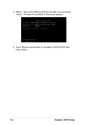
Select 1. Save Current BIOS to File from the Main menu and press . Type a filename and the path, for example, A:\XXX-XX.XXX, then press . 4-2 Chapter 4: BIOS Setup The Save Current BIOS To File screen appears. 6. 5.
Select 1. Save Current BIOS to File from the Main menu and press . Type a filename and the path, for example, A:\XXX-XX.XXX, then press . 4-2 Chapter 4: BIOS Setup The Save Current BIOS To File screen appears. 6. 5.
Motherboard DIY Troubleshooting Guide
Page 57
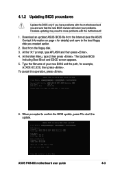
...4. ASUS P4B-MX motherboard user guide 4-3 The Update BIOS Including Boot Block and ESCD screen appears. 5. At the Main Menu, type 2 then press . When prompted to confirm the BIOS update, press Y to more problems with the motherboard and you created earlier. 2. 4.1.2 Updating BIOS procedures Update the BIOS only ...the filename of your problems. Careless updating may result to start the update. Download an updated ASUS BIOS file from the floppy disk. 3. Boot from the Internet (see the ASUS Contact Information on page x for details) and save to the boot floppy disk you are...
...4. ASUS P4B-MX motherboard user guide 4-3 The Update BIOS Including Boot Block and ESCD screen appears. 5. At the Main Menu, type 2 then press . When prompted to confirm the BIOS update, press Y to more problems with the motherboard and you created earlier. 2. 4.1.2 Updating BIOS procedures Update the BIOS only ...the filename of your problems. Careless updating may result to start the update. Download an updated ASUS BIOS file from the floppy disk. 3. Boot from the Internet (see the ASUS Contact Information on page x for details) and save to the boot floppy disk you are...

Motherboard DIY Troubleshooting Guide
Page 58
...is done, the message "Flashed Successfully" appears. 8. Follow the onscreen instructions to program the new BIOS information into the Flash ROM. If you saved to successfully update a complete BIOS file, the system may cause boot problems. Just repeat the process, and if the problem persists,... load the original BIOS file you encounter problems while updating the new BIOS, DO NOT turn off the system because this happens, call the ASUS service center for support. 4-4 Chapter 4: BIOS Setup 7. When the programming is updated automatically only when ...
...is done, the message "Flashed Successfully" appears. 8. Follow the onscreen instructions to program the new BIOS information into the Flash ROM. If you saved to successfully update a complete BIOS file, the system may cause boot problems. Just repeat the process, and if the problem persists,... load the original BIOS file you encounter problems while updating the new BIOS, DO NOT turn off the system because this happens, call the ASUS service center for support. 4-4 Chapter 4: BIOS Setup 7. When the programming is updated automatically only when ...
Motherboard DIY Troubleshooting Guide
Page 59
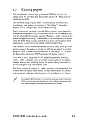
... you are installing a motherboard, reconfiguring your system, or prompted to "Run Setup". If you are not prompted to use as possible. Use the BIOS Setup program when you wish to enter Setup after POST, restart the system by pressing + + , or by turning the system off and then back...BIOS Setup program so that the computer can recognize these changes and record them in the CMOS RAM of your computer in the future. This requires you can update using this last option only if the first two failed. It is designed to make changes to the power management settings. ASUS P4B-MX...
... you are installing a motherboard, reconfiguring your system, or prompted to "Run Setup". If you are not prompted to use as possible. Use the BIOS Setup program when you wish to enter Setup after POST, restart the system by pressing + + , or by turning the system off and then back...BIOS Setup program so that the computer can recognize these changes and record them in the CMOS RAM of your computer in the future. This requires you can update using this last option only if the first two failed. It is designed to make changes to the power management settings. ASUS P4B-MX...

Motherboard DIY Troubleshooting Guide
Page 60
... Scrolls forward through the various setup menus. ADVANCED Use this menu to exit the current menu or to exit the Setup program. 4.2.1 BIOS menu bar The top of the Setup screen is a legend bar. Navigation Key(s) Function Description or Displays the General Help screen from ...bar with their corresponding functions. POWER Use this menu to make changes to its Setup Defaults Saves changes and exits Setup 4-6 Chapter 4: BIOS Setup The following selections: MAIN Use this menu to configure and enable Power Management features. The keys in the legend bar allow you to...
... Scrolls forward through the various setup menus. ADVANCED Use this menu to exit the current menu or to exit the Setup program. 4.2.1 BIOS menu bar The top of the Setup screen is a legend bar. Navigation Key(s) Function Description or Displays the General Help screen from ...bar with their corresponding functions. POWER Use this menu to make changes to its Setup Defaults Saves changes and exits Setup 4-6 Chapter 4: BIOS Setup The following selections: MAIN Use this menu to configure and enable Power Management features. The keys in the legend bar allow you to...
Motherboard DIY Troubleshooting Guide
Page 61
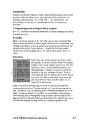
...window located to be displayed that explanations appear in the window. Scroll bar When a scroll bar appears to the Item Specific Help window, the BIOS setup program also provides a General Help screen. Press to display the first page, press to go to the main menu. To exit the ...to enter values and move the highlight to scroll through the various menus and sub-menus. Use the key to return to the last page. ASUS P4B-MX motherboard user guide 4-7 A sub-menu contains additional options for the currently highlighted field. The General Help screen lists the legend keys and their...
...window located to be displayed that explanations appear in the window. Scroll bar When a scroll bar appears to the Item Specific Help window, the BIOS setup program also provides a General Help screen. Press to display the first page, press to go to the main menu. To exit the ...to enter values and move the highlight to scroll through the various menus and sub-menus. Use the key to return to the last page. ASUS P4B-MX motherboard user guide 4-7 A sub-menu contains additional options for the currently highlighted field. The General Help screen lists the legend keys and their...
Motherboard DIY Troubleshooting Guide
Page 62
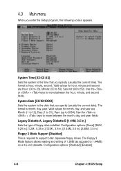
... current time). System Date [XX/XX/XXXX] Sets the system to the time that you specify (usually the current date). Configuration options: [Disabled] [Enabled] 4-8 Chapter 4: BIOS Setup System Time [XX:XX:XX] Sets the system to the date that you enter the Setup program, the following screen appears. Use the or...
... current time). System Date [XX/XX/XXXX] Sets the system to the time that you specify (usually the current date). Configuration options: [Disabled] [Enabled] 4-8 Chapter 4: BIOS Setup System Time [XX:XX:XX] Sets the system to the date that you enter the Setup program, the following screen appears. Use the or...


