Motherboard DIY Troubleshooting Guide
Page 22
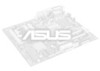
ATX Power Connector 24.4cm (9.6in) 2.2 Motherboard layout PS/2KBMS T: Mouse B: Keyboard Bottom: USB1 USB2 Top: RJ-45 SPDIF 24.4cm (9.60in) Socket 478 CPU_FAN Multi I/O DIMM Socket 1 (... Port (AGP) Realtek RTL8100 AUX_CON Audio Codec CD_IN PCI1 P4B-LX PCI2 PCI3 CR2032 3V Lithium Cell CMOS Power LED1 01 23 1 1 1 Intel I/O Controller Hub (ICH2) CLR_CMOS 2Mbit Firmware Hub BUZZER USB23 PANEL Figure 2-2 Motherboard Layout The audio codec, external and internal audio connectors, and LAN features are grayed out in the above motherboard...
ATX Power Connector 24.4cm (9.6in) 2.2 Motherboard layout PS/2KBMS T: Mouse B: Keyboard Bottom: USB1 USB2 Top: RJ-45 SPDIF 24.4cm (9.60in) Socket 478 CPU_FAN Multi I/O DIMM Socket 1 (... Port (AGP) Realtek RTL8100 AUX_CON Audio Codec CD_IN PCI1 P4B-LX PCI2 PCI3 CR2032 3V Lithium Cell CMOS Power LED1 01 23 1 1 1 Intel I/O Controller Hub (ICH2) CLR_CMOS 2Mbit Firmware Hub BUZZER USB23 PANEL Figure 2-2 Motherboard Layout The audio codec, external and internal audio connectors, and LAN features are grayed out in the above motherboard...
Motherboard DIY Troubleshooting Guide
Page 39
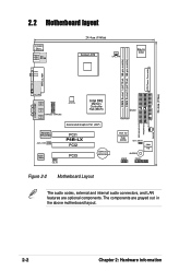
CPU and chassis fan connectors (3-pin CPU_FAN, CHASSIS_FAN) The fan connectors support a CPU fan and a chassis fan at +12V. P4B-LX P4B-LX USB Header Figure 2-24 USB Header USB23 1 5 6 10 1: USB Power 6: USB Power 2: USBP2- 7: USBP3- 3: USBP2+ 8: USBP3+ 4: GND 9: GND 5: NC ASUS P4B-LX motherboard user guide 2-19 ...Orient the fans properly to allow air flow to the ground pin. Lack of the expansion slots. DO NOT place jumper caps on the rear panel are not jumpers! USB header (10-1 pin USB23) If the USB ports on the fan connectors...
CPU and chassis fan connectors (3-pin CPU_FAN, CHASSIS_FAN) The fan connectors support a CPU fan and a chassis fan at +12V. P4B-LX P4B-LX USB Header Figure 2-24 USB Header USB23 1 5 6 10 1: USB Power 6: USB Power 2: USBP2- 7: USBP3- 3: USBP2+ 8: USBP3+ 4: GND 9: GND 5: NC ASUS P4B-LX motherboard user guide 2-19 ...Orient the fans properly to allow air flow to the ground pin. Lack of the expansion slots. DO NOT place jumper caps on the rear panel are not jumpers! USB header (10-1 pin USB23) If the USB ports on the fan connectors...
Motherboard DIY Troubleshooting Guide
Page 42
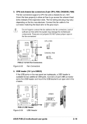
...a fax/modem. The system message LED feature requires an ACPI OS and driver support. 2-22 Chapter 2: Hardware information 8. RESET RESET_G P4B-LX P4B-LX System Panel Connectors PWRBTN IDELED RESETCON PWRLED * Requires an ATX power supply. The LED blinks when data is for this LED is ON, when there ...is no incoming data signal. Figure 2-28 System Panel Connectors • System Power LED Lead (3-1 pin PWRLED) This 3-1 pin connector connects to hear system beeps and warnings. • System Message LED Lead (2-pin SUSLED) This 2-pin...
...a fax/modem. The system message LED feature requires an ACPI OS and driver support. 2-22 Chapter 2: Hardware information 8. RESET RESET_G P4B-LX P4B-LX System Panel Connectors PWRBTN IDELED RESETCON PWRLED * Requires an ATX power supply. The LED blinks when data is for this LED is ON, when there ...is no incoming data signal. Figure 2-28 System Panel Connectors • System Power LED Lead (3-1 pin PWRLED) This 3-1 pin connector connects to hear system beeps and warnings. • System Message LED Lead (2-pin SUSLED) This 2-pin...
Motherboard DIY Troubleshooting Guide
Page 47
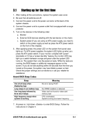
...that all the connections, replace the system case cover. 2. Connect the power cord to enter BIOS Setup. System power (if you need to the power connector at a lower frequency 7. For ATX power supplies, the system LED lights up when you turned on the power, the system may light up or ... loop One long beep followed by three short beeps High frequency beeps when system is equipped with the last device on the system front panel case lights up. ASUS P4B-LX motherboard user guide 3-1 Connect the power cord to switch on the power supply as well as press the ATX power switch on ....
...that all the connections, replace the system case cover. 2. Connect the power cord to enter BIOS Setup. System power (if you need to the power connector at a lower frequency 7. For ATX power supplies, the system LED lights up when you turned on the power, the system may light up or ... loop One long beep followed by three short beeps High frequency beeps when system is equipped with the last device on the system front panel case lights up. ASUS P4B-LX motherboard user guide 3-1 Connect the power cord to switch on the power supply as well as press the ATX power switch on ....
Motherboard DIY Troubleshooting Guide
Page 105
... Boot Up NumLock Status 4-13 Boot Virus Detection 4-29 C Central Processing Unit (CPU) 2-4 CPU socket 1-3 fan connector 2-9 installation 2-5 Level 1/Level 2 Cache 4-16 Speed 4-15 Chip Configuration 4-17 Clear RTC RAM 2-19 Communications and Networking Riser 2-16...panel 2-22 power supply 2-20 primary/secondary IDE 2-18 CPU frequency 2-17 D DIMM installing 2-11 removing 2-12 DIMM sockets 1-3 DIP switches 1-4, 2-16 E E-Color 3Deep 5-4 Expansion card installation 2-13 IRQ assigments 2-14 Expansion slots 1-4, 2-13 AGP 1-4, 2-15 PCI 1-4, 2-15 CNR 2-16 F Flash EEPROM 1-4 Floppy 3 Mode 4-8 ASUS P4B-LX...
... Boot Up NumLock Status 4-13 Boot Virus Detection 4-29 C Central Processing Unit (CPU) 2-4 CPU socket 1-3 fan connector 2-9 installation 2-5 Level 1/Level 2 Cache 4-16 Speed 4-15 Chip Configuration 4-17 Clear RTC RAM 2-19 Communications and Networking Riser 2-16...panel 2-22 power supply 2-20 primary/secondary IDE 2-18 CPU frequency 2-17 D DIMM installing 2-11 removing 2-12 DIMM sockets 1-3 DIP switches 1-4, 2-16 E E-Color 3Deep 5-4 Expansion card installation 2-13 IRQ assigments 2-14 Expansion slots 1-4, 2-13 AGP 1-4, 2-15 PCI 1-4, 2-15 CNR 2-16 F Flash EEPROM 1-4 Floppy 3 Mode 4-8 ASUS P4B-LX...


