Motherboard DIY Troubleshooting Guide
Page 3
... viii How this guide is organized viii Conventions used in this guide ix Where to find more information ix ASUS contact information x Chapter 1: Product introduction 1-1 1.1 Welcome 1-1 1.2 Package contents 1-1 1.3 Overview 1-2 1.3.1 ... 2-1 2.1.2 Screw holes 2-1 2.2 Motherboard layout 2-2 2.3 Before you proceed 2-3 2.4 Central Processing Unit (CPU 2-4 2.4.1 Overview 2-4 2.4.2 Installing the CPU 2-5 2.4.3 Installing the heatsink and fan 2-7 2.4.4 Connecting the CPU fan cable 2-9 2.5 System memory 2-10 2.5.1 Overview 2-10 2.5.2 Memory configurations 2-10 2.5.3 Installing a ...
... viii How this guide is organized viii Conventions used in this guide ix Where to find more information ix ASUS contact information x Chapter 1: Product introduction 1-1 1.1 Welcome 1-1 1.2 Package contents 1-1 1.3 Overview 1-2 1.3.1 ... 2-1 2.1.2 Screw holes 2-1 2.2 Motherboard layout 2-2 2.3 Before you proceed 2-3 2.4 Central Processing Unit (CPU 2-4 2.4.1 Overview 2-4 2.4.2 Installing the CPU 2-5 2.4.3 Installing the heatsink and fan 2-7 2.4.4 Connecting the CPU fan cable 2-9 2.5 System memory 2-10 2.5.1 Overview 2-10 2.5.2 Memory configurations 2-10 2.5.3 Installing a ...
Motherboard DIY Troubleshooting Guide
Page 15
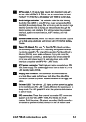
...Intel proprietary Hub interface. The LED goes OFF when the system is slotted to prevent incorrect insertion of the floppy disk cable. 7 Onboard LED. ASUS P4B-LX motherboard user guide 1-3 This socket accommodates the Intel® Pentium® 4 478/Northwood Processor with the south bridge Intel I/O Controller Hub 2...devices. One side of the Intel 845 (Brookdale) chipset. The LED remains ON when the system goes to an ATX 12V power supply. 1 CPU socket. This controller called mPGA478 B. This 20-pin connector connects to sleep mode. The power supply must have at least 1A on the +...
...Intel proprietary Hub interface. The LED goes OFF when the system is slotted to prevent incorrect insertion of the floppy disk cable. 7 Onboard LED. ASUS P4B-LX motherboard user guide 1-3 This socket accommodates the Intel® Pentium® 4 478/Northwood Processor with the south bridge Intel I/O Controller Hub 2...devices. One side of the Intel 845 (Brookdale) chipset. The LED remains ON when the system goes to an ATX 12V power supply. 1 CPU socket. This controller called mPGA478 B. This 20-pin connector connects to sleep mode. The power supply must have at least 1A on the +...
Motherboard DIY Troubleshooting Guide
Page 17
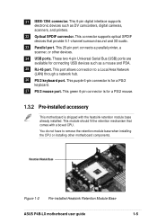
...Local Area Network (LAN) through a network hub. 26 PS/2 keyboard port. Retention Module Base Figure 1-2 Pre-installed Heatsink Retention Module Base ASUS P4B-LX motherboard user guide 1-5 21 IEEE-1394 connector. This 25-pin port connects a parallel printer, a scanner, or other motherboard components. This ...purple 6-pin connector is shipped with a boxed CPU. This 6-pin digital interface supports electronic devices such as a mouse and PDA. 25 RJ-45 port. This port allows connection to remove...
...Local Area Network (LAN) through a network hub. 26 PS/2 keyboard port. Retention Module Base Figure 1-2 Pre-installed Heatsink Retention Module Base ASUS P4B-LX motherboard user guide 1-5 21 IEEE-1394 connector. This 25-pin port connects a parallel printer, a scanner, or other motherboard components. This ...purple 6-pin connector is shipped with a boxed CPU. This 6-pin digital interface supports electronic devices such as a mouse and PDA. 25 RJ-45 port. This port allows connection to remove...
Motherboard DIY Troubleshooting Guide
Page 24
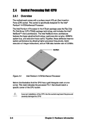
...processor frequencies, faster execution of integer instructions, and an FSB data transfer rate of the CPU into the socket may bend the pins and severely damage the CPU! 2-4 Chapter 2: Hardware information The Intel NetBurst micro-architecture features the hyper-pipelined technology,... rapid execution engine, 400MHz system bus, and execution trace cache. 2.4 Central Processing Unit (CPU) 2.4.1 Overview The motherboard comes with a surface mount 478-pin Zero Insertion Force (ZIF) socket. This socket is specifically designed for...
...processor frequencies, faster execution of integer instructions, and an FSB data transfer rate of the CPU into the socket may bend the pins and severely damage the CPU! 2-4 Chapter 2: Hardware information The Intel NetBurst micro-architecture features the hyper-pipelined technology,... rapid execution engine, 400MHz system bus, and execution trace cache. 2.4 Central Processing Unit (CPU) 2.4.1 Overview The motherboard comes with a surface mount 478-pin Zero Insertion Force (ZIF) socket. This socket is specifically designed for...
Motherboard DIY Troubleshooting Guide
Page 25
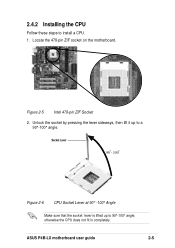
2.4.2 Installing the CPU Follow these steps to a 90°-100° angle. Locate the 478-pin ZIF socket on the motherboard. Unlock the socket by pressing the lever sideways, then lift it up to 90°-100° angle, otherwise the CPU does not fit in completely. Socket Lever 90 - 100 Figure 2-6 CPU Socket Lever at 90° -100° Angle Make sure that the socket lever is lifted up to install a CPU. 1. ASUS P4B-LX motherboard user guide 2-5 Figure 2-5 Intel 478-pin ZIF Socket 2.
2.4.2 Installing the CPU Follow these steps to a 90°-100° angle. Locate the 478-pin ZIF socket on the motherboard. Unlock the socket by pressing the lever sideways, then lift it up to 90°-100° angle, otherwise the CPU does not fit in completely. Socket Lever 90 - 100 Figure 2-6 CPU Socket Lever at 90° -100° Angle Make sure that the socket lever is lifted up to install a CPU. 1. ASUS P4B-LX motherboard user guide 2-5 Figure 2-5 Intel 478-pin ZIF Socket 2.
Motherboard DIY Troubleshooting Guide
Page 26
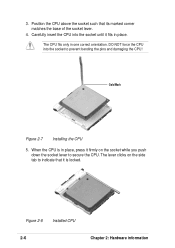
...tab to indicate that its marked corner matches the base of the socket lever. 4. When the CPU is locked. The CPU fits only in place. Gold Mark Figure 2-7 Installing the CPU 5. Figure 2-8 Installed CPU 2-6 Chapter 2: Hardware information The lever clicks on the socket while you push down the socket ...lever to prevent bending the pins and damaging the CPU! Carefully insert the CPU into the socket to secure the CPU. Position the CPU above the socket such that it is in place, press it fits in one correct orientation.
...tab to indicate that its marked corner matches the base of the socket lever. 4. When the CPU is locked. The CPU fits only in place. Gold Mark Figure 2-7 Installing the CPU 5. Figure 2-8 Installed CPU 2-6 Chapter 2: Hardware information The lever clicks on the socket while you push down the socket ...lever to prevent bending the pins and damaging the CPU! Carefully insert the CPU into the socket to secure the CPU. Position the CPU above the socket such that it is in place, press it fits in one correct orientation.
Motherboard DIY Troubleshooting Guide
Page 27
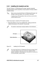
... these steps to ensure optimum thermal condition and performance. Place the heatsink on top of the installed CPU, making sure that you buy a CPU separately, make sure that the heatsink fits properly on the motherboard. ASUS P4B-LX motherboard user guide 2-7 2.4.3 Installing the heatsink and fan The Intel® Pentium® 4 478/Northwood Processor requires...
... these steps to ensure optimum thermal condition and performance. Place the heatsink on top of the installed CPU, making sure that you buy a CPU separately, make sure that the heatsink fits properly on the motherboard. ASUS P4B-LX motherboard user guide 2-7 2.4.3 Installing the heatsink and fan The Intel® Pentium® 4 478/Northwood Processor requires...
Motherboard DIY Troubleshooting Guide
Page 29
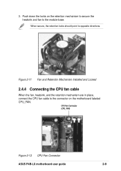
3. CPU Fan Connector (CPU_FAN) Figure 2-12 CPU Fan Connector ASUS P4B-LX motherboard user guide 2-9 Figure 2-11 Fan and Retention Mechanism Installed and Locked 2.4.4 Connecting the CPU fan cable When the fan, heatsink, and the retention mechanism are in place, connect the CPU fan cable to the module base. Push down the locks on the retention mechanism to secure the heatsink and fan to the connector on the motherboard labeled CPU_FAN. When secure, the retention locks should point to opposite directions.
3. CPU Fan Connector (CPU_FAN) Figure 2-12 CPU Fan Connector ASUS P4B-LX motherboard user guide 2-9 Figure 2-11 Fan and Retention Mechanism Installed and Locked 2.4.4 Connecting the CPU fan cable When the fan, heatsink, and the retention mechanism are in place, connect the CPU fan cable to the module base. Push down the locks on the retention mechanism to secure the heatsink and fan to the connector on the motherboard labeled CPU_FAN. When secure, the retention locks should point to opposite directions.
Motherboard DIY Troubleshooting Guide
Page 39
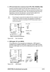
...connectors (3-pin CPU_FAN, CHASSIS_FAN) The fan connectors support a CPU fan and a chassis fan at +12V. Do not...available for two additional USB ports. Lack of the expansion slots. CPU_FAN GND +12V Rotation P4B-LX CHASIS_FAN GND +12V Rotation P4B-LX 12-Volt Fan Connectors Figure 2-23 Fan Connectors 4. Orient the fans properly to allow air...and mount the USB bracket to the ground pin. P4B-LX P4B-LX USB Header Figure 2-24 USB Header USB23 1 5 6 10 1: USB Power 6: USB Power 2: USBP2- 7: USBP3- 3: USBP2+ 8: USBP3+ 4: GND 9: GND 5: NC ASUS P4B-LX motherboard user guide 2-19
...connectors (3-pin CPU_FAN, CHASSIS_FAN) The fan connectors support a CPU fan and a chassis fan at +12V. Do not...available for two additional USB ports. Lack of the expansion slots. CPU_FAN GND +12V Rotation P4B-LX CHASIS_FAN GND +12V Rotation P4B-LX 12-Volt Fan Connectors Figure 2-23 Fan Connectors 4. Orient the fans properly to allow air...and mount the USB bracket to the ground pin. P4B-LX P4B-LX USB Header Figure 2-24 USB Header USB23 1 5 6 10 1: USB Power 6: USB Power 2: USBP2- 7: USBP3- 3: USBP2+ 8: USBP3+ 4: GND 9: GND 5: NC ASUS P4B-LX motherboard user guide 2-19
Motherboard DIY Troubleshooting Guide
Page 40
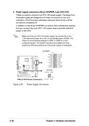
...PWR_OK COM +5.0VDC COM +5.0VDC COM +3.3VDC +3.3VDC ATX12V +12V DC COM +5.0VDC +5.0VDC -5.0VDC COM COM COM PS_ON# COM -12.0VDC +3.3VDC Pin 1 P4B-LX ATX Power Connectors +12V DC COM Figure 2-25 Power Supply Connectors 2-20 Chapter 2: Hardware information The minimum recommended wattage is inadequate. 5. Find the proper orientation... plug to provide sufficient power to fit these connectors in only one orientation. The plugs from the power supply are designed to the CPU. Power supply connectors (20-pin ATXPWR, 4-pin ATX+12V) These connectors connect to an ATX 12V power supply.
...PWR_OK COM +5.0VDC COM +5.0VDC COM +3.3VDC +3.3VDC ATX12V +12V DC COM +5.0VDC +5.0VDC -5.0VDC COM COM COM PS_ON# COM -12.0VDC +3.3VDC Pin 1 P4B-LX ATX Power Connectors +12V DC COM Figure 2-25 Power Supply Connectors 2-20 Chapter 2: Hardware information The minimum recommended wattage is inadequate. 5. Find the proper orientation... plug to provide sufficient power to fit these connectors in only one orientation. The plugs from the power supply are designed to the CPU. Power supply connectors (20-pin ATXPWR, 4-pin ATX+12V) These connectors connect to an ATX 12V power supply.
Motherboard DIY Troubleshooting Guide
Page 47
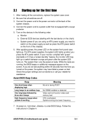
... switch. Be sure that is working Meaning No error during POST No DRAM installed or detected Video card not found or video card memory bad CPU overheated; System running , the BIOS beeps or additional messages appear on the front of the system chassis. 4. After applying power, the power LED on ... light up or switch between orange and green after the system LED turns on. 3.1 Starting up for assistance. External SCSI devices (starting with a surge protector. 5. ASUS P4B-LX motherboard user guide 3-1 After making all switches are running at the back of the chassis). 6.
... switch. Be sure that is working Meaning No error during POST No DRAM installed or detected Video card not found or video card memory bad CPU overheated; System running , the BIOS beeps or additional messages appear on the front of the system chassis. 4. After applying power, the power LED on ... light up or switch between orange and green after the system LED turns on. 3.1 Starting up for assistance. External SCSI devices (starting with a surge protector. 5. ASUS P4B-LX motherboard user guide 3-1 After making all switches are running at the back of the chassis). 6.
Motherboard DIY Troubleshooting Guide
Page 65
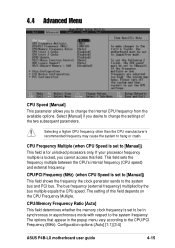
... frequency the clock generator sends to the system bus and PCI bus. Configuration options: [Auto] [1:1] [3:4] ASUS P4B-LX motherboard user guide 4-15 Select [Manual] if you desire to change the internal CPU frequency from the available options. 4.4 Advanced Menu CPU Speed [Manual] This parameter allows you to change the settings of this field. Selecting a higher...
... frequency the clock generator sends to the system bus and PCI bus. Configuration options: [Auto] [1:1] [3:4] ASUS P4B-LX motherboard user guide 4-15 Select [Manual] if you desire to change the internal CPU frequency from the available options. 4.4 Advanced Menu CPU Speed [Manual] This parameter allows you to change the settings of this field. Selecting a higher...
Motherboard DIY Troubleshooting Guide
Page 66
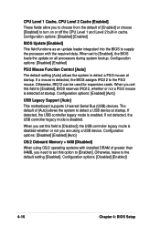
Otherwise, leave to the PS/2 mouse. CPU Level 1 Cache, CPU Level 2 Cache [Enabled] These fields allow you to choose from the default of [Auto] allows the system to detect a USB device at startup. Configuration options: [...Disabled] [Enabled] PS/2 Mouse Function Control [Auto] The default setting [Auto] allows the system to [Enabled], the BIOS loads the update on or off the CPU Level 1 and Level 2 built-in cache. Otherwise, IRQ12 can be used for expansion cards. Configuration options: [Enabled] [Auto] USB Legacy Support [Auto] This motherboard supports...
Otherwise, leave to the PS/2 mouse. CPU Level 1 Cache, CPU Level 2 Cache [Enabled] These fields allow you to choose from the default of [Auto] allows the system to detect a USB device at startup. Configuration options: [...Disabled] [Enabled] PS/2 Mouse Function Control [Auto] The default setting [Auto] allows the system to [Enabled], the BIOS loads the update on or off the CPU Level 1 and Level 2 built-in cache. Otherwise, IRQ12 can be used for expansion cards. Configuration options: [Enabled] [Auto] USB Legacy Support [Auto] This motherboard supports...
Motherboard DIY Troubleshooting Guide
Page 69
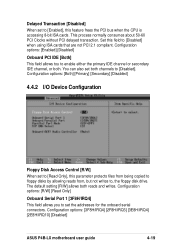
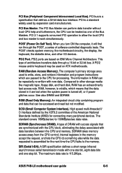
... IDE channel or secondary IDE channel, or both reads and writes. The default setting [R/W] allows both . Set this feature frees the PCI bus when the CPU is accessing 8-bit ISA cards. You can also set the addresses for the onboard serial connectors. This process normally consumes about 50-60 PCI Clocks... being copied to floppy disks by allowing reads from, but not writes to [Disabled]. Configuration options: [3F8H/IRQ4] [2F8H/IRQ3] [3E8H/IRQ4] [2E8H/IRQ10] [Disabled] ASUS P4B-LX motherboard user guide 4-19
... IDE channel or secondary IDE channel, or both reads and writes. The default setting [R/W] allows both . Set this feature frees the PCI bus when the CPU is accessing 8-bit ISA cards. You can also set the addresses for the onboard serial connectors. This process normally consumes about 50-60 PCI Clocks... being copied to floppy disks by allowing reads from, but not writes to [Disabled]. Configuration options: [3F8H/IRQ4] [2F8H/IRQ3] [3E8H/IRQ4] [2E8H/IRQ10] [Disabled] ASUS P4B-LX motherboard user guide 4-19
Motherboard DIY Troubleshooting Guide
Page 77
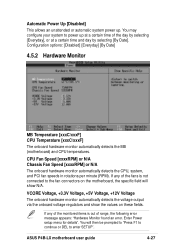
...The onboard hardware monitor automatically detects the CPU, system, and PCI fan speeds in rotations per minute (RPM). You will then be prompted to "Press F1 to continue or DEL to the fan connectors on these fields. ASUS P4B-LX motherboard user guide 4-27 If any of...]. Configuration options: [Disabled] [Everyday] [By Date] 4.5.2 Hardware Monitor MB Temperature [xxxC/xxxF] CPU Temperature [xxxC/xxxF] The onboard hardware monitor automatically detects the MB (motherboard) and CPU temperatures. If any of the monitored items is not connected to enter SETUP". VCORE Voltage, +3.3V ...
...The onboard hardware monitor automatically detects the CPU, system, and PCI fan speeds in rotations per minute (RPM). You will then be prompted to "Press F1 to continue or DEL to the fan connectors on these fields. ASUS P4B-LX motherboard user guide 4-27 If any of...]. Configuration options: [Disabled] [Everyday] [By Date] 4.5.2 Hardware Monitor MB Temperature [xxxC/xxxF] CPU Temperature [xxxC/xxxF] The onboard hardware monitor automatically detects the MB (motherboard) and CPU temperatures. If any of the monitored items is not connected to enter SETUP". VCORE Voltage, +3.3V ...
Motherboard DIY Troubleshooting Guide
Page 88
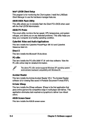
...virus software. The Acrobat Reader software is the first application that gives online gamers the competitive edge in Portable Document Format (PDF). ASUS BIOS Flash Utility This utility allows you keep your computer at a healthy operating condition. E-Color 3Deep This item installs the 3Deep software.... 3Deep is for viewing files saved in multi-player skirmishes. ASUS PC Probe This smart utility monitors the fan speed, CPU temperature, and system voltages, and alerts you on any detected problems. This utility helps you to remotely ...
...virus software. The Acrobat Reader software is the first application that gives online gamers the competitive edge in Portable Document Format (PDF). ASUS BIOS Flash Utility This utility allows you keep your computer at a healthy operating condition. E-Color 3Deep This item installs the 3Deep software.... 3Deep is for viewing files saved in multi-player skirmishes. ASUS PC Probe This smart utility monitors the fan speed, CPU temperature, and system voltages, and alerts you on any detected problems. This utility helps you to remotely ...
Motherboard DIY Troubleshooting Guide
Page 98
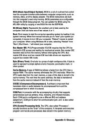
...it into system memory. A byte is configured to restart your computer. CODEC (Compressor/Decompressor). Each COM port is used by the computer. The CPU, also called a serial port. Boot means to support bus master IDE mode. Byte (Binary Term). COM Port. A connector with the accompanying...| Shut Down..." Bus master IDE transfers data to represent a single alphanumeric character, punctuation mark, or other symbol. The cache memory eliminates the CPU wait state. Represents the smallest unit of data used to /from the main memory, a copy of this data is stored in which it ...
...it into system memory. A byte is configured to restart your computer. CODEC (Compressor/Decompressor). Each COM port is used by the computer. The CPU, also called a serial port. Boot means to support bus master IDE mode. Byte (Binary Term). COM Port. A connector with the accompanying...| Shut Down..." Bus master IDE transfers data to represent a single alphanumeric character, punctuation mark, or other symbol. The cache memory eliminates the CPU wait state. Represents the smallest unit of data used to /from the main memory, a copy of this data is stored in which it ...
Motherboard DIY Troubleshooting Guide
Page 101
... that the data stored in the memory accept the request, and lets the CPU do something else while the data requested is volatile, which are lost when the system power is a standard widely used on IBM Micro Channel Architecture. ASUS P4B-LX motherboard user guide G-5 SCSI (Small Computer System Interface). A type of DRAM with...
... that the data stored in the memory accept the request, and lets the CPU do something else while the data requested is volatile, which are lost when the system power is a standard widely used on IBM Micro Channel Architecture. ASUS P4B-LX motherboard user guide G-5 SCSI (Small Computer System Interface). A type of DRAM with...
Motherboard DIY Troubleshooting Guide
Page 105
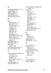
... 3-1 BIOS Flash Utility 5-4 Boot Device Selection 4-28 Boot Up NumLock Status 4-13 Boot Virus Detection 4-29 C Central Processing Unit (CPU) 2-4 CPU socket 1-3 fan connector 2-9 installation 2-5 Level 1/Level 2 Cache 4-16 Speed 4-15 Chip Configuration 4-17 Clear RTC RAM 2-19 Communications...IDE 2-18 CPU frequency 2-17 D DIMM installing 2-11 removing 2-12 DIMM sockets 1-3 DIP switches 1-4, 2-16 E E-Color 3Deep 5-4 Expansion card installation 2-13 IRQ assigments 2-14 Expansion slots 1-4, 2-13 AGP 1-4, 2-15 PCI 1-4, 2-15 CNR 2-16 F Flash EEPROM 1-4 Floppy 3 Mode 4-8 ASUS P4B-LX motherboard user ...
... 3-1 BIOS Flash Utility 5-4 Boot Device Selection 4-28 Boot Up NumLock Status 4-13 Boot Virus Detection 4-29 C Central Processing Unit (CPU) 2-4 CPU socket 1-3 fan connector 2-9 installation 2-5 Level 1/Level 2 Cache 4-16 Speed 4-15 Chip Configuration 4-17 Clear RTC RAM 2-19 Communications...IDE 2-18 CPU frequency 2-17 D DIMM installing 2-11 removing 2-12 DIMM sockets 1-3 DIP switches 1-4, 2-16 E E-Color 3Deep 5-4 Expansion card installation 2-13 IRQ assigments 2-14 Expansion slots 1-4, 2-13 AGP 1-4, 2-15 PCI 1-4, 2-15 CNR 2-16 F Flash EEPROM 1-4 Floppy 3 Mode 4-8 ASUS P4B-LX motherboard user ...


