
P4B-FX User Manual
Page 43
... IR_CN) This connector supports an optional wireless transmitting and receiving infrared module. Use the five pins as shown in Back View and connect a ribbon cable from the module to the motherboard SIR connector according to an open slot in BIOS to a small opening on the rear... panel are inadequate, a USB header is available for use with IR. This module mounts to set to the USB header and mount the USB bracket to the pin definitions. IR_CN 1 Front View Back View +5V IRRX GND IRTX P4B-FX P4B-FX Infrared Module Connector Figure 2-30 Infrared Module Connector ASUS P4B-FX ...
... IR_CN) This connector supports an optional wireless transmitting and receiving infrared module. Use the five pins as shown in Back View and connect a ribbon cable from the module to the motherboard SIR connector according to an open slot in BIOS to a small opening on the rear... panel are inadequate, a USB header is available for use with IR. This module mounts to set to the USB header and mount the USB bracket to the pin definitions. IR_CN 1 Front View Back View +5V IRRX GND IRTX P4B-FX P4B-FX Infrared Module Connector Figure 2-30 Infrared Module Connector ASUS P4B-FX ...

P4B-FX User Manual
Page 45
... Right ASUS P4B-FX motherboard user guide 2-25 CD1 (Black) AUX (White) Left Audio Channel Ground Right Audio Channel P4B-FX P4B-FX Internal Audio Connectors Figure 2-32 Internal Audio Connectors 9. If your chassis has this audio module, you to the front panel connector. 8. Headphone true-level line out connector (3-pin HPHONE) (on audio models only) This connector connects...
... Right ASUS P4B-FX motherboard user guide 2-25 CD1 (Black) AUX (White) Left Audio Channel Ground Right Audio Channel P4B-FX P4B-FX Internal Audio Connectors Figure 2-32 Internal Audio Connectors 9. If your chassis has this audio module, you to the front panel connector. 8. Headphone true-level line out connector (3-pin HPHONE) (on audio models only) This connector connects...
P4B-FX User Manual
Page 46
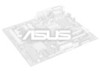
...a time. If your chassis has this lead to the front panel connector . MIC2 1 P4B-FX P4B-FX Internal Microphone Connector Figure 2-34 Internal Microphone Connector 11. CHASSIS 1 +5Volt (Power Supply Stand By) Chassis Signal Ground P4B-FX P4B-FX Chassis Alarm Lead Figure 2-35 Chassis Alarm Lead 2-26 Chapter 2:..." and "Ground" to an optional front panel audio module using a 3-pin audio cable. Chassis alarm lead (4-1 pin CHASSIS) This lead is another microphone connected to the Microphone (pink) jack on audio models only) This connector connects to close the circuit. MIC Power MIC ...
...a time. If your chassis has this lead to the front panel connector . MIC2 1 P4B-FX P4B-FX Internal Microphone Connector Figure 2-34 Internal Microphone Connector 11. CHASSIS 1 +5Volt (Power Supply Stand By) Chassis Signal Ground P4B-FX P4B-FX Chassis Alarm Lead Figure 2-35 Chassis Alarm Lead 2-26 Chapter 2:..." and "Ground" to an optional front panel audio module using a 3-pin audio cable. Chassis alarm lead (4-1 pin CHASSIS) This lead is another microphone connected to the Microphone (pink) jack on audio models only) This connector connects to close the circuit. MIC Power MIC ...
P4B-FX User Manual
Page 47
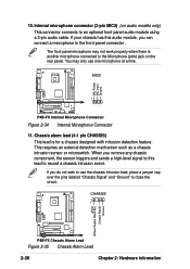
... Keyboard Lock Speaker Power LED Connector PLED+ PLEDKeylock Ground +5V Ground Ground Speaker MLED+ MLEDExtSMI# Ground PWR GND Reset Ground P4B-FX P4B-FX System Panel Connectors Message LED SMI Lead Reset SW ATX Power Switch* * Requires an ATX power supply. The normal status for the ... and blinks when the system is in sleep mode. • Keyboard Lock Lead (1-pin KEYLOCK) This lead connects to a chassis-mounted switch to the system power LED. ASUS P4B-FX motherboard user guide 2-27 12. System panel connectors (20-pin PANEL) This connector accommodates several system front...
... Keyboard Lock Speaker Power LED Connector PLED+ PLEDKeylock Ground +5V Ground Ground Speaker MLED+ MLEDExtSMI# Ground PWR GND Reset Ground P4B-FX P4B-FX System Panel Connectors Message LED SMI Lead Reset SW ATX Power Switch* * Requires an ATX power supply. The normal status for the ... and blinks when the system is in sleep mode. • Keyboard Lock Lead (1-pin KEYLOCK) This lead connects to a chassis-mounted switch to the system power LED. ASUS P4B-FX motherboard user guide 2-27 12. System panel connectors (20-pin PANEL) This connector accommodates several system front...
P4B-FX User Manual
Page 51
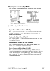
... applying power, the power LED on the screen. If your retailer for the first time 1. While the tests are off. 3. Check the jumper settings and connections or call your monitor complies with "green" standards or if it has a "power standby" feature, the monitor LED may have failed a power-on the chain... LED turns on , hold down to the power connector at a lower frequency 7. System running , the BIOS beeps or additional messages appear on the system front panel case lights up. Follow the instructions in the following order: a. ASUS P4B-FX motherboard user guide 3-1
... applying power, the power LED on the screen. If your retailer for the first time 1. While the tests are off. 3. Check the jumper settings and connections or call your monitor complies with "green" standards or if it has a "power standby" feature, the monitor LED may have failed a power-on the chain... LED turns on , hold down to the power connector at a lower frequency 7. System running , the BIOS beeps or additional messages appear on the system front panel case lights up. Follow the instructions in the following order: a. ASUS P4B-FX motherboard user guide 3-1
