User Manual
Page 4
... 2 utility 4-8 4.1.5 ASUS Update utility 4-9 4.2 BIOS setup program 4-12 4.2.1 BIOS menu screen 4-13 4.2.2 Menu bar 4-13 4.2.3 Navigation keys 4-13 4.2.4 Menu items 4-14 4.2.5 Submenu items 4-14 4.2.6 Configuration fields 4-14 4.2.7 Pop-up window 4-14 4.2.8 Scroll bar 4-14 4.2.9 General help 4-14 4.3 Main menu 4-15 4.3.1 System Time 4-15 4.3.2 System Date 4-15 4.3.3 SATA 1/2 4-16 4.3.4 Storage Configuration 4-17 4.3.5 System Information 4-18 4.4 Advanced menu 4-19 4.4.1 CPU Configuration 4-19...
... 2 utility 4-8 4.1.5 ASUS Update utility 4-9 4.2 BIOS setup program 4-12 4.2.1 BIOS menu screen 4-13 4.2.2 Menu bar 4-13 4.2.3 Navigation keys 4-13 4.2.4 Menu items 4-14 4.2.5 Submenu items 4-14 4.2.6 Configuration fields 4-14 4.2.7 Pop-up window 4-14 4.2.8 Scroll bar 4-14 4.2.9 General help 4-14 4.3 Main menu 4-15 4.3.1 System Time 4-15 4.3.2 System Date 4-15 4.3.3 SATA 1/2 4-16 4.3.4 Storage Configuration 4-17 4.3.5 System Information 4-18 4.4 Advanced menu 4-19 4.4.1 CPU Configuration 4-19...
User Manual
Page 8
... This chapter gives a general description of ASUS P2-P5G41/P4-P5G41. Chapter 3: Motherboard information This chapter gives information about the ASUS P2-P5G41/P4-P5G41 barebone system. This chapter includes the motherboard layout, jumper settings, and connector locations. 4. Lithium-Ion Battery Warning CAUTION: Danger of explosion if battery is organized This guide contains the following parts: 1. LASER PRODUCT WARNING CLASS 1 LASER PRODUCT About this guide is incorrectly replaced.
... This chapter gives a general description of ASUS P2-P5G41/P4-P5G41. Chapter 3: Motherboard information This chapter gives information about the ASUS P2-P5G41/P4-P5G41 barebone system. This chapter includes the motherboard layout, jumper settings, and connector locations. 4. Lithium-Ion Battery Warning CAUTION: Danger of explosion if battery is organized This guide contains the following parts: 1. LASER PRODUCT WARNING CLASS 1 LASER PRODUCT About this guide is incorrectly replaced.
User Manual
Page 12
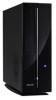
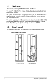
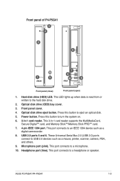
...supports up to 8GB system memory using unbuffered non-ECC DDR2 800/667MHz DIMMs, high-resolution graphics via integrated graphics controller, Serial ATA, USB 2.0, and eight-channel high-definition audio CODEC. 1.2 Front panel The illustrations below show the front panels of P2-P5G41 1 2 3 4 5 6 7 8 10 9 Front panel (close) Front panel (open) 1-2 Chapter 1: System introduction The ASUS...you for purchasing the ASUS P2-P5G41/P4-P5G41! Front panel of the P2-P5G41 and P4-P5G41. The system comes in a stylish casing and powered by an ASUS motherboard that supports the Intel® ...
...supports up to 8GB system memory using unbuffered non-ECC DDR2 800/667MHz DIMMs, high-resolution graphics via integrated graphics controller, Serial ATA, USB 2.0, and eight-channel high-definition audio CODEC. 1.2 Front panel The illustrations below show the front panels of P2-P5G41 1 2 3 4 5 6 7 8 10 9 Front panel (close) Front panel (open) 1-2 Chapter 1: System introduction The ASUS...you for purchasing the ASUS P2-P5G41/P4-P5G41! Front panel of the P2-P5G41 and P4-P5G41. The system comes in a stylish casing and powered by an ASUS motherboard that supports the Intel® ...
User Manual
Page 13
.... 5. Press this button to turn the system on. 6. 3-in -1 card reader supports the MultiMediaCard, Secure Digital™ card, and Memory Stick™/Memory Stick PRO™ card. 7. 4-pin IEEE 1394 port. This 3-in -1 card reader. Headphone port (lime). Hard disk drive (HDD) LED. Optical disk drive eject button. Power button. ASUS P2-P5G41/P4-P5G41 1-3 This LED lights up when data is read from or written to an...
.... 5. Press this button to turn the system on. 6. 3-in -1 card reader supports the MultiMediaCard, Secure Digital™ card, and Memory Stick™/Memory Stick PRO™ card. 7. 4-pin IEEE 1394 port. This 3-in -1 card reader. Headphone port (lime). Hard disk drive (HDD) LED. Optical disk drive eject button. Power button. ASUS P2-P5G41/P4-P5G41 1-3 This LED lights up when data is read from or written to an...
User Manual
Page 15
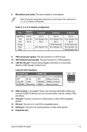
...LAN port LED indications ACT/LINK LED Status Description OFF No link YELLOW Linked BLINKING Data activity SPEED LED Status Description OFF 10Mbps connection ORANGE 100Mbps connection GREEN 1Gbps connection ACT/LINK SPEED LED LED LAN port... serial devices. 16. This port connects to USB 2.0 devices such as a mouse, printer, scanner, camera, PDA, and others. 13. VGA port. Audio 2, 4, 6, or 8-channel configuration Port Light Blue Lime Pink Orange Black Gray Headset 2-channel...the function of the audio ports in 2, 4, 6, or 8-channel configuration. ASUS P2-P5G41/P4-P5G41 1-5
...LAN port LED indications ACT/LINK LED Status Description OFF No link YELLOW Linked BLINKING Data activity SPEED LED Status Description OFF 10Mbps connection ORANGE 100Mbps connection GREEN 1Gbps connection ACT/LINK SPEED LED LED LAN port... serial devices. 16. This port connects to USB 2.0 devices such as a mouse, printer, scanner, camera, PDA, and others. 13. VGA port. Audio 2, 4, 6, or 8-channel configuration Port Light Blue Lime Pink Orange Black Gray Headset 2-channel...the function of the audio ports in 2, 4, 6, or 8-channel configuration. ASUS P2-P5G41/P4-P5G41 1-5
User Manual
Page 16
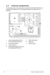
LGA775 socket 1-6 Chapter 1: System introduction PCIE raiser bracket (connected to the motherboard PCIe slot) 5. ASUS motherboard 6. Power supply unit 4. DIMM slots 7. Front panel assembly 3. The installed components are labeled for your reference. 3 1 2 4 7 5 6 1. 5.25 inch optical disk drive and 3.5 inch hard disk drive cage 2. 1.4 Internal components The illustration below is the internal view of the ASUS P2-P5G41/P4-P5G41 when you remove the chassis cover.
LGA775 socket 1-6 Chapter 1: System introduction PCIE raiser bracket (connected to the motherboard PCIe slot) 5. ASUS motherboard 6. Power supply unit 4. DIMM slots 7. Front panel assembly 3. The installed components are labeled for your reference. 3 1 2 4 7 5 6 1. 5.25 inch optical disk drive and 3.5 inch hard disk drive cage 2. 1.4 Internal components The illustration below is the internal view of the ASUS P2-P5G41/P4-P5G41 when you remove the chassis cover.
User Manual
Page 18
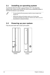
... corresponding updates to maximize the features of your system Press the power button ( ) to your OS documentation for detailed information. 2.2 Powering up P2-P5G41 P4-P5G41 2-2 Chapter 2: Starting up your hardware. • To ensure that the OS work properly, install the drivers included in this chapter for reference only. Use the setup procedures presented in the Support CD. • Motherboard settings and...
... corresponding updates to maximize the features of your system Press the power button ( ) to your OS documentation for detailed information. 2.2 Powering up P2-P5G41 P4-P5G41 2-2 Chapter 2: Starting up your hardware. • To ensure that the OS work properly, install the drivers included in this chapter for reference only. Use the setup procedures presented in the Support CD. • Motherboard settings and...
User Manual
Page 21
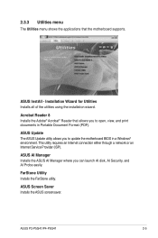
... you to update the motherboard BIOS in Portable Document Format (PDF). ASUS InstAll - Acrobat Reader 8 Installs the Adobe® Acrobat® Reader that the motherboard supports. ASUS P2-P5G41/P4-P5G41 2-5 ASUS Update The ASUS Update utility allows you to open, view, and print documents in a Windows® environment. FarStone Utility Installs the FarStone utility. Installation Wizard for Utilities Installs all of the utilities using the installation wizard. ASUS Screen Saver Installs the ASUS screensaver...
... you to update the motherboard BIOS in Portable Document Format (PDF). ASUS InstAll - Acrobat Reader 8 Installs the Adobe® Acrobat® Reader that the motherboard supports. ASUS P2-P5G41/P4-P5G41 2-5 ASUS Update The ASUS Update utility allows you to open, view, and print documents in a Windows® environment. FarStone Utility Installs the FarStone utility. Installation Wizard for Utilities Installs all of the utilities using the installation wizard. ASUS Screen Saver Installs the ASUS screensaver...
User Manual
Page 32
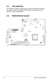
... DDR2 DIMM_A1 (64bit, 240-pin module) DDR2 DIMM_B1 (64bit, 240-pin module) SPDIF_OUT SPDIF_OUT1 33cm(13in) Intel® ICH7 LED_CON PWR_FAN Super I/O RTM 870T-954 VIA VT6325 CR_SOCKET CPU_FAN LGA775 ATX12V USBPW56 RSTSW PWRSW E1394 USB56 FRONT_ AUD VGA DVI 22.4cm(8.8in) 3-2 Chapter 3: Motherboard info 3.1 Introduction The P2-P5G41/P4-P5G41 barebone system comes with an ASUS motherboard.
... DDR2 DIMM_A1 (64bit, 240-pin module) DDR2 DIMM_B1 (64bit, 240-pin module) SPDIF_OUT SPDIF_OUT1 33cm(13in) Intel® ICH7 LED_CON PWR_FAN Super I/O RTM 870T-954 VIA VT6325 CR_SOCKET CPU_FAN LGA775 ATX12V USBPW56 RSTSW PWRSW E1394 USB56 FRONT_ AUD VGA DVI 22.4cm(8.8in) 3-2 Chapter 3: Motherboard info 3.1 Introduction The P2-P5G41/P4-P5G41 barebone system comes with an ASUS motherboard.
User Manual
Page 37
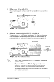
...P5Q8L PIN 1 P5Q8L LED Connector 6. The plugs from the power supply are for ATX power supply plugs. otherwise, the system will not boot. • We recommend that your power supply unit (PSU) can provide at least the minimum power required by your system. ASUS P2-P5G41/P4-P5G41 3-7 Find the proper... GND PSON# GND GND GND -5 Volts +5 Volts +5 Volts +5 Volts GND P5Q8L P5Q8L ATX Power Connectors • DO NOT forget to fit these connectors in the system front panel. LED connector (6-1 pin LED_CON) This connector supports the Power and HDD activity LEDs in only one orientation.
...P5Q8L PIN 1 P5Q8L LED Connector 6. The plugs from the power supply are for ATX power supply plugs. otherwise, the system will not boot. • We recommend that your power supply unit (PSU) can provide at least the minimum power required by your system. ASUS P2-P5G41/P4-P5G41 3-7 Find the proper... GND PSON# GND GND GND -5 Volts +5 Volts +5 Volts +5 Volts GND P5Q8L P5Q8L ATX Power Connectors • DO NOT forget to fit these connectors in the system front panel. LED connector (6-1 pin LED_CON) This connector supports the Power and HDD activity LEDs in only one orientation.
User Manual
Page 42
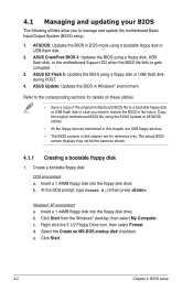
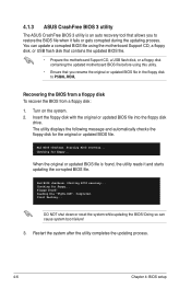
... of the original motherboard BIOS file to a bootable floppy disk or USB flash disk in Windows® environment. ASUS Update: Updates the BIOS in case you to the corresponding sections for reference only. The actual BIOS screen displays may not be the same as shown. 4.1.1 Creating a bootable floppy disk 1. Refer to manage and update the motherboard Basic Input/Output System (BIOS) setup. 1. Create a bootable...
... of the original motherboard BIOS file to a bootable floppy disk or USB flash disk in Windows® environment. ASUS Update: Updates the BIOS in case you to the corresponding sections for reference only. The actual BIOS screen displays may not be the same as shown. 4.1.1 Creating a bootable floppy disk 1. Refer to manage and update the motherboard Basic Input/Output System (BIOS) setup. 1. Create a bootable...
User Manual
Page 46
... system boot failure! 3. Insert the floppy disk with the original or updated BIOS file into the floppy disk drive. Completed. DO NOT shut down or reset the system while updating the BIOS! Starting BIOS recovery... Doing so can update a corrupted BIOS file using the motherboard Support CD, a floppy disk, or USB flash disk that contains the updated BIOS file. • Prepare the motherboard Support CD, a USB flash...
... system boot failure! 3. Insert the floppy disk with the original or updated BIOS file into the floppy disk drive. Completed. DO NOT shut down or reset the system while updating the BIOS! Starting BIOS recovery... Doing so can update a corrupted BIOS file using the motherboard Support CD, a floppy disk, or USB flash disk that contains the updated BIOS file. • Prepare the motherboard Support CD, a USB flash...
User Manual
Page 48
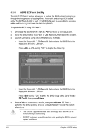
... boot failure! 4-8 Chapter 4: BIOS setup Download the latest BIOS file from a floppy disk and using EZ Flash 2: 1. EZ Flash 2 performs the BIOS updating process and automatically reboots the system when done. • This function supports USB ...BOARD: P5Q8L P-P5G41 VER: 0209 (H:02 B:09) DATE: 02/09/2009 Update ROM BOARD: Unknown VER: Unknown DATE: Unknown PATH: A:\ A: Note [Enter] Select or Load [Tab] Switch [Up/Down/Home/End] Move [B] Backup [V] Drive Info [ESC] Exit • Insert the floppy disk / USB flash disk that contains the BIOS file to the floppy disk drive or a USB...
... boot failure! 4-8 Chapter 4: BIOS setup Download the latest BIOS file from a floppy disk and using EZ Flash 2: 1. EZ Flash 2 performs the BIOS updating process and automatically reboots the system when done. • This function supports USB ...BOARD: P5Q8L P-P5G41 VER: 0209 (H:02 B:09) DATE: 02/09/2009 Update ROM BOARD: Unknown VER: Unknown DATE: Unknown PATH: A:\ A: Note [Enter] Select or Load [Tab] Switch [Up/Down/Home/End] Move [B] Backup [V] Drive Info [ESC] Exit • Insert the floppy disk / USB flash disk that contains the BIOS file to the floppy disk drive or a USB...
User Manual
Page 49
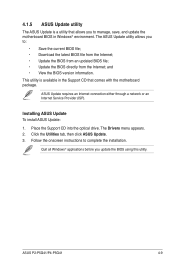
... drive. Quit all Windows® applications before you to: • Save the current BIOS file; • Download the latest BIOS file from the Internet; • Update the BIOS from an updated BIOS file; • Update the BIOS directly from the Internet; The Drivers menu appears. 2. Click the Utilities tab, then click ASUS Update. 3. ASUS P2-P5G41/P4-P5G41 4-9 This utility is a utility that comes with the motherboard package. The ASUS Update...
... drive. Quit all Windows® applications before you to: • Save the current BIOS file; • Download the latest BIOS file from the Internet; • Update the BIOS from an updated BIOS file; • Update the BIOS directly from the Internet; The Drivers menu appears. 2. Click the Utilities tab, then click ASUS Update. 3. ASUS P2-P5G41/P4-P5G41 4-9 This utility is a utility that comes with the motherboard package. The ASUS Update...
User Manual
Page 52
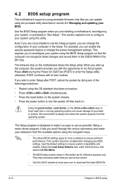
... from the available options using the navigation keys. • The default BIOS settings apply for reference purposes only. 4.2 BIOS setup program This motherboard supports a programmable firmware chip that the computer can recognize these changes and record them in the...Setup program is designed to use the Setup program, you can change the power management settings. Being a menu-driven program, it lets you are installing a motherboard, reconfiguring your system using the provided utility described in section 4.1 Managing and updating your data or system. Use the BIOS Setup...
... from the available options using the navigation keys. • The default BIOS settings apply for reference purposes only. 4.2 BIOS setup program This motherboard supports a programmable firmware chip that the computer can recognize these changes and record them in the...Setup program is designed to use the Setup program, you can change the power management settings. Being a menu-driven program, it lets you are installing a motherboard, reconfiguring your system using the provided utility described in section 4.1 Managing and updating your data or system. Use the BIOS Setup...
User Manual
Page 59
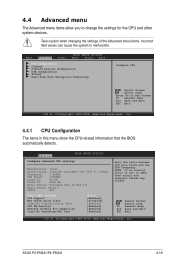
... items in CMOS then actual and setpoint values may differ. Main Advanced Power BIOS SETUP UTILITY Boot Tools Exit CPU Configuration Chipset Onboard Devices Configuration USB Configuration PCIPnP Real-Time Disk Encryption Technology Configure CPU. Advanced BIOS SETUP UTILITY Configure advanced CPU settings Manufacturer: Intel Brand String: Intel(R) Core(TM)2 CPU 6300 @ 1.86GHz Frequency: 1.86GHz FSB Speed: 1066MHz Cache L1: 64 KB Cache L2: 2048 KB Ratio...
... items in CMOS then actual and setpoint values may differ. Main Advanced Power BIOS SETUP UTILITY Boot Tools Exit CPU Configuration Chipset Onboard Devices Configuration USB Configuration PCIPnP Real-Time Disk Encryption Technology Configure CPU. Advanced BIOS SETUP UTILITY Configure advanced CPU settings Manufacturer: Intel Brand String: Intel(R) Core(TM)2 CPU 6300 @ 1.86GHz Frequency: 1.86GHz FSB Speed: 1066MHz Cache L1: 64 KB Cache L2: 2048 KB Ratio...
User Manual
Page 60
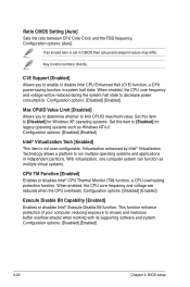
... frequency and voltage are reduced when the CPU overheats. Configuration options: [Disabled] [Enabled] 4-20 Chapter 4: BIOS setup Key in CMOS then actual and setpoint values may differ. Virtualization enhanced by Intel® Virtualization Technology allows a platform to [Enabled] for Windows XP operating systems. Set this item to [Disabled] for legacy operating systems such as multiple virtual...
... frequency and voltage are reduced when the CPU overheats. Configuration options: [Disabled] [Enabled] 4-20 Chapter 4: BIOS setup Key in CMOS then actual and setpoint values may differ. Virtualization enhanced by Intel® Virtualization Technology allows a platform to [Enabled] for Windows XP operating systems. Set this item to [Disabled] for legacy operating systems such as multiple virtual...
User Manual
Page 64
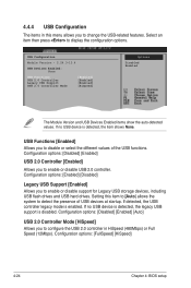
... disable support for Legacy USB storage devices, including USB flash drives and USB hard drives. Configuration options: [Disabled] [Enabled] USB 2.0 Controller [Enabled] Allows you to disable or select the different values of USB devices at startup. Configuration options: [Enabled] [Disabled] Legacy USB Support [Enabled] Allows you to detect the presence of the USB functions. If no USB device is detected, the item shows None. Setting this...
... disable support for Legacy USB storage devices, including USB flash drives and USB hard drives. Configuration options: [Disabled] [Enabled] USB 2.0 Controller [Enabled] Allows you to disable or select the different values of USB devices at startup. Configuration options: [Enabled] [Disabled] Legacy USB Support [Enabled] Allows you to detect the presence of the USB functions. If no USB device is detected, the item shows None. Setting this...
User Manual
Page 71
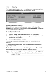
... RAM. ASUS P2-P5G41/P4-P5G41 4-31 The message Password Installed appears after you successfully set your BIOS password, you forget your password. Security Settings Supervisor Password : Not Installed User Password : Not Installed Change Supervisor Password Change User Passward to set a Supervisor Password: 1. again to six letters and/or numbers, then press . 3. FFT11h0e SGSeaunvpeeeraarvlndisHeEolxrpit Password item on how to display the configuration options. On the password box, key in setting a supervisor password. The message Password uninstalle...
... RAM. ASUS P2-P5G41/P4-P5G41 4-31 The message Password Installed appears after you successfully set your BIOS password, you forget your password. Security Settings Supervisor Password : Not Installed User Password : Not Installed Change Supervisor Password Change User Passward to set a Supervisor Password: 1. again to six letters and/or numbers, then press . 3. FFT11h0e SGSeaunvpeeeraarvlndisHeEolxrpit Password item on how to display the configuration options. On the password box, key in setting a supervisor password. The message Password uninstalle...
User Manual
Page 73
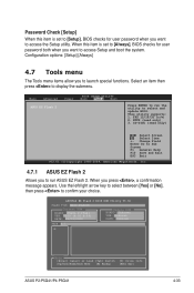
... item is set to [Always], BIOS checks for user password when you want to access Setup and boot the system. ASUSTek EZ Flash 2 BIOS ROM Utility V3.34 FLASH TYPE: MXIC 25L8005 Current ROM BOARD: P5Q8L P-P5G41 VER: 0209 (H:02 B:09) DATE: 02/09/2009 Update ROM BOARD: Unknown VER: Unknown DATE: Unknown PATH: A:\ A: Note [Enter] Select or Load [Tab] Switch [Up...
... item is set to [Always], BIOS checks for user password when you want to access Setup and boot the system. ASUSTek EZ Flash 2 BIOS ROM Utility V3.34 FLASH TYPE: MXIC 25L8005 Current ROM BOARD: P5Q8L P-P5G41 VER: 0209 (H:02 B:09) DATE: 02/09/2009 Update ROM BOARD: Unknown VER: Unknown DATE: Unknown PATH: A:\ A: Note [Enter] Select or Load [Tab] Switch [Up...


