User Manual
Page 33
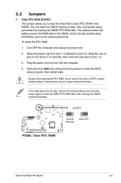
... the power cord and turn ON the computer. 4. Except when clearing the RTC RAM, never remove the cap on pins 2-3 for about 5-10 seconds, then move the jumper again to clear the ...CMOS RTC RAM data. Removing the cap will cause system boot failure. After clearing the CMOS, reinstall the... time, and system setup parameters by erasing the CMOS RTC RAM data. P5Q8L P5Q8L Clear RTC RAM CLRTC 12 23 Normal (Default) Clear RTC ASUS P2-P5G41/P4-P5G41 3-3 Clear RTC RAM (CLRTC) This jumper allows you to pins 1-2. 3.
... the power cord and turn ON the computer. 4. Except when clearing the RTC RAM, never remove the cap on pins 2-3 for about 5-10 seconds, then move the jumper again to clear the ...CMOS RTC RAM data. Removing the cap will cause system boot failure. After clearing the CMOS, reinstall the... time, and system setup parameters by erasing the CMOS RTC RAM data. P5Q8L P5Q8L Clear RTC RAM CLRTC 12 23 Normal (Default) Clear RTC ASUS P2-P5G41/P4-P5G41 3-3 Clear RTC RAM (CLRTC) This jumper allows you to pins 1-2. 3.
User Manual
Page 52
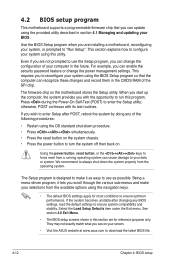
...designed to make your selections from a running operating system can cause damage to configure your system using the provided utility described in the CMOS RAM of the SPI chip. This requires you wish to enter Setup after changing any of the following procedures: • Restart using the navigation...using the OS standard shut-down the system properly from the operating system. The firmware chip on your screen. • Visit the ASUS website at www.asus.com to download the latest BIOS file. 4-12 Chapter 4: BIOS setup This section explains how to your data or system. For example...
...designed to make your selections from a running operating system can cause damage to configure your system using the provided utility described in the CMOS RAM of the SPI chip. This requires you wish to enter Setup after changing any of the following procedures: • Restart using the navigation...using the OS standard shut-down the system properly from the operating system. The firmware chip on your screen. • Visit the ASUS website at www.asus.com to download the latest BIOS file. 4-12 Chapter 4: BIOS setup This section explains how to your data or system. For example...
User Manual
Page 66
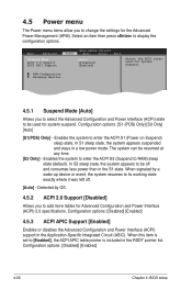
... Power menu items allow you to [Enabled], the ACPI APIC table pointer is set to change the settings for System Suspend. Enables the system to RAM) sleep state (default). Enables the system to enter the ACPI S3 (Suspend to enter the ACPI S1 (Power on Suspend) sleep state. Detected by a wake...
... Power menu items allow you to [Enabled], the ACPI APIC table pointer is set to change the settings for System Suspend. Enables the system to RAM) sleep state (default). Enables the system to enter the ACPI S3 (Suspend to enter the ACPI S1 (Power on Suspend) sleep state. Detected by a wake...
User Manual
Page 71
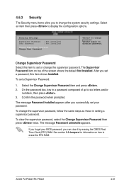
...NotEISnCstaExllietd. The message Password Installed appears after you successfully set your BIOS password, you can clear it by erasing the CMOS Real Time Clock (RTC) RAM. Select Screen Change Supervisor Password Select Item +- The message Password uninstalle appears. To clear the supervisor password, select the Change Supervisor Password then press...a Supervisor Password: 1. Select the Change Supervisor Password item and press . 2. On the password box, key in setting a supervisor password. To change the supervisor password. ASUS P2-P5G41/P4-P5G41 4-31
...NotEISnCstaExllietd. The message Password Installed appears after you successfully set your BIOS password, you can clear it by erasing the CMOS Real Time Clock (RTC) RAM. Select Screen Change Supervisor Password Select Item +- The message Password uninstalle appears. To clear the supervisor password, select the Change Supervisor Password then press...a Supervisor Password: 1. Select the Change Supervisor Password item and press . 2. On the password box, key in setting a supervisor password. To change the supervisor password. ASUS P2-P5G41/P4-P5G41 4-31
User Manual
Page 74
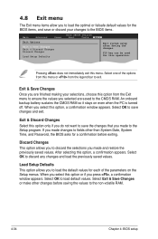
...before exiting. Select OK to the Setup program. F10 key can be used for a confirmation before saving the values to the non-volatile RAM. 4-34 Chapter 4: BIOS setup Exit & Discard Changes Select this option from the legend bar to load the default values for each of... Changes This option allows you press , a confirmation window appears. SelectSeolneecotf Ithteemoptions from this operation. An onboard backup battery sustains the CMOS RAM so it stays on the Setup menus. When you select this option or if you to load default values. Load Setup Defaults This option...
...before exiting. Select OK to the Setup program. F10 key can be used for a confirmation before saving the values to the non-volatile RAM. 4-34 Chapter 4: BIOS setup Exit & Discard Changes Select this option from the legend bar to load the default values for each of... Changes This option allows you press , a confirmation window appears. SelectSeolneecotf Ithteemoptions from this operation. An onboard backup battery sustains the CMOS RAM so it stays on the Setup menus. When you select this option or if you to load default values. Load Setup Defaults This option...
