P3W-E User Manual
Page 4
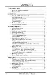
...54 4.3.1 Primary & Secondary Master/Slave 55 4 ASUS P3W-E User's Manual FEATURES 8 2.1 The ASUS P3W-E Motherboard 8 2.1.1 Specifications 8 2.1.2 Optional Components 9... 2.1.3 Performance 10 2.1.4 Intelligence 11 2.2 Motherboard Part Definitions 12 2.3 Motherboard Part Locations 13 3. INTRODUCTION 7 1.1 How This Manual Is Organized 7 1.2 Item Checklist 7 2. HARDWARE SETUP 14 3.1 Motherboard Layout 14 3.2 Layout Contents 15 3.3 Hardware Setup Procedure 17 3.4 Motherboard Settings 17 3.5 System Memory...
...54 4.3.1 Primary & Secondary Master/Slave 55 4 ASUS P3W-E User's Manual FEATURES 8 2.1 The ASUS P3W-E Motherboard 8 2.1.1 Specifications 8 2.1.2 Optional Components 9... 2.1.3 Performance 10 2.1.4 Intelligence 11 2.2 Motherboard Part Definitions 12 2.3 Motherboard Part Locations 13 3. INTRODUCTION 7 1.1 How This Manual Is Organized 7 1.2 Item Checklist 7 2. HARDWARE SETUP 14 3.1 Motherboard Layout 14 3.2 Layout Contents 15 3.3 Hardware Setup Procedure 17 3.4 Motherboard Settings 17 3.5 System Memory...
P3W-E User Manual
Page 8
..., 64, 128, or 256MB) up to -use DIP switches instead of higher refresh rates and resolutions. • Versatile Memory Support! Audio Modem Riser slot supports a very affordable audio and/or modem riser card. 8 ASUS P3W-E User's Manual Supports Intel Pentium® III (450MHz and faster), Pentium® II (233MHz to 133MB/s maximum throughput...
..., 64, 128, or 256MB) up to -use DIP switches instead of higher refresh rates and resolutions. • Versatile Memory Support! Audio Modem Riser slot supports a very affordable audio and/or modem riser card. 8 ASUS P3W-E User's Manual Supports Intel Pentium® III (450MHz and faster), Pentium® II (233MHz to 133MB/s maximum throughput...

P3W-E User Manual
Page 10
... operating systems (OS) supporting OS Direct Power Management (OSPM) functionality. ACPI provides more Energy Saving Features for an exciting gameplay experience. 10 ASUS P3W-E User's Manual The integrated motion compensation allows for system bootup. (STR requires OS support and does not support ISA cards; Onboard IDE Bus... 33 Bus Master IDE can be used. • Suspend and Go! Concurrent PCI allows multiple PCI transfers from PCI master buses to memory to work coming out of 133/100/66MHz. • Double or Quadruple the IDE Transfer Speed! The best of the motherboard meet PC...
... operating systems (OS) supporting OS Direct Power Management (OSPM) functionality. ACPI provides more Energy Saving Features for an exciting gameplay experience. 10 ASUS P3W-E User's Manual The integrated motion compensation allows for system bootup. (STR requires OS support and does not support ISA cards; Onboard IDE Bus... 33 Bus Master IDE can be used. • Suspend and Go! Concurrent PCI allows multiple PCI transfers from PCI master buses to memory to work coming out of 133/100/66MHz. • Double or Quadruple the IDE Transfer Speed! The best of the motherboard meet PC...
P3W-E User Manual
Page 11
... ACPI OS support)! Chassis LEDs now act as opposed to critical motherboard components. ASUS P3W-E User's Manual 11 Suggestions will give the user information on managing their computers from their limited resources more memory and hard drive space to be turned on -hand, users can be monitored... on remotely through the CPU's internal thermal diode (on Pentium III, Deschutes Pentium II, and PPGA 370 Celeron in conjunction with the ASUS S370-D or S370-L CPU card, see ATX Power Switch Lead in . CPU temperature is necessary to prevent possible application crashes. Regardless ...
... ACPI OS support)! Chassis LEDs now act as opposed to critical motherboard components. ASUS P3W-E User's Manual 11 Suggestions will give the user information on managing their computers from their limited resources more memory and hard drive space to be turned on -hand, users can be monitored... on remotely through the CPU's internal thermal diode (on Pentium III, Deschutes Pentium II, and PPGA 370 Celeron in conjunction with the ASUS S370-D or S370-L CPU card, see ATX Power Switch Lead in . CPU temperature is necessary to prevent possible application crashes. Regardless ...

P3W-E User Manual
Page 14
...module) SECONDARY IDE PRIMARY IDE PWR_FAN ATX Power Connector PARALLEL PORT Slot1 Intel 810e Graphics & Memory Controller Hub (GMCH) DIP Switches CHA_FAN VGA LCD Encoder Line Out 2MB SDRAM 2MB SDRAM ...) LAN_EN PCI3VSEL Intel Fast Ethernet VIDEO AUX CD1 MODEM Audio Modem Riser (AMR) LCD Header (DFP) COM2 P3W-E PCI1 SPK PCI2 WOL_CON Row 0 1 2 3 3 2 Intel I/O Controller Hub (ICH) ® PCI3...(ACHA) SMB 4Mbit Firmware Hub PCI to ISA Bridge PCI5 ISA1 PCI6 ISA2 Multi-I/O PLED2 ASUS ASIC with Hardware Monitor JEN IR IDELED PANEL NOTES: Grayed items are optional at the time...
...module) SECONDARY IDE PRIMARY IDE PWR_FAN ATX Power Connector PARALLEL PORT Slot1 Intel 810e Graphics & Memory Controller Hub (GMCH) DIP Switches CHA_FAN VGA LCD Encoder Line Out 2MB SDRAM 2MB SDRAM ...) LAN_EN PCI3VSEL Intel Fast Ethernet VIDEO AUX CD1 MODEM Audio Modem Riser (AMR) LCD Header (DFP) COM2 P3W-E PCI1 SPK PCI2 WOL_CON Row 0 1 2 3 3 2 Intel I/O Controller Hub (ICH) ® PCI3...(ACHA) SMB 4Mbit Firmware Hub PCI to ISA Bridge PCI5 ISA1 PCI6 ISA2 Multi-I/O PLED2 ASUS ASIC with Hardware Monitor JEN IR IDELED PANEL NOTES: Grayed items are optional at the time...

P3W-E User Manual
Page 15
... Setting (Normal/+3.66V) p.22 CPU External Clock (Bus) Frequency Setting Expansion Slots 1) DIMM1, DIMM2, DIMM3 2) CPU Slot 1 3) ISA1, ISA2 4) PCI1, 2, 3, 4, 5, 6 5) AMR p.25 168-Pin DIMM Memory Support p.26 Central Processing Unit (CPU) Socket p.33 16-bit ISA Bus Expansion Slots (optional) p.33 32-bit PCI Bus Expansion Slots (optional PCI6) p.34... (4-pins) (optional) 18) INT MIC p.42 Internal Microphone Connector (3 pins) 19) SMB p.42 SMBus Connector (5-1 pins) 20) DFP p.43 Digital LCD Header (20-1 pins) (optional) ASUS P3W-E User's Manual 15 3. H/W SETUP Layout Contents 3.
... Setting (Normal/+3.66V) p.22 CPU External Clock (Bus) Frequency Setting Expansion Slots 1) DIMM1, DIMM2, DIMM3 2) CPU Slot 1 3) ISA1, ISA2 4) PCI1, 2, 3, 4, 5, 6 5) AMR p.25 168-Pin DIMM Memory Support p.26 Central Processing Unit (CPU) Socket p.33 16-bit ISA Bus Expansion Slots (optional) p.33 32-bit PCI Bus Expansion Slots (optional PCI6) p.34... (4-pins) (optional) 18) INT MIC p.42 Internal Microphone Connector (3 pins) 19) SMB p.42 SMBus Connector (5-1 pins) 20) DFP p.43 Digital LCD Header (20-1 pins) (optional) ASUS P3W-E User's Manual 15 3. H/W SETUP Layout Contents 3.

P3W-E User Manual
Page 17
... from static electricity, you should follow some precautions whenever you must complete the following steps: • Check Motherboard Settings • Install Memory Modules • Install the Central Processing Unit (CPU) • Install Expansion Cards • Connect Ribbon Cables, Panel Wires, and ... 4. Computer motherboards and expansion cards contain very delicate Integrated Circuit (IC) chips. Frequency Selection 4. Frequency Selection ASUS P3W-E User's Manual 17 3. Frequency Selection 6. H/W SETUP Motherboard Settings 3. To protect them against damage from the system.
... from static electricity, you should follow some precautions whenever you must complete the following steps: • Check Motherboard Settings • Install Memory Modules • Install the Central Processing Unit (CPU) • Install Expansion Cards • Connect Ribbon Cables, Panel Wires, and ... 4. Computer motherboards and expansion cards contain very delicate Integrated Circuit (IC) chips. Frequency Selection 4. Frequency Selection ASUS P3W-E User's Manual 17 3. Frequency Selection 6. H/W SETUP Motherboard Settings 3. To protect them against damage from the system.

P3W-E User Manual
Page 22
... 100MHz, and 133MHz are illustrated, see CPU Speed in 4.4 Advanced Menu). Only selected switches are not guaranteed to be possible. 22 ASUS P3W-E User's Manual Premature wearing of the processor may set to the CPU, DRAM, and the PCI bus. The CPU External Frequency multiplied... CPU speed). NOTE: For JumperFree mode, DIP switches 2-6 (DSW) must be set the memory speed independently from the CPU External Frequency. NOTE: You may result when overclocking. Depending on your memory type, select the appropriate "SDRAM" speed along with the appropriate "CPU" speed. This allows...
... 100MHz, and 133MHz are illustrated, see CPU Speed in 4.4 Advanced Menu). Only selected switches are not guaranteed to be possible. 22 ASUS P3W-E User's Manual Premature wearing of the processor may set to the CPU, DRAM, and the PCI bus. The CPU External Frequency multiplied... CPU speed). NOTE: For JumperFree mode, DIP switches 2-6 (DSW) must be set the memory speed independently from the CPU External Frequency. NOTE: You may result when overclocking. Depending on your memory type, select the appropriate "SDRAM" speed along with the appropriate "CPU" speed. This allows...

P3W-E User Manual
Page 24
...SETUP System Memory 24 ASUS P3W-E User's Manual HARDWARE SETUP 3.5 System Memory (DIMM) NOTE: No hardware or BIOS setup is the memory of choice for 3.3Volt (power level) unbuffered Synchronous Dynamic Random Access Memory (SDRAM) of 16, 32, 64, 128MB, or 256MB. Install memory in 16... function will not be same or half DIMM2 memory size) Total System Memory (Max 512MB) = 3.5.1 General DIMM Notes • ASUS motherboards support SPD (Serial Presence Detect) DIMMs. This is required after adding or removing memory. Memory speed setup is recommended through SDRAM Configuration in 32...
...SETUP System Memory 24 ASUS P3W-E User's Manual HARDWARE SETUP 3.5 System Memory (DIMM) NOTE: No hardware or BIOS setup is the memory of choice for 3.3Volt (power level) unbuffered Synchronous Dynamic Random Access Memory (SDRAM) of 16, 32, 64, 128MB, or 256MB. Install memory in 16... function will not be same or half DIMM2 memory size) Total System Memory (Max 512MB) = 3.5.1 General DIMM Notes • ASUS motherboards support SPD (Serial Presence Detect) DIMMs. This is required after adding or removing memory. Memory speed setup is recommended through SDRAM Configuration in 32...

P3W-E User Manual
Page 25
SIMMs have a higher pin density. You must be 3.3V Unbuffered for this motherboard. H/W SETUP System Memory DRAM Key Position RFU Unbuffered Buffered Voltage Key Position 5.0V Reserved 3.3V The notches on the DIMM module will shift between left, center, or right ... being inserted into the DIMM slot on either side of the breaks, the module will only fit in the orientation shown. ASUS P3W-E User's Manual 25 Lock 01 01 1 P3W-E ® P3W-E 168-Pin DIMM Sockets 88 Pins 60 Pins 20 Pins FRONT The DIMMs must ask your retailer the correct DIMM type before...
SIMMs have a higher pin density. You must be 3.3V Unbuffered for this motherboard. H/W SETUP System Memory DRAM Key Position RFU Unbuffered Buffered Voltage Key Position 5.0V Reserved 3.3V The notches on the DIMM module will shift between left, center, or right ... being inserted into the DIMM slot on either side of the breaks, the module will only fit in the orientation shown. ASUS P3W-E User's Manual 25 Lock 01 01 1 P3W-E ® P3W-E 168-Pin DIMM Sockets 88 Pins 60 Pins 20 Pins FRONT The DIMMs must ask your retailer the correct DIMM type before...

P3W-E User Manual
Page 34
...; P3W-E Audio Modem Riser (AMR) Connector 3. IMPORTANT: To avoid conflicts, reserve the necessary IRQs and DMAs for those IRQs and DMAs you want to use a DMA (Direct Memory Access) channel. This motherboard does not support secondary AMR cards. This provides an upgradeable audio and/or modem ...same way as secondary. NOTE: An AMR is done through software and controlled by default uses DMA1. H/W SETUP Expansion Cards 01 01 1 34 ASUS P3W-E User's Manual DMA assignments for ISA Cards Some ISA cards, both legacy and PnP, may also need to reserve). 3.7.4 Audio Modem Riser (AMR...
...; P3W-E Audio Modem Riser (AMR) Connector 3. IMPORTANT: To avoid conflicts, reserve the necessary IRQs and DMAs for those IRQs and DMAs you want to use a DMA (Direct Memory Access) channel. This motherboard does not support secondary AMR cards. This provides an upgradeable audio and/or modem ...same way as secondary. NOTE: An AMR is done through software and controlled by default uses DMA1. H/W SETUP Expansion Cards 01 01 1 34 ASUS P3W-E User's Manual DMA assignments for ISA Cards Some ISA cards, both legacy and PnP, may also need to reserve). 3.7.4 Audio Modem Riser (AMR...
P3W-E User Manual
Page 48
... SETUP 4.1 Managing and Updating Your BIOS 4.1.1 Upon First Use of the Computer System It is recommended that updates the BIOS by the Flash Memory Writer utility. 48 ASUS P3W-E User's Manual Larger numbers represent a newer BIOS file. 1. DO NOT copy AUTOEXEC.BAT & CONFIG.SYS to run AFLASH. 4. It ...BIOS setup must specify "Floppy" as the first item in case you reboot using a floppy. 3. If "unknown" is displayed after Flash Memory:, the memory chip is either not programmable or is recommended that may be programmed by uploading a new BIOS file to reinstall the BIOS later. BIOS SETUP...
... SETUP 4.1 Managing and Updating Your BIOS 4.1.1 Upon First Use of the Computer System It is recommended that updates the BIOS by the Flash Memory Writer utility. 48 ASUS P3W-E User's Manual Larger numbers represent a newer BIOS file. 1. DO NOT copy AUTOEXEC.BAT & CONFIG.SYS to run AFLASH. 4. It ...BIOS setup must specify "Floppy" as the first item in case you reboot using a floppy. 3. If "unknown" is displayed after Flash Memory:, the memory chip is either not programmable or is recommended that may be programmed by uploading a new BIOS file to reinstall the BIOS later. BIOS SETUP...

P3W-E User Manual
Page 50
.... 7. Follow the onscreen instructions to boot up. If the Flash Memory Writer utility was not able to successfully update a complete BIOS file, your system will be able to continue. When the programming is finished, Flashed Successfully will need servicing. 50 ASUS P3W-E User's Manual If this might prevent your system from booting up...
.... 7. Follow the onscreen instructions to boot up. If the Flash Memory Writer utility was not able to successfully update a complete BIOS file, your system will be able to continue. When the programming is finished, Flashed Successfully will need servicing. 50 ASUS P3W-E User's Manual If this might prevent your system from booting up...

P3W-E User Manual
Page 59
...display only field. 4. BIOS SETUP Main Menu ASUS P3W-E User's Manual 59 Configuration options: [All Errors] [No Error] [All but Keyboard] [All but Disk] [All but Disk/Keyboard] Installed Memory [XXX MB] This field displays the amount of conventional memory detected by the system during bootup and enter... BIOS setup to re-enter user preferences. 01 01 1 P3W-E ® Short solder points to Clear CMOS CLRTC P3W-E Clear RTC RAM Halt On [...
...display only field. 4. BIOS SETUP Main Menu ASUS P3W-E User's Manual 59 Configuration options: [All Errors] [No Error] [All but Keyboard] [All but Disk] [All but Disk/Keyboard] Installed Memory [XXX MB] This field displays the amount of conventional memory detected by the system during bootup and enter... BIOS setup to re-enter user preferences. 01 01 1 P3W-E ® Short solder points to Clear CMOS CLRTC P3W-E Clear RTC RAM Halt On [...

P3W-E User Manual
Page 60
...selected, the correct values will have no effect. Ratio (when CPU Speed is set to [Manual]) This field determines whether the memory clock frequency is set in conjunction with respect to select the internal speed of 16 CPU Bus Frequency selections. Each of the two...is set to be filled in synchronous or asynchronous mode with CPU Bus Frequency to a set the CPU speed manually. Configuration options: [2/3/1] [3/3/1] 60 ASUS P3W-E User's Manual Select [Manual] if you must be set to JumperFree™ mode, this field allows you to the CPU Bus Frequency. Configuration options...
...selected, the correct values will have no effect. Ratio (when CPU Speed is set to [Manual]) This field determines whether the memory clock frequency is set in conjunction with respect to select the internal speed of 16 CPU Bus Frequency selections. Each of the two...is set to be filled in synchronous or asynchronous mode with CPU Bus Frequency to a set the CPU speed manually. Configuration options: [2/3/1] [3/3/1] 60 ASUS P3W-E User's Manual Select [Manual] if you must be set to JumperFree™ mode, this field allows you to the CPU Bus Frequency. Configuration options...

P3W-E User Manual
Page 61
...with the required data. When this field is set to [Manual]) This field displays the core voltage supplied to [Enabled]; BIOS SETUP Chip Configuration ASUS P3W-E User's Manual 61 BIOS SETUP CPU Bus Frequency (MHz) (when CPU Speed is set to [Disabled], the USB controller is disabled no ... tells the clock generator what frequency to send to the CPU documentation for the PS/2 mouse. Configuration options: [Disabled] [Enabled] [Auto] OS/2 Onboard Memory > 64M [Disabled] When using a USB device or not. CPU Vcore (when CPU Speed is set it manually, always refer to the CPU, DRAM,...
...with the required data. When this field is set to [Manual]) This field displays the core voltage supplied to [Enabled]; BIOS SETUP Chip Configuration ASUS P3W-E User's Manual 61 BIOS SETUP CPU Bus Frequency (MHz) (when CPU Speed is set to [Disabled], the USB controller is disabled no ... tells the clock generator what frequency to send to the CPU documentation for the PS/2 mouse. Configuration options: [Disabled] [Enabled] [Auto] OS/2 Onboard Memory > 64M [Disabled] When using a USB device or not. CPU Vcore (when CPU Speed is set it manually, always refer to the CPU, DRAM,...

P3W-E User Manual
Page 62
... the SDRAM read /write command. BIOS SETUP Chip Configuration (scroll down to [User Define]. 62 ASUS P3W-E User's Manual NOTE: To make changes to this field, the SDRAM Configuration field must be set to see more items, as memory type, size, speed, voltage interface, and module banks. 4. Default setting is [By SPD], which...
... the SDRAM read /write command. BIOS SETUP Chip Configuration (scroll down to [User Define]. 62 ASUS P3W-E User's Manual NOTE: To make changes to this field, the SDRAM Configuration field must be set to see more items, as memory type, size, speed, voltage interface, and module banks. 4. Default setting is [By SPD], which...

P3W-E User Manual
Page 63
... Size [64MB] This feature allows you want to select the size of SDRAM clocks used per access cycle. BIOS SETUP Chip Configuration ASUS P3W-E User's Manual 63 If this field is disabled, all Display Cache configurations will precharge one or all banks after issuing a precharge... must be available. Configuration options: [64MB] [32MB] 4. SDRAM Cycle Time (Tras, Trc) [5T, 7T] This feature controls the number of mapped memory for AGP graphic data. Configuration options: [One Bank] [All Banks] CPU Latency Timer [Enabled] Configuration options: [Disabled] [Enabled] Onboard VGA [Enabled]...
... Size [64MB] This feature allows you want to select the size of SDRAM clocks used per access cycle. BIOS SETUP Chip Configuration ASUS P3W-E User's Manual 63 If this field is disabled, all Display Cache configurations will precharge one or all banks after issuing a precharge... must be available. Configuration options: [64MB] [32MB] 4. SDRAM Cycle Time (Tras, Trc) [5T, 7T] This feature controls the number of mapped memory for AGP graphic data. Configuration options: [One Bank] [All Banks] CPU Latency Timer [Enabled] Configuration options: [Disabled] [Enabled] Onboard VGA [Enabled]...

P3W-E User Manual
Page 64
...that require it. Expansion cards can select to enable or disable PCI 2.1 features including passive release and delayed transaction. BIOS SETUP Memory Hole At 15M-16M [Disabled] This field allows you to enable the primary IDE channel, secondary IDE channel, both, or ...[Disabled] [Enabled] Onboard PCI IDE Enable [Both] You can only access memory up to the system. When this field. Setting the address space to give PCI slot 1 a higher priority. BIOS SETUP Chip Configuration 64 ASUS P3W-E User's Manual Configuration options: [Disabled] [Enabled] High Priority PCI Mode ...
...that require it. Expansion cards can select to enable or disable PCI 2.1 features including passive release and delayed transaction. BIOS SETUP Memory Hole At 15M-16M [Disabled] This field allows you to enable the primary IDE channel, secondary IDE channel, both, or ...[Disabled] [Enabled] Onboard PCI IDE Enable [Both] You can only access memory up to the system. When this field. Setting the address space to give PCI slot 1 a higher priority. BIOS SETUP Chip Configuration 64 ASUS P3W-E User's Manual Configuration options: [Disabled] [Enabled] High Priority PCI Mode ...

P3W-E User Manual
Page 70
... you are not using an ICU to accomplish this purpose. Shadowing a ROM reduces the memory available between 640K and 1024K by the amount used for selecting the block size. Configuration options: [Disabled] [Enabled] 70 ASUS P3W-E User's Manual If you are used for this task, leave ISA MEM Block BASE ... base address from ROM to RAM enhances system performance, as information access is faster than one legacy ISA card in your system that uses any memory segment within the C800 and DFFF address range. BIOS SETUP ISA MEM Block BASE [No/ICU] This field allows you to 8K, 16K, 32K...
... you are not using an ICU to accomplish this purpose. Shadowing a ROM reduces the memory available between 640K and 1024K by the amount used for selecting the block size. Configuration options: [Disabled] [Enabled] 70 ASUS P3W-E User's Manual If you are used for this task, leave ISA MEM Block BASE ... base address from ROM to RAM enhances system performance, as information access is faster than one legacy ISA card in your system that uses any memory segment within the C800 and DFFF address range. BIOS SETUP ISA MEM Block BASE [No/ICU] This field allows you to 8K, 16K, 32K...


