
P3C20000 User Manual
Page 5
...ASUS P3C2000 User's Manual 5 CONTENTS 4.2 BIOS Setup Program 55 4.2.1 BIOS Menu Bar 56 4.2.2 Legend Bar 56 4.3 Main Menu 58 4.3.1 Primary & Secondary Master/Slave 59 4.3.2 Keyboard Features 62 4.4 Advanced Menu 64 4.4.1 Chip Configuration 68 4.4.2 I/O Device Configuration 70 4.4.3 PCI Configuration 72 4.4.4 Shadow Configuration 75 4.5 Power Menu 76 4.5.1 Power...INF Update Utility for Intel 820 Chipset 92 5.6 Install ADI SoundMAX Audio Driver 93 5.7 Install ASUS PC Probe V2.10 94 5.8 Install ASUS Update V2.25 95 5.9 Install PC-Cillin 98 V4.06 96 5.10 Install ADOBE Acrobat ...
...ASUS P3C2000 User's Manual 5 CONTENTS 4.2 BIOS Setup Program 55 4.2.1 BIOS Menu Bar 56 4.2.2 Legend Bar 56 4.3 Main Menu 58 4.3.1 Primary & Secondary Master/Slave 59 4.3.2 Keyboard Features 62 4.4 Advanced Menu 64 4.4.1 Chip Configuration 68 4.4.2 I/O Device Configuration 70 4.4.3 PCI Configuration 72 4.4.4 Shadow Configuration 75 4.5 Power Menu 76 4.5.1 Power...INF Update Utility for Intel 820 Chipset 92 5.6 Install ADI SoundMAX Audio Driver 93 5.7 Install ASUS PC Probe V2.10 94 5.8 Install ASUS Update V2.25 95 5.9 Install PC-Cillin 98 V4.06 96 5.10 Install ADOBE Acrobat ...

P3C20000 User Manual
Page 8
FEATURES 2.1 The ASUS P3C2000 The ASUS P3C2000 motherboard is carefully designed for the demanding PC user who wants advanced features processed by the fastest processors. 2.1.1 Specifications • Latest Intel Processor Support Intel ... normal power is removed and through BIOS setup when JumperFree™ mode is even lower than the RTC used for AGP 4X mode, which can log chas- UltraDMA/66, which will improve cryptog- FEA TURES Specifications 2. sis panel open events into LDCM. raphy, digital signing, and other latest power computing features. 8 ASUS P3C2000 User...
FEATURES 2.1 The ASUS P3C2000 The ASUS P3C2000 motherboard is carefully designed for the demanding PC user who wants advanced features processed by the fastest processors. 2.1.1 Specifications • Latest Intel Processor Support Intel ... normal power is removed and through BIOS setup when JumperFree™ mode is even lower than the RTC used for AGP 4X mode, which can log chas- UltraDMA/66, which will improve cryptog- FEA TURES Specifications 2. sis panel open events into LDCM. raphy, digital signing, and other latest power computing features. 8 ASUS P3C2000 User...

P3C20000 User Manual
Page 10
...Supports UltraDMA/66, UltraDMA/33 (IDE DMA Mode 2), PIO Modes 3 & 4, and supports Enhanced IDE devices, such as required by PC 99. 10 ASUS P3C2000 User's Manual UltraDMA/66 is backward compatible with both DMA/33 and DMA and with existing DMA devices and systems so there is also implemented... four IDE devices in the OS, PCs can handle rates up to wait for a long time for future operating systems (OS) supporting OS Direct Power Management (OSPM) functionality. 2. FEA TURES Performance 2. ACPI provides more Energy Saving Features for system bootup. • PC 99 Compliancy: Both the ...
...Supports UltraDMA/66, UltraDMA/33 (IDE DMA Mode 2), PIO Modes 3 & 4, and supports Enhanced IDE devices, such as required by PC 99. 10 ASUS P3C2000 User's Manual UltraDMA/66 is backward compatible with both DMA/33 and DMA and with existing DMA devices and systems so there is also implemented... four IDE devices in the OS, PCs can handle rates up to wait for a long time for future operating systems (OS) supporting OS Direct Power Management (OSPM) functionality. 2. FEA TURES Performance 2. ACPI provides more Energy Saving Features for system bootup. • PC 99 Compliancy: Both the ...
P3C20000 User Manual
Page 11
... management. • System Resources Alert: Today's operating systems, such as information providers. Regardless of the setting, pushing the power button for future processors, so monitoring is in the world. • Message LED (requires ACPI OS support): Message LEDs now...resources are monitored to ensure stable current to prevent possible application crashes. ASUS P3C2000 User's Manual 11 A simple glimpse provides useful information to the user. • Peripheral Power Up: Keyboard or Mouse power up to critical motherboard components. FEATURES 2.1.4 Intelligence • Fan Status...
... management. • System Resources Alert: Today's operating systems, such as information providers. Regardless of the setting, pushing the power button for future processors, so monitoring is in the world. • Message LED (requires ACPI OS support): Message LEDs now...resources are monitored to ensure stable current to prevent possible application crashes. ASUS P3C2000 User's Manual 11 A simple glimpse provides useful information to the user. • Peripheral Power Up: Keyboard or Mouse power up to critical motherboard components. FEATURES 2.1.4 Intelligence • Fan Status...
P3C20000 User Manual
Page 12
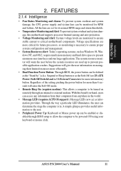
FEA TURES Motherboard Parts 2. FEATURES 2.2 Motherboard Parts See opposite page for locations. 1 CPU Slot 1 2 Intel 820 Memory Controller Hub (MCH) 3 ATX Power Connector for connection to an ATX power supply 4 Intel 82805 Memory Translator Hub (MTH) with Heatsink (not shown) 5 DIMM Sockets 6 Floppy Disk Drive Connector 7 Primary (BLUE) and Secondary IDE Connectors 8 Feature...) 22 Serial COM1 Port (B) 23 Parallel Port (T) 24 Serial COM2 Port (B) 25 USB Ports (USB1 & USB2) 26 PS/2 Mouse (T) / PS/2 Keyboard (B) Connector T: Top B: Bottom 12 ASUS P3C2000 User's Manual 2.
FEA TURES Motherboard Parts 2. FEATURES 2.2 Motherboard Parts See opposite page for locations. 1 CPU Slot 1 2 Intel 820 Memory Controller Hub (MCH) 3 ATX Power Connector for connection to an ATX power supply 4 Intel 82805 Memory Translator Hub (MTH) with Heatsink (not shown) 5 DIMM Sockets 6 Floppy Disk Drive Connector 7 Primary (BLUE) and Secondary IDE Connectors 8 Feature...) 22 Serial COM1 Port (B) 23 Parallel Port (T) 24 Serial COM2 Port (B) 25 USB Ports (USB1 & USB2) 26 PS/2 Mouse (T) / PS/2 Keyboard (B) Connector T: Top B: Bottom 12 ASUS P3C2000 User's Manual 2.

P3C20000 User Manual
Page 14
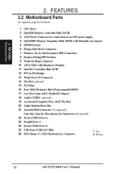
...2 3 VIDEO ADN# CD_IN MODEM Accelerated Graphics Port (AGP Pro) AUX AUD_EN1 AUD_EN2 SAFE_MODE Audio Codec PCI1 ® CR2032 3V Lithium Cell CMOS Power PCI2 10 32 P3C2000 Intel I/O Controller Hub (ICH) Low Pin SPK Count (LPC) Multi I/O 4Mbit Firmware Hub PCI3 WOL_CON PCI4 ISA1 PCI5 ISA2 PCI to ISA ... with Hardware Monitor WOR NO_REBOOT IR PANEL Grayed midboard items are optional at the time of purchase. DIP Switches 14 ASUS P3C2000 User's Manual ATX Power Connector PWR_FAN DIMM1 (64/72 bit, 168-pin module) DIMM2 (64/72 bit, 168-pin module) DIMM3 (64/72 bit, 168-...
...2 3 VIDEO ADN# CD_IN MODEM Accelerated Graphics Port (AGP Pro) AUX AUD_EN1 AUD_EN2 SAFE_MODE Audio Codec PCI1 ® CR2032 3V Lithium Cell CMOS Power PCI2 10 32 P3C2000 Intel I/O Controller Hub (ICH) Low Pin SPK Count (LPC) Multi I/O 4Mbit Firmware Hub PCI3 WOL_CON PCI4 ISA1 PCI5 ISA2 PCI to ISA ... with Hardware Monitor WOR NO_REBOOT IR PANEL Grayed midboard items are optional at the time of purchase. DIP Switches 14 ASUS P3C2000 User's Manual ATX Power Connector PWR_FAN DIMM1 (64/72 bit, 168-pin module) DIMM2 (64/72 bit, 168-pin module) DIMM3 (64/72 bit, 168-...
P3C20000 User Manual
Page 15
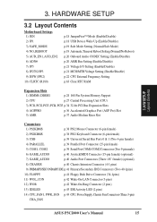
... Wake-On-LAN Connector (3 pins) 12) WOR p.42 Wake-On-Ring Connector (2 pins) 13) IDELED p.43 IDE Activity LED (2 pins) 14) CPU_FAN1, PWR_FAN p.43 CPU, Power Supply, Chassis Fan Connectors (Three 3-pin) CHA_FAN ASUS P3C2000 User's Manual 15 H/W SETUP Layout Contents 3.
... Wake-On-LAN Connector (3 pins) 12) WOR p.42 Wake-On-Ring Connector (2 pins) 13) IDELED p.43 IDE Activity LED (2 pins) 14) CPU_FAN1, PWR_FAN p.43 CPU, Power Supply, Chassis Fan Connectors (Three 3-pin) CHA_FAN ASUS P3C2000 User's Manual 15 H/W SETUP Layout Contents 3.
P3C20000 User Manual
Page 16
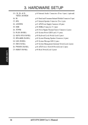
... Internal Speaker Connector (Two 2-pin) p.45 ATX Power Supply Connector (20 pins) p.46 SMBus Connector (5-1 pins) p.46 Power Supply Thermal Sensor Connector (2 pins) p.48 System Power LED Lead (3-1 pins) p.48 Keyboard Lock Switch ...Lead (2 pins) p.48 System Warning Speaker Connector (4 pins) p.48 System Message LED (2 pins) p.48 System Management Interrupt Switch Lead (2 pins) p.48 ATX Power / Soft-Off Switch Lead (2 pins) p.48 Reset Switch Lead (2 pins) 3. H/W SETUP 16 ASUS P3C2000...
... Internal Speaker Connector (Two 2-pin) p.45 ATX Power Supply Connector (20 pins) p.46 SMBus Connector (5-1 pins) p.46 Power Supply Thermal Sensor Connector (2 pins) p.48 System Power LED Lead (3-1 pins) p.48 Keyboard Lock Switch ...Lead (2 pins) p.48 System Warning Speaker Connector (4 pins) p.48 System Message LED (2 pins) p.48 System Management Interrupt Switch Lead (2 pins) p.48 ATX Power / Soft-Off Switch Lead (2 pins) p.48 Reset Switch Lead (2 pins) 3. H/W SETUP 16 ASUS P3C2000...

P3C20000 User Manual
Page 17
... grounded object or to touch the IC chips, leads or connectors, or other components. 4. H/W SETUP Motherboard Settings P3C2000 ® P3C2000 DIP Switches ON 12345 SW2 1. Frequency Selection 2. Frequency Selection 5. Ensure that came with the component whenever the components... a metal object, such as the power supply case. 3. Computer motherboards and expansion cards contain very delicate Integrated Circuit (IC) chips. 3. Frequency Selection 4. Unplug your computer. 1. Frequency Selection 3. Frequency Selection OFF ON ASUS P3C2000 User's Manual 17 To protect them ...
... grounded object or to touch the IC chips, leads or connectors, or other components. 4. H/W SETUP Motherboard Settings P3C2000 ® P3C2000 DIP Switches ON 12345 SW2 1. Frequency Selection 2. Frequency Selection 5. Ensure that came with the component whenever the components... a metal object, such as the power supply case. 3. Computer motherboards and expansion cards contain very delicate Integrated Circuit (IC) chips. 3. Frequency Selection 4. Unplug your computer. 1. Frequency Selection 3. Frequency Selection OFF ON ASUS P3C2000 User's Manual 17 To protect them ...

P3C20000 User Manual
Page 18
... Up (3-pin JP1) This allows you to Enable. 3 0 P3C2000 ® JP1 3 3 2 2 1 1 +5V (Default) +5VSB (Enable USB Device Wake Up) P3C2000 USB Device Wake Up 18 ASUS P3C2000 User's Manual The JumperFree™ mode allows processor settings to be set to disable or enable the USB device power up your computer. NOTE: In JumperFree™ mode...
... Up (3-pin JP1) This allows you to Enable. 3 0 P3C2000 ® JP1 3 3 2 2 1 1 +5V (Default) +5VSB (Enable USB Device Wake Up) P3C2000 USB Device Wake Up 18 ASUS P3C2000 User's Manual The JumperFree™ mode allows processor settings to be set to disable or enable the USB device power up your computer. NOTE: In JumperFree™ mode...
P3C20000 User Manual
Page 24
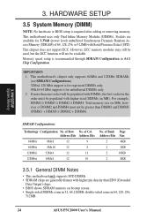
...supports 64Mbit and 128Mbit SDRAMs (see SDRAM Configurations). 32Mx4 128 Mbit support is for registered DIMMs only. 4Mx16 64 Mbit support is for 3.3Volt (power level) unbuffered Synchronous Dynamic Random Access Memory (SDRAM) of Bank Page Address Bits Size 2 4KB 2 2KB 2 16KB 2 8KB 3.5.1 General ...Memory Modules (DIMMs). of 64, 128, 256, or 512MB with DIMMs, the first socket in 64, 128, 256, 512MB. 24 ASUS P3C2000 User's Manual SDRAM Configurations Technology Configuration No. However, ECC memory modules may still be used, but the ECC function will be available. If...
...supports 64Mbit and 128Mbit SDRAMs (see SDRAM Configurations). 32Mx4 128 Mbit support is for registered DIMMs only. 4Mx16 64 Mbit support is for 3.3Volt (power level) unbuffered Synchronous Dynamic Random Access Memory (SDRAM) of Bank Page Address Bits Size 2 4KB 2 2KB 2 16KB 2 8KB 3.5.1 General ...Memory Modules (DIMMs). of 64, 128, 256, or 512MB with DIMMs, the first socket in 64, 128, 256, 512MB. 24 ASUS P3C2000 User's Manual SDRAM Configurations Technology Configuration No. However, ECC memory modules may still be used, but the ECC function will be available. If...

P3C20000 User Manual
Page 32
... temperature will shorten the processor lifetime and may be continuous with a strong retention clip. 4. Example of a correctly installed retention clip Example of power dissipation) for alarm. H/W SETUP CPU 32 ASUS P3C2000 User's Manual To prevent system overheat and/or damage, it is correctly installed onto the processor with no visible gap between the...
... temperature will shorten the processor lifetime and may be continuous with a strong retention clip. 4. Example of a correctly installed retention clip Example of power dissipation) for alarm. H/W SETUP CPU 32 ASUS P3C2000 User's Manual To prevent system overheat and/or damage, it is correctly installed onto the processor with no visible gap between the...

P3C20000 User Manual
Page 34
... this Motherboard PCI slot 1 PCI slot 2 PCI slot 3 PCI slot 4 PCI slot 5 AGP Pro slot Onboard USB controller Onboard audio/AMR INT-A shared - - - - shared - 34 ASUS P3C2000 User's Manual If your expansion card. 3.7.2 Assigning IRQs for expansion cards. IMPORTANT: If using PCI cards on the slot with the screw you intend to...
... this Motherboard PCI slot 1 PCI slot 2 PCI slot 3 PCI slot 4 PCI slot 5 AGP Pro slot Onboard USB controller Onboard audio/AMR INT-A shared - - - - shared - 34 ASUS P3C2000 User's Manual If your expansion card. 3.7.2 Assigning IRQs for expansion cards. IMPORTANT: If using PCI cards on the slot with the screw you intend to...

P3C20000 User Manual
Page 38
...first connector. 1) PS/2 Mouse Connector (Green 6-pin PS2KBMS) The system will direct IRQ12 to the PS/2 mouse if one is for connectors or power sources. H/W SETUP Connectors 2) PS/2 Keyboard Connector (Purple 6-pin PS2KBMS) This connection is not detected, expansion cards can use a DIN to your...size (large DIN) keyboard plugs. Pin 1 is detected. PS/2 Keyboard (6-pin Female) 38 ASUS P3C2000 User's Manual See PS/2 Mouse Function Control in .), with the red stripe to the power connector on hard drives and CD-ROM drives, but may be connected with the second drive ...
...first connector. 1) PS/2 Mouse Connector (Green 6-pin PS2KBMS) The system will direct IRQ12 to the PS/2 mouse if one is for connectors or power sources. H/W SETUP Connectors 2) PS/2 Keyboard Connector (Purple 6-pin PS2KBMS) This connection is not detected, expansion cards can use a DIN to your...size (large DIN) keyboard plugs. Pin 1 is detected. PS/2 Keyboard (6-pin Female) 38 ASUS P3C2000 User's Manual See PS/2 Mouse Function Control in .), with the red stripe to the power connector on hard drives and CD-ROM drives, but may be connected with the second drive ...

P3C20000 User Manual
Page 40
.... When any removable components. 3. Mic (pink) allows microphones to headphones or preferably powered speakers. Two wires should open and the motherboard will record a chassis intrusion event. CHASSIS 1 3 0 P3C2000 ® (Power Supply Stand By) +5Volt Chassis Signal Ground P3C2000 Chassis Open Alarm Lead 40 ASUS P3C2000 User's Manual H/W SETUP Connectors 7) Audio Port Connectors (Three 1/8" GAME_AUDIO) (optional) Line...
.... When any removable components. 3. Mic (pink) allows microphones to headphones or preferably powered speakers. Two wires should open and the motherboard will record a chassis intrusion event. CHASSIS 1 3 0 P3C2000 ® (Power Supply Stand By) +5Volt Chassis Signal Ground P3C2000 Chassis Open Alarm Lead 40 ASUS P3C2000 User's Manual H/W SETUP Connectors 7) Audio Port Connectors (Three 1/8" GAME_AUDIO) (optional) Line...

P3C20000 User Manual
Page 42
...) and that your system has an ATX power supply with at least 720mA +5V standby power. 3. The connector powers up the system when a ringup packet or signal is received through the internal modem card. H/W SETUP Connectors 3 0 P3C2000 ® WOR Ring# Ground 2 1 P3C2000 Wake-On-Ring Connector 42 ASUS P3C2000 User's Manual Appendix). 3. IMPORTANT: This feature requires that...
...) and that your system has an ATX power supply with at least 720mA +5V standby power. 3. The connector powers up the system when a ringup packet or signal is received through the internal modem card. H/W SETUP Connectors 3 0 P3C2000 ® WOR Ring# Ground 2 1 P3C2000 Wake-On-Ring Connector 42 ASUS P3C2000 User's Manual Appendix). 3. IMPORTANT: This feature requires that...

P3C20000 User Manual
Page 43
...) These connectors support cooling fans of the connector. WARNING! GND +12V Rotation 3 0 P3C2000 ® PWR_Fan CPU_Fan1 Rotation +12V GND Rotation +12V GND P3C2000 12-Volt Cooling Fan Power CHA_FAN ASUS P3C2000 User's Manual 43 3. The red wire should be positive, while the black should be ...monitored using ASUS PC Probe (see section 6. Depending on the fan manufacturer,...
...) These connectors support cooling fans of the connector. WARNING! GND +12V Rotation 3 0 P3C2000 ® PWR_Fan CPU_Fan1 Rotation +12V GND Rotation +12V GND P3C2000 12-Volt Cooling Fan Power CHA_FAN ASUS P3C2000 User's Manual 43 3. The red wire should be positive, while the black should be ...monitored using ASUS PC Probe (see section 6. Depending on the fan manufacturer,...

P3C20000 User Manual
Page 44
... pin definitions. H/W SETUP Connectors +5V (NC) IRRX GND IRTX 3 0 P3C2000 ® (NC) GND CIRRX CIR+5V SIR CIR P3C2000 Infrared Module Connector 44 ASUS P3C2000 User's Manual You must be Enabled in order to the CIR and SIR connectors simultaneously for use Consumer Infrared (CIR) power up. 3. An optional consumer infrared (CIR) set connects to...
... pin definitions. H/W SETUP Connectors +5V (NC) IRRX GND IRTX 3 0 P3C2000 ® (NC) GND CIRRX CIR+5V SIR CIR P3C2000 Infrared Module Connector 44 ASUS P3C2000 User's Manual You must be Enabled in order to the CIR and SIR connectors simultaneously for use Consumer Infrared (CIR) power up. 3. An optional consumer infrared (CIR) set connects to...

P3C20000 User Manual
Page 45
... connect a chassis mounted speaker to an ATX power supply. MIC2 3 0 P3C2000 ® 3 Ground SPKOUT 1 SPK P3C2000 Internal Speaker Connector 18) ATX Power Supply Connector (20-pin block ATXPWR) This connector...power supply will only insert in powering ON your system if your ATX power supply can supply at least 720mA +5VSB. 3 0 P3C2000 ® +3.3 Volts -12.0 Volts Ground Power Supply On Ground Ground Ground -5.0 Volts +5.0 Volts +5.0 Volts +3.3 Volts +3.3 Volts Ground +5.0 Volts Ground +5.0 Volts Ground Power Good +5V Standby +12.0 Volts P3C2000 ATX Power Connector ASUS P3C2000...
... connect a chassis mounted speaker to an ATX power supply. MIC2 3 0 P3C2000 ® 3 Ground SPKOUT 1 SPK P3C2000 Internal Speaker Connector 18) ATX Power Supply Connector (20-pin block ATXPWR) This connector...power supply will only insert in powering ON your system if your ATX power supply can supply at least 720mA +5VSB. 3 0 P3C2000 ® +3.3 Volts -12.0 Volts Ground Power Supply On Ground Ground Ground -5.0 Volts +5.0 Volts +5.0 Volts +3.3 Volts +3.3 Volts Ground +5.0 Volts Ground +5.0 Volts Ground Power Good +5V Standby +12.0 Volts P3C2000 ATX Power Connector ASUS P3C2000...

P3C20000 User Manual
Page 46
... monitoring, connect its thermal sensor cable to connect SMBus (System Management Bus) devices. Power Supply Thermal Sensor Connector 3 0 P3C2000 ® JTPWR P3C2000 Thermal Sensor Connector 46 ASUS P3C2000 User's Manual H/W SETUP Connectors 3. SMBCLK Ground SMBDATA +5V 3 0 P3C2000 ® SMB 1 P3C2000 SMBus Connector 20) Power Supply Thermal Sensor Connector (2-pin block JTPWR) If you to this connector. HARDWARE SETUP...
... monitoring, connect its thermal sensor cable to connect SMBus (System Management Bus) devices. Power Supply Thermal Sensor Connector 3 0 P3C2000 ® JTPWR P3C2000 Thermal Sensor Connector 46 ASUS P3C2000 User's Manual H/W SETUP Connectors 3. SMBCLK Ground SMBDATA +5V 3 0 P3C2000 ® SMB 1 P3C2000 SMBus Connector 20) Power Supply Thermal Sensor Connector (2-pin block JTPWR) If you to this connector. HARDWARE SETUP...


