
P3C-E User Manual
Page 1
R P3C-E Rambus™ Motherboard USER'S MANUAL
R P3C-E Rambus™ Motherboard USER'S MANUAL

P3C-E User Manual
Page 4
... 34 3.7.2 Assigning IRQs for Expansion Cards 34 3.7.3 Accelerated Graphics Port (AGP 36 3.7.4 Audio Modem Riser (AMR) Slot 37 3.8 External Connectors 38 3.9 Power Connection Procedures 47 4 ASUS P3C-E User's Manual INTRODUCTION 7 1.1 How This Manual Is Organized 7 1.2 Item Checklist 7 2. CONTENTS 1. FEATURES 8 2.1 The ASUS P3C-E 8 2.1.1 Specifications 8 2.1.2 Specifications-Optional Components 9 2.1.3 Performance 10 2.1.4 Intelligence 11 2.2 Motherboard Parts 12 3.
... 34 3.7.2 Assigning IRQs for Expansion Cards 34 3.7.3 Accelerated Graphics Port (AGP 36 3.7.4 Audio Modem Riser (AMR) Slot 37 3.8 External Connectors 38 3.9 Power Connection Procedures 47 4 ASUS P3C-E User's Manual INTRODUCTION 7 1.1 How This Manual Is Organized 7 1.2 Item Checklist 7 2. CONTENTS 1. FEATURES 8 2.1 The ASUS P3C-E 8 2.1.1 Specifications 8 2.1.2 Specifications-Optional Components 9 2.1.3 Performance 10 2.1.4 Intelligence 11 2.2 Motherboard Parts 12 3.

P3C-E User Manual
Page 5
APPENDIX 107 7.1 PCI-L101 Fast Ethernet Card 107 7.2 Modem Riser (optional 109 ASUS P3C-E User's Manual 5 SOFTWARE REFERENCE 97 6.1 ASUS PC Probe 97 6.2 Using YAMAHA XGPlayer 103 6.3 Using YAMAHA XGstudio Mixer 105 7. CONTENTS 4. BIOS SETUP 48 4.1 Managing and Updating ... Menu 54 4.4 Advanced Menu 60 4.5 Power Menu 72 4.6 Boot Menu 77 4.7 Exit Menu 79 5. SOFTWARE SETUP 81 5.1 Operating Systems 81 5.2 P3C Series Motherboard Support CD 82 5.3 Intel LDCM Administrator Setup 84 5.4 Intel LDCM Client Setup 86 5.5 INF Update Utility for Intel 820 Chipset 88 5.6 Install YAMAHA...
APPENDIX 107 7.1 PCI-L101 Fast Ethernet Card 107 7.2 Modem Riser (optional 109 ASUS P3C-E User's Manual 5 SOFTWARE REFERENCE 97 6.1 ASUS PC Probe 97 6.2 Using YAMAHA XGPlayer 103 6.3 Using YAMAHA XGstudio Mixer 105 7. CONTENTS 4. BIOS SETUP 48 4.1 Managing and Updating ... Menu 54 4.4 Advanced Menu 60 4.5 Power Menu 72 4.6 Boot Menu 77 4.7 Exit Menu 79 5. SOFTWARE SETUP 81 5.1 Operating Systems 81 5.2 P3C Series Motherboard Support CD 82 5.3 Intel LDCM Administrator Setup 84 5.4 Intel LDCM Client Setup 86 5.5 INF Update Utility for Intel 820 Chipset 88 5.6 Install YAMAHA...

P3C-E User Manual
Page 7
... (2) 3.5" floppy disk drives (1) Bag of spare jumpers (1) Support drivers and utilities (1) This Motherboard User's Manual ASUS DR2 DIMM riser (optional) ASUS S370 Series CPU card (optional) ASUS IrDA-compliant infrared module (optional) ASUS PCI-L101 Wake-On-LAN 10/100 ethernet card (optional) ASUS P3C-E User's Manual 7 INTRODUCTION Manual / Checklist 1. HARDWARE SETUP 4. INTRODUCTION 2. FEATURES 3. SOFTWARE SETUP 6. BIOS SETUP 5. If you...
... (2) 3.5" floppy disk drives (1) Bag of spare jumpers (1) Support drivers and utilities (1) This Motherboard User's Manual ASUS DR2 DIMM riser (optional) ASUS S370 Series CPU card (optional) ASUS IrDA-compliant infrared module (optional) ASUS PCI-L101 Wake-On-LAN 10/100 ethernet card (optional) ASUS P3C-E User's Manual 7 INTRODUCTION Manual / Checklist 1. HARDWARE SETUP 4. INTRODUCTION 2. FEATURES 3. SOFTWARE SETUP 6. BIOS SETUP 5. If you...

P3C-E User Manual
Page 8
...• PC800 Memory Support: Equipped with two Rambus Inline Memory Module (RIMM) sockets to 1GB. FEA TURES Specifications 2. FEATURES 2.1 The ASUS P3C-E The ASUS P3C-E motherboard is carefully designed for the demanding PC user who wants advanced features processed by using a 1X, 2X, or 4X mode bus. •... when JumperFree™ mode is required. 2. UltraDMA/66, which can transport twice the amount of the processor's external frequency. 8 ASUS P3C-E User's Manual Easy-to-use DIP switches instead of jumpers are necessary to meet the increase in 64, 96, 128, 192, 256, 512MB ...
...• PC800 Memory Support: Equipped with two Rambus Inline Memory Module (RIMM) sockets to 1GB. FEA TURES Specifications 2. FEATURES 2.1 The ASUS P3C-E The ASUS P3C-E motherboard is carefully designed for the demanding PC user who wants advanced features processed by using a 1X, 2X, or 4X mode bus. •... when JumperFree™ mode is required. 2. UltraDMA/66, which can transport twice the amount of the processor's external frequency. 8 ASUS P3C-E User's Manual Easy-to-use DIP switches instead of jumpers are necessary to meet the increase in 64, 96, 128, 192, 256, 512MB ...

P3C-E User Manual
Page 9
... EPP and ECP capabilities. 2. Provides Vcore and CPU/ RDRAM frequency adjustments, boot block write protection, and HD/SCSI/MO/ ZIP/CD/Floppy boot selection. ASUS P3C-E User's Manual 9 The onboard battery supports detection even when normal power is removed and through a new design, battery drain is even lower than the RTC used for... information between SMBus devices. • PCI/ISA Expansion Slots: Provides five 32-bit PCI (Rev. 2.2) expansion slots, which provides more control and protection over the motherboard. UART2 can log chassis panel open events into LDCM.
... EPP and ECP capabilities. 2. Provides Vcore and CPU/ RDRAM frequency adjustments, boot block write protection, and HD/SCSI/MO/ ZIP/CD/Floppy boot selection. ASUS P3C-E User's Manual 9 The onboard battery supports detection even when normal power is removed and through a new design, battery drain is even lower than the RTC used for... information between SMBus devices. • PCI/ISA Expansion Slots: Provides five 32-bit PCI (Rev. 2.2) expansion slots, which provides more control and protection over the motherboard. UART2 can log chassis panel open events into LDCM.

P3C-E User Manual
Page 10
...and Go: Suspend-to-RAM (STR) provides maximum power savings as an alternative to 66.6MB/s. This motherboard with two connectors that you do not fall asleep waiting for Windows 95/98/NT. ACPI provides more Energy...an ACPI-supported OS, such as Windows 98, must be ready around the clock, yet satisfy all ASUS smart series motherboards. With these features implemented in two channels. FEATURES 2.1.3 Performance • UltraPerformance: Onboard IDE Bus Master ... 3 & 4, and supports Enhanced IDE devices, such as required by PC 99. 10 ASUS P3C-E User's Manual FEA TURES Performance 2. 2.
...and Go: Suspend-to-RAM (STR) provides maximum power savings as an alternative to 66.6MB/s. This motherboard with two connectors that you do not fall asleep waiting for Windows 95/98/NT. ACPI provides more Energy...an ACPI-supported OS, such as Windows 98, must be ready around the clock, yet satisfy all ASUS smart series motherboards. With these features implemented in two channels. FEATURES 2.1.3 Performance • UltraPerformance: Onboard IDE Bus Master ... 3 & 4, and supports Enhanced IDE devices, such as required by PC 99. 10 ASUS P3C-E User's Manual FEA TURES Performance 2. 2.
P3C-E User Manual
Page 11
... set for more efficiently. • Dual Function Power Button: Through BIOS, the power button can determine the stage the computer is necessary to critical motherboard components. ASUS P3C-E User's Manual 11 All the fans are monitored to ensure stable current to ensure proper system configuration and management. • System Resources Alert: Today's operating systems...
... set for more efficiently. • Dual Function Power Button: Through BIOS, the power button can determine the stage the computer is necessary to critical motherboard components. ASUS P3C-E User's Manual 11 All the fans are monitored to ensure stable current to ensure proper system configuration and management. • System Resources Alert: Today's operating systems...
P3C-E User Manual
Page 12
FEATURES 2.2 Motherboard Parts See opposite page for locations. 1 ATX Power Connector for connection to an ATX power supply 2 CPU Slot 1 3 ... Hub (Programmable BIOS) 8 Low Pin Count (LPC) Multi-I/O Chipset 9 Floppy Disk Drive Connector 10 Feature Setting DIP Switches 11 ASUS ASIC with Hardware Monitor 12 PCI-to-ISA Bridge 13 Wake-On-Ring Connector 14 Wake-On-LAN Connector 15 ISA Slot (optional)... (T) 24 Serial COM1 Port (B) 25 USB Ports (USB1 & USB2) 26 PS/2 Mouse (T) / PS/2 Keyboard (B) Connector T: Top B: Bottom 12 ASUS P3C-E User's Manual 2. FEA TURES Motherboard Parts 2.
FEATURES 2.2 Motherboard Parts See opposite page for locations. 1 ATX Power Connector for connection to an ATX power supply 2 CPU Slot 1 3 ... Hub (Programmable BIOS) 8 Low Pin Count (LPC) Multi-I/O Chipset 9 Floppy Disk Drive Connector 10 Feature Setting DIP Switches 11 ASUS ASIC with Hardware Monitor 12 PCI-to-ISA Bridge 13 Wake-On-Ring Connector 14 Wake-On-LAN Connector 15 ISA Slot (optional)... (T) 24 Serial COM1 Port (B) 25 USB Ports (USB1 & USB2) 26 PS/2 Mouse (T) / PS/2 Keyboard (B) Connector T: Top B: Bottom 12 ASUS P3C-E User's Manual 2. FEA TURES Motherboard Parts 2.
P3C-E User Manual
Page 13
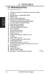
FEA TURES Motherboard Parts 2. FEATURES 2.2 Motherboard Parts...continued 1 23 4 5 6 78 26 25 24 23 22 21 20 19 18 17 16 15 14 13 12 11 10 9 ASUS P3C-E User's Manual 13 2.
FEA TURES Motherboard Parts 2. FEATURES 2.2 Motherboard Parts...continued 1 23 4 5 6 78 26 25 24 23 22 21 20 19 18 17 16 15 14 13 12 11 10 9 ASUS P3C-E User's Manual 13 2.
P3C-E User Manual
Page 14
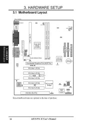
H/W SETUP Motherboard Layout 3. HARDWARE SETUP 3.1 Motherboard Layout T: Top B: Bottom T: Mouse PS2KBMS B: Keyboard USB T: USB1 B: USB2 ...AUX CD_IN JP10 Audio Modem Riser SPDIFIN TRCPU 1 2 RIMM0 RIMM1 3 4 Row Accelerated Graphics Port (AGP Pro) P3C-E PCI Slot 1 (PCI1) SECONDARY IDE PRIMARY IDE FLOPPY Intel I/O Controller Hub (ICH) CLRTC CR2032 3V Lithium ...PCI-to-ISA Bridge ISA Slot (SLOT2) IR DIP Switches TRPWR JP22 CHASSIS IDELED ASUS ASIC with Hardware Monitor PANEL Grayed midboard items are optional at the time of purchase. 14 ASUS P3C-E User's Manual 12345 O N 3.
H/W SETUP Motherboard Layout 3. HARDWARE SETUP 3.1 Motherboard Layout T: Top B: Bottom T: Mouse PS2KBMS B: Keyboard USB T: USB1 B: USB2 ...AUX CD_IN JP10 Audio Modem Riser SPDIFIN TRCPU 1 2 RIMM0 RIMM1 3 4 Row Accelerated Graphics Port (AGP Pro) P3C-E PCI Slot 1 (PCI1) SECONDARY IDE PRIMARY IDE FLOPPY Intel I/O Controller Hub (ICH) CLRTC CR2032 3V Lithium ...PCI-to-ISA Bridge ISA Slot (SLOT2) IR DIP Switches TRPWR JP22 CHASSIS IDELED ASUS ASIC with Hardware Monitor PANEL Grayed midboard items are optional at the time of purchase. 14 ASUS P3C-E User's Manual 12345 O N 3.
P3C-E User Manual
Page 15
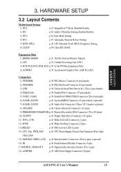
HARDWARE SETUP 3.2 Layout Contents Motherboard Settings 1) JP22 2) JP2 3) JP10 4) JP12 5) DSW (SW2) 6) CLRTC p.18 JumperFree™ Mode (Enable/Disable) p.18 Audio COntroller Setting (Enable/Disable) p.19 Safe Mode Setting p.19 ... p.44 Serial Infrared Module Connector (5-pin) 17)SPDIFIN, SPDIOOUT p.45 Digital Audio Interface Header (Two 2-pin) 18) ATXPWR p.45 ATX Power Supply Connectors (20 pins) ASUS P3C-E User's Manual 15 H/W SETUP Layout Contents 3. 3.
HARDWARE SETUP 3.2 Layout Contents Motherboard Settings 1) JP22 2) JP2 3) JP10 4) JP12 5) DSW (SW2) 6) CLRTC p.18 JumperFree™ Mode (Enable/Disable) p.18 Audio COntroller Setting (Enable/Disable) p.19 Safe Mode Setting p.19 ... p.44 Serial Infrared Module Connector (5-pin) 17)SPDIFIN, SPDIOOUT p.45 Digital Audio Interface Header (Two 2-pin) 18) ATXPWR p.45 ATX Power Supply Connectors (20 pins) ASUS P3C-E User's Manual 15 H/W SETUP Layout Contents 3. 3.
P3C-E User Manual
Page 17
...to a metal object, such as the power supply case. 3. Frequency Selection 2. Frequency Selection 1 2 3 4 P3C-E ON OFF P3C-E DIP Switches ASUS P3C-E User's Manual 17 Use a grounded wrist strap before you plug in the OFF position. Ensure that came with the component whenever...ON 1. 3. HARDWARE SETUP 3.3 Hardware Setup Procedure Before using DIP switches, the white block represents the switch's position. H/W SETUP Motherboard Settings 3. Place components on a grounded antistatic pad or on the bag that the ATX power supply is switched off before handling ...
...to a metal object, such as the power supply case. 3. Frequency Selection 2. Frequency Selection 1 2 3 4 P3C-E ON OFF P3C-E DIP Switches ASUS P3C-E User's Manual 17 Use a grounded wrist strap before you plug in the OFF position. Ensure that came with the component whenever...ON 1. 3. HARDWARE SETUP 3.3 Hardware Setup Procedure Before using DIP switches, the white block represents the switch's position. H/W SETUP Motherboard Settings 3. Place components on a grounded antistatic pad or on the bag that the ATX power supply is switched off before handling ...

P3C-E User Manual
Page 18
...the JumperFree™ mode. The JumperFree™ mode allows processor settings to be set to OFF. Setting Enable Disable JP2 [1-2] (default) [2-3] P3C-E JP2 1 2 3 Enable 1 2 3 Disable P3C-E Audio Controller Setting 18 ASUS P3C-E User's Manual NOTE: In JumperFree™ mode, all dip switches (DSW) must also be disabled. HARDWARE SETUP 1) JumperFree™ Mode (JP22) This ...Audio Modem Riser (AMR) Slot). Disable the onboard audio if you to enable or disable the onboard 32-bit PCI audio controller (optional component). H/W SETUP Motherboard Settings 3. ON 12345 3.
...the JumperFree™ mode. The JumperFree™ mode allows processor settings to be set to OFF. Setting Enable Disable JP2 [1-2] (default) [2-3] P3C-E JP2 1 2 3 Enable 1 2 3 Disable P3C-E Audio Controller Setting 18 ASUS P3C-E User's Manual NOTE: In JumperFree™ mode, all dip switches (DSW) must also be disabled. HARDWARE SETUP 1) JumperFree™ Mode (JP22) This ...Audio Modem Riser (AMR) Slot). Disable the onboard audio if you to enable or disable the onboard 32-bit PCI audio controller (optional component). H/W SETUP Motherboard Settings 3. ON 12345 3.

P3C-E User Manual
Page 19
... Mode JP10 [1-2] (default) [2-3] JP10 1 23 123 Normal Safe Mode P3C-E (Default) P3C-E Safe Mode Reboot Setting 4) Automatic Timeout Reboot Setting (JP12) The motherboard is no way to disable auto-reboot. H/W SETUP Motherboard Settings JP12 1 23 123 P3C-E Normal No Reboot (Default) P3C-E Automatic Timeout Reboot Setting ASUS P3C-E User's Manual 19 Exceeding the specified multiple may correct any problem...
... Mode JP10 [1-2] (default) [2-3] JP10 1 23 123 Normal Safe Mode P3C-E (Default) P3C-E Safe Mode Reboot Setting 4) Automatic Timeout Reboot Setting (JP12) The motherboard is no way to disable auto-reboot. H/W SETUP Motherboard Settings JP12 1 23 123 P3C-E Normal No Reboot (Default) P3C-E Automatic Timeout Reboot Setting ASUS P3C-E User's Manual 19 Exceeding the specified multiple may correct any problem...

P3C-E User Manual
Page 20
Multiple in place of the CPU's External frequency. H/W SETUP Motherboard Settings 20 ASUS P3C-E User's Manual In JumperFree mode, all dip switches (DSW-1-DSW-5) must use BIOS setup in 4.4 Advanced Menu of the BIOS setup to OFF. 2. If the Frequency Multiple .... IMPORTANT: 1. DSW (SW2) ON 12345 ON 12345 ON 12345 CPU → 100MHz PCI → 33.6MHz 103MHz 34.3MHz 105MHz 34.9MHz P3C-E ON 12345 ON 12345 ON 12345 P3C-E CPU External Clock (BUS) Frequency Selection CPU →133.9MHz PCI → 33.4MHz 138MHz (JumperFree Mode) 34.5MHz NOTE: If your...
Multiple in place of the CPU's External frequency. H/W SETUP Motherboard Settings 20 ASUS P3C-E User's Manual In JumperFree mode, all dip switches (DSW-1-DSW-5) must use BIOS setup in 4.4 Advanced Menu of the BIOS setup to OFF. 2. If the Frequency Multiple .... IMPORTANT: 1. DSW (SW2) ON 12345 ON 12345 ON 12345 CPU → 100MHz PCI → 33.6MHz 103MHz 34.3MHz 105MHz 34.9MHz P3C-E ON 12345 ON 12345 ON 12345 P3C-E CPU External Clock (BUS) Frequency Selection CPU →133.9MHz PCI → 33.4MHz 138MHz (JumperFree Mode) 34.5MHz NOTE: If your...

P3C-E User Manual
Page 21
...] [OFF] [OFF] [O N ] [OFF] [OFF] [OFF] [OFF] [OFF] NOTE: For updated processor settings, visit the ASUS web site (see ASUS CONTACT INFORMATION) ASUS P3C-E User's Manual 21 Overclocking can result in system instability or even shortening the life of the processor. H/W SETUP Motherboard Settings 3. HARDWARE SETUP External Frequency Table The following table is for use by experienced...
...] [OFF] [OFF] [O N ] [OFF] [OFF] [OFF] [OFF] [OFF] NOTE: For updated processor settings, visit the ASUS web site (see ASUS CONTACT INFORMATION) ASUS P3C-E User's Manual 21 Overclocking can result in system instability or even shortening the life of the processor. H/W SETUP Motherboard Settings 3. HARDWARE SETUP External Frequency Table The following table is for use by experienced...

P3C-E User Manual
Page 22
... 192, and 256MB densities. To use when SDRAM is required after adding or removing memory. C-RIMMs (Continuity RIMM) must be used in this motherboard, an ASUS DIMM Riser (ASUS DR2) must be populated) TOTAL SYSTEM MEMORY (RDRAM: 1GB Max) / (SDRAM: 1GB Max) Subtotal x 1 x 1 = IMPORTANT 1. ...SDRAM+Riser or vice versa. 22 ASUS P3C-E User's Manual H/W SETUP System Memory 3. The riser must be populated in any combination as memory, the RIMM sockets must be populated) RIMM1 (Rows 2&3) RDRAM (do not use SDRAM with C-RIMM. 3. This motherboard has two Rambus Inline Memory Module (...
... 192, and 256MB densities. To use when SDRAM is required after adding or removing memory. C-RIMMs (Continuity RIMM) must be used in this motherboard, an ASUS DIMM Riser (ASUS DR2) must be populated) TOTAL SYSTEM MEMORY (RDRAM: 1GB Max) / (SDRAM: 1GB Max) Subtotal x 1 x 1 = IMPORTANT 1. ...SDRAM+Riser or vice versa. 22 ASUS P3C-E User's Manual H/W SETUP System Memory 3. The riser must be populated in any combination as memory, the RIMM sockets must be populated) RIMM1 (Rows 2&3) RDRAM (do not use SDRAM with C-RIMM. 3. This motherboard has two Rambus Inline Memory Module (...

P3C-E User Manual
Page 25
.... H/W SETUP System Memory 3. Tighten captive nuts to 64MB on J1M1. Doing so could damage your motherboard. If necessary, push the ejectors inward to case CAPTIVE NUT (back of the DIMM sockets on the other side. ASUS P3C-E User's Manual 25 HARDWARE SETUP MOUNTING NOTCH SDRAM NOTCH KEYS CONNECTORS RIBS (inside socket) RIMM0 (top view...
.... H/W SETUP System Memory 3. Tighten captive nuts to 64MB on J1M1. Doing so could damage your motherboard. If necessary, push the ejectors inward to case CAPTIVE NUT (back of the DIMM sockets on the other side. ASUS P3C-E User's Manual 25 HARDWARE SETUP MOUNTING NOTCH SDRAM NOTCH KEYS CONNECTORS RIBS (inside socket) RIMM0 (top view...

P3C-E User Manual
Page 26
This is the memory of the strict timing issues involved under this motherboard. To determine the DIMM type, check the notches on the DIMMs (see figure below). 168-Pin ...the wrong type from being inserted into the DIMM socket on the riser because of choice for this speed. • This motherboard supports SPD (Serial Presence Detect) memory modules. HARDWARE SETUP General DIMM Notes • PC100-compliant modules must be 3.3V Unbuffered.... • The DIMMs must ask your retailer the correct DIMM type before purchasing. H/W SETUP System Memory 26 ASUS P3C-E User's Manual 3.
This is the memory of the strict timing issues involved under this motherboard. To determine the DIMM type, check the notches on the DIMMs (see figure below). 168-Pin ...the wrong type from being inserted into the DIMM socket on the riser because of choice for this speed. • This motherboard supports SPD (Serial Presence Detect) memory modules. HARDWARE SETUP General DIMM Notes • PC100-compliant modules must be 3.3V Unbuffered.... • The DIMMs must ask your retailer the correct DIMM type before purchasing. H/W SETUP System Memory 26 ASUS P3C-E User's Manual 3.


