P2B-F User Manual
Page 1
R P2B-F Pentium® III / II / CeleronTM Motherboard USER'S MANUAL
R P2B-F Pentium® III / II / CeleronTM Motherboard USER'S MANUAL
P2B-F User Manual
Page 4
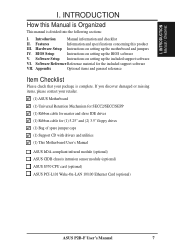
... of Standard CMOS Setup 38 BIOS Features Setup 41 Details of the ASUS P2B-F Motherboard 8 The ASUS P2B-F Motherboard 11 III. INTRODUCTION 7 How this Manual is Organized 7 Item Checklist 7 II. FEATURES 8 Features of BIOS Features Setup 41 4 ASUS P2B-F User's Manual HARDWARE SETUP 12 Layout of the ASUS P2B-F Motherboard 12 Hardware Setup Steps 14 1. BIOS SETUP 34 Flash Memory Writer...
... of Standard CMOS Setup 38 BIOS Features Setup 41 Details of the ASUS P2B-F Motherboard 8 The ASUS P2B-F Motherboard 11 III. INTRODUCTION 7 How this Manual is Organized 7 Item Checklist 7 II. FEATURES 8 Features of BIOS Features Setup 41 4 ASUS P2B-F User's Manual HARDWARE SETUP 12 Layout of the ASUS P2B-F Motherboard 12 Hardware Setup Steps 14 1. BIOS SETUP 34 Flash Memory Writer...
P2B-F User Manual
Page 7
... of spare jumper caps (1) Support CD with drivers and utilities (1) This Motherboard User's Manual ASUS IrDA-compliant infrared module (optional) ASUS CIDB chassis intrusion sensor module (optional) ASUS S370 CPU card (optional) ASUS PCI-L101 Wake-On-LAN 10/100 Ethernet Card (optional) ASUS P2B-F User's Manual 7 Appendix Optional items and general reference Item Checklist Please check...
... of spare jumper caps (1) Support CD with drivers and utilities (1) This Motherboard User's Manual ASUS IrDA-compliant infrared module (optional) ASUS CIDB chassis intrusion sensor module (optional) ASUS S370 CPU card (optional) ASUS PCI-L101 Wake-On-LAN 10/100 Ethernet Card (optional) ASUS P2B-F User's Manual 7 Appendix Optional items and general reference Item Checklist Please check...
P2B-F User Manual
Page 8
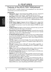
..., 128, or 256MB) up to examine and manage system status information, such as Tape Backup and CD-ROM, and LS-120 drives. 8 ASUS P2B-F User's Manual FEATURES Features of the ASUS P2B-F Motherboard The ASUS P2B-F is shared with a PCI slot. • Multi-I /O subsystems and front-side bus (FSB) platform, which boosts the traditional 66MHz external bus...
..., 128, or 256MB) up to examine and manage system status information, such as Tape Backup and CD-ROM, and LS-120 drives. 8 ASUS P2B-F User's Manual FEATURES Features of the ASUS P2B-F Motherboard The ASUS P2B-F is shared with a PCI slot. • Multi-I /O subsystems and front-side bus (FSB) platform, which boosts the traditional 66MHz external bus...
P2B-F User Manual
Page 9
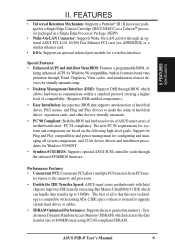
... need to upgrade current hard drives or cables. • SDRAM Optimized Performance: Supports the new generation memory - ASUS P2B-F User's Manual 9 The best of motherboards meet PC'98 compliancy. FEATURES Specifications II. Synchronous Dynamic Random Access Memory (SDRAM) which allows hardware to communicate ...: Support for Plug and Play compatibility and power management for Windows 95/98/NT. • Symbios SCSI BIOS: Supports optional ASUS SCSI controller cards through the onboard SYMBIOS firmware. Special Features: • Enhanced ACPI and Anti-Boot Virus BIOS: Features a ...
... need to upgrade current hard drives or cables. • SDRAM Optimized Performance: Supports the new generation memory - ASUS P2B-F User's Manual 9 The best of motherboards meet PC'98 compliancy. FEATURES Specifications II. Synchronous Dynamic Random Access Memory (SDRAM) which allows hardware to communicate ...: Support for Plug and Play compatibility and power management for Windows 95/98/NT. • Symbios SCSI BIOS: Supports optional ASUS SCSI controller cards through the onboard SYMBIOS firmware. Special Features: • Enhanced ACPI and Anti-Boot Virus BIOS: Features a ...
P2B-F User Manual
Page 10
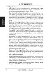
...supply, and system fans can determine the stage the computer is necessary to be turned on remotely through the optional ASUS CIDB module and Intel LDCM. 10 ASUS P2B-F User's Manual All fans are monitored to ensure stable voltage to present enormous user interfaces and run large applications. ... OS support): Turbo LEDs now act as Windows 95/98/ NT and OS/2, require much more memory and hard drive space to critical motherboard components. With this benefit on the BIOS setting (see Power Management Setup under BIOS SETUP). Voltage specifications are more critical for more efficiently...
...supply, and system fans can determine the stage the computer is necessary to be turned on remotely through the optional ASUS CIDB module and Intel LDCM. 10 ASUS P2B-F User's Manual All fans are monitored to ensure stable voltage to present enormous user interfaces and run large applications. ... OS support): Turbo LEDs now act as Windows 95/98/ NT and OS/2, require much more memory and hard drive space to critical motherboard components. With this benefit on the BIOS setting (see Power Management Setup under BIOS SETUP). Voltage specifications are more critical for more efficiently...
P2B-F User Manual
Page 11
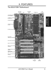
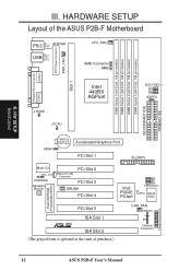
FEATURES Motherboard Parts II. FEATURES The ASUS P2B-F Motherboard T: PS/2 Mouse B: PS/2 Keyboard T: USB Conn 1 B:USB Conn 2 B:COM1 T: Parallel B:Serial ATX Power Connector Slot 1 Intel 440BX AGPset 4 DIMM Slots IDE Connectors B:COM2 Accelerated Graphics Port 5 PCI Slots Multi-I/O Wake-On-LAN Connector Hardware Monitor (optional) Programmable 2Mbit Flash EEPROM SB-Link™ Connector 2 ISA Slots Intel PIIX4E PCIset Floppy Connector ASUS P2B-F User's Manual 11 II.
FEATURES Motherboard Parts II. FEATURES The ASUS P2B-F Motherboard T: PS/2 Mouse B: PS/2 Keyboard T: USB Conn 1 B:USB Conn 2 B:COM1 T: Parallel B:Serial ATX Power Connector Slot 1 Intel 440BX AGPset 4 DIMM Slots IDE Connectors B:COM2 Accelerated Graphics Port 5 PCI Slots Multi-I/O Wake-On-LAN Connector Hardware Monitor (optional) Programmable 2Mbit Flash EEPROM SB-Link™ Connector 2 ISA Slots Intel PIIX4E PCIset Floppy Connector ASUS P2B-F User's Manual 11 II.
P2B-F User Manual
Page 12
... module) DIMM Socket 3 (64/72 bit, 168 pin module) SECONDARY IDE PRIMARY IDE III. H/W SETUP Board Layout III. HARDWARE SETUP Layout of the ASUS P2B-F Motherboard PS/2 TOP: Mouse ATXPWR BOTTOM: Keyboard TOP: USB USB 1 BOTTOM: USB 2 CPU_FAN SMB Connector SMB ATX Power Connector PWR_FAN COM 1 Slot 1 Parallel...CHASSIS Hardware Monitor Wake-On-LAN Connector PCI Slot 2 PCI Slot 3 SBLINK PCI Slot 4 Intel PIIX4E PCIset BF0 BF1 BF2 BF3 FREQ MULT CLRTC ASUS ASIC PCI Slot 5 ISA Slot 1 R ISA Slot 2 (The grayed item is optional at the time of purchase.) CHA_FAN IDELED IR Infrared ...
... module) DIMM Socket 3 (64/72 bit, 168 pin module) SECONDARY IDE PRIMARY IDE III. H/W SETUP Board Layout III. HARDWARE SETUP Layout of the ASUS P2B-F Motherboard PS/2 TOP: Mouse ATXPWR BOTTOM: Keyboard TOP: USB USB 1 BOTTOM: USB 2 CPU_FAN SMB Connector SMB ATX Power Connector PWR_FAN COM 1 Slot 1 Parallel...CHASSIS Hardware Monitor Wake-On-LAN Connector PCI Slot 2 PCI Slot 3 SBLINK PCI Slot 4 Intel PIIX4E PCIset BF0 BF1 BF2 BF3 FREQ MULT CLRTC ASUS ASIC PCI Slot 5 ISA Slot 1 R ISA Slot 2 (The grayed item is optional at the time of purchase.) CHA_FAN IDELED IR Infrared ...

P2B-F User Manual
Page 13
III. H/W SETUP Layout Contents III. ASUS P2B-F User's Manual 13 HARDWARE SETUP Motherboard Settings 1) KBWK 2) AGPFS 3) FS0, FS1, FS2, FS3 4) BF0, BF1, BF2, BF3 p. 15 Keyboard Power Up p. 15 AGP Bus Frequency Selection p. 16 CPU External Clock (BUS) ...) IR p. 30 Infrared Port Module Connector (5 pins) 12) SBLINK p. 30 SB-Link™ Connector (6-1 pins) 13) SMB p. 30 SMBus Connector (3 pins) 14) ATXPWR p. 31 ATX Motherboard Power Connector (20 pins) 15) CHASSIS p. 31 Chassis Intrusion Alarm Lead (3 pins) 16) PWR.LED (PANEL) 17) KEYLOCK (PANEL) 18) SPEAKER (PANEL) 19) MSG.LED...
III. H/W SETUP Layout Contents III. ASUS P2B-F User's Manual 13 HARDWARE SETUP Motherboard Settings 1) KBWK 2) AGPFS 3) FS0, FS1, FS2, FS3 4) BF0, BF1, BF2, BF3 p. 15 Keyboard Power Up p. 15 AGP Bus Frequency Selection p. 16 CPU External Clock (BUS) ...) IR p. 30 Infrared Port Module Connector (5 pins) 12) SBLINK p. 30 SB-Link™ Connector (6-1 pins) 13) SMB p. 30 SMBus Connector (3 pins) 14) ATXPWR p. 31 ATX Motherboard Power Connector (20 pins) 15) CHASSIS p. 31 Chassis Intrusion Alarm Lead (3 pins) 16) PWR.LED (PANEL) 17) KEYLOCK (PANEL) 18) SPEAKER (PANEL) 19) MSG.LED...
P2B-F User Manual
Page 14
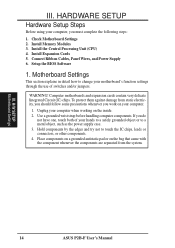
... against damage from the system. HARDWARE SETUP Hardware Setup Steps Before using your computer, you work on your computer. 1. Computer motherboards and expansion cards contain very delicate Integrated Circuit (IC) chips. Unplug your hands to a safely grounded object or to touch... components on a grounded antistatic pad or on the inside. 2. H/W SETUP Motherboard Settings 14 ASUS P2B-F User's Manual Install Expansion Cards 5. Connect Ribbon Cables, Panel Wires, and Power Supply 6. III. Check Motherboard Settings 2. Install Memory Modules 3. If you do not have one, touch ...
... against damage from the system. HARDWARE SETUP Hardware Setup Steps Before using your computer, you work on your computer. 1. Computer motherboards and expansion cards contain very delicate Integrated Circuit (IC) chips. Unplug your hands to a safely grounded object or to touch... components on a grounded antistatic pad or on the inside. 2. H/W SETUP Motherboard Settings 14 ASUS P2B-F User's Manual Install Expansion Cards 5. Connect Ribbon Cables, Panel Wires, and Power Supply 6. III. Check Motherboard Settings 2. Install Memory Modules 3. If you do not have one, touch ...
P2B-F User Manual
Page 15
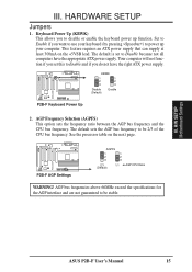
...bus frequency to power up function. HARDWARE SETUP Jumpers 1. The default is set this to be 2/3 of the CPU bus frequency. ASUS P2B-F User's Manual 15 III. AGP bus frequencies above 66MHz exceed the specifications for the AGP interface and are not guaranteed to Enable...next page. KBWK 1 1 2 2 3 3 Disable (Default) Enable P2B-F Keyboard Power Up 2. AGP Frequency Selection (AGPFS) This option sets the frequency ratio between the AGP bus frequency and the CPU bus frequency. H/W SETUP Motherboard Settings III. Your computer will not function if you want to Disable ...
...bus frequency to power up function. HARDWARE SETUP Jumpers 1. The default is set this to be 2/3 of the CPU bus frequency. ASUS P2B-F User's Manual 15 III. AGP bus frequencies above 66MHz exceed the specifications for the AGP interface and are not guaranteed to Enable...next page. KBWK 1 1 2 2 3 3 Disable (Default) Enable P2B-F Keyboard Power Up 2. AGP Frequency Selection (AGPFS) This option sets the frequency ratio between the AGP bus frequency and the CPU bus frequency. H/W SETUP Motherboard Settings III. Your computer will not function if you want to Disable ...
P2B-F User Manual
Page 17
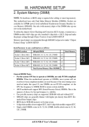
...to 66MHz RAM to operate at 100MHz, most system will not even boot if non-compliant modules are available for best performance vs. HARDWARE SETUP 2. ASUS P2B-F User's Manual 17 If your DIMMs are generally thinner with 9 chips per side (standard 8 chips/side + 1 ECC chip) and make ...64, 128, 256MB x1 Total System Memory (Max 1024MB) = General DIMM Notes • For the system CPU bus to ensure system stability. • ASUS motherboards support SPD (Serial Presence Detect) DIMMs. This is the memory of the DIMM takes up one row on bootup screen. • 8 chips/side modules do...
...to 66MHz RAM to operate at 100MHz, most system will not even boot if non-compliant modules are available for best performance vs. HARDWARE SETUP 2. ASUS P2B-F User's Manual 17 If your DIMMs are generally thinner with 9 chips per side (standard 8 chips/side + 1 ECC chip) and make ...64, 128, 256MB x1 Total System Memory (Max 1024MB) = General DIMM Notes • For the system CPU bus to ensure system stability. • ASUS motherboards support SPD (Serial Presence Detect) DIMMs. This is the memory of the DIMM takes up one row on bootup screen. • 8 chips/side modules do...
P2B-F User Manual
Page 18
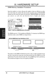
DRAM SIMM modules have a higher pin density. 20 Pins 60 Pins 88 Pins Lock P2B-F 168-Pin DIMM Memory Sockets The DIMMs must tell your retailer the correct DIMM type before purchasing. Because the number of pins are different on ... between left, center, or right to identify the type and also to prevent the wrong type from being inserted into the DIMM slot on the motherboard. This motherboard supports four clock signals per DIMM. 18 ASUS P2B-F User's Manual H/W SETUP System Memory III. HARDWARE SETUP DIMM Memory Installation Procedures: Insert the module(s) as shown.
DRAM SIMM modules have a higher pin density. 20 Pins 60 Pins 88 Pins Lock P2B-F 168-Pin DIMM Memory Sockets The DIMMs must tell your retailer the correct DIMM type before purchasing. Because the number of pins are different on ... between left, center, or right to identify the type and also to prevent the wrong type from being inserted into the DIMM slot on the motherboard. This motherboard supports four clock signals per DIMM. 18 ASUS P2B-F User's Manual H/W SETUP System Memory III. HARDWARE SETUP DIMM Memory Installation Procedures: Insert the module(s) as shown.
P2B-F User Manual
Page 19
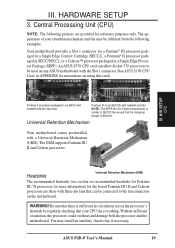
... circulation, the processor could overheat and damage both the processor and the motherboard. An ASUS S370 CPU card can be connected to the fan connectors on using this card). Central Processing Unit (CPU) NOTE: The following examples. HARDWARE SETUP 3. III. ASUS P2B-F User's Manual 19 Heatsinks Universal Retention Mechanism (URM) The recommended heatsinks (see...
... circulation, the processor could overheat and damage both the processor and the motherboard. An ASUS S370 CPU card can be connected to the fan connectors on using this card). Central Processing Unit (CPU) NOTE: The following examples. HARDWARE SETUP 3. III. ASUS P2B-F User's Manual 19 Heatsinks Universal Retention Mechanism (URM) The recommended heatsinks (see...
P2B-F User Manual
Page 21
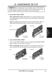
... Make sure the heatsink is firmly seated on the Slot 1 connector. H/W SETUP CPU III. You may install an auxiliary fan to fan connector ASUS P2B-F User's Manual 21 otherwise, the CPU will overheat. SECC SECC2/SEPP Push lock inward CPU fan cable to fan connector CPU fan cable to ... be outward when secured so that the lock shows through the retention mechanism's lock holes. III. HARDWARE SETUP WARNING! With the heatsink facing the motherboard's chipset, push the SECC, SECC2, or SEPP gently but firmly into the Slot 1 connector until you hear a click (the picture in step...
... Make sure the heatsink is firmly seated on the Slot 1 connector. H/W SETUP CPU III. You may install an auxiliary fan to fan connector ASUS P2B-F User's Manual 21 otherwise, the CPU will overheat. SECC SECC2/SEPP Push lock inward CPU fan cable to fan connector CPU fan cable to ... be outward when secured so that the lock shows through the retention mechanism's lock holes. III. HARDWARE SETUP WARNING! With the heatsink facing the motherboard's chipset, push the SECC, SECC2, or SEPP gently but firmly into the Slot 1 connector until you hear a click (the picture in step...
P2B-F User Manual
Page 22
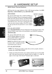
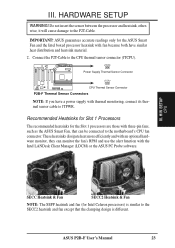
... 1 motherboard with a 2-pin thermal sensor connector. NOTE: The ASUS P2T-Cable can be used for easy FAN/CPU installation. HARDWARE SETUP ASUS Smart Thermal Solutions ASUS provides two smart solutions to your computer system. Thermal Cable CPU Fan Cable (2 black wires) (3 colored wires) To Use the ASUS S-P2FAN... (middle) or to either the upper or lower edge of the CPU heat source. Tab Sensor ← OR STICK ABOUT HERE 22 ASUS P2B-F User's Manual Attach the Heatsink on the preceding page for a Pentium® II processor packaged in an SEPP. H/W SETUP CPU III...
... 1 motherboard with a 2-pin thermal sensor connector. NOTE: The ASUS P2T-Cable can be used for easy FAN/CPU installation. HARDWARE SETUP ASUS Smart Thermal Solutions ASUS provides two smart solutions to your computer system. Thermal Cable CPU Fan Cable (2 black wires) (3 colored wires) To Use the ASUS S-P2FAN... (middle) or to either the upper or lower edge of the CPU heat source. Tab Sensor ← OR STICK ABOUT HERE 22 ASUS P2B-F User's Manual Attach the Heatsink on the preceding page for a Pentium® II processor packaged in an SEPP. H/W SETUP CPU III...
P2B-F User Manual
Page 23
..., they can be connected to the SECC2 heatsink and fan except that the clamping design is similar to the motherboard's CPU fan connector. ASUS P2B-F User's Manual 23 Connect the P2T-Cable to JTPWR. III. JTPWR Power Supply Thermal Sensor Connector JTCPU CPU Thermal Sensor... Connector P2B-F Thermal Sensor Connectors NOTE: If you have similar heat distribution and heatsink material. 2. These heatsinks dissipate heat more ...
..., they can be connected to the SECC2 heatsink and fan except that the clamping design is similar to the motherboard's CPU fan connector. ASUS P2B-F User's Manual 23 Connect the P2T-Cable to JTPWR. III. JTPWR Power Supply Thermal Sensor Connector JTCPU CPU Thermal Sensor... Connector P2B-F Thermal Sensor Connectors NOTE: If you have similar heat distribution and heatsink material. 2. These heatsinks dissipate heat more ...
P2B-F User Manual
Page 24
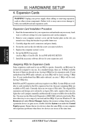
...particular device (to gain access, double-click the System icon under Device Manager displays the resource settings being used , leaving 3 IRQs free. Remove your motherboard has PCI audio onboard, an extra IRQ will experience problems when those two devices are available to cards installed in use, leaving 6 IRQs free for... Expansion Cards Some expansion cards need to use an IRQ to use at the same time. 24 ASUS P2B-F User's Manual If your computer system's cover and the bracket plate on the slot with the screw you use IRQs. Both ISA and PCI...
...particular device (to gain access, double-click the System icon under Device Manager displays the resource settings being used , leaving 3 IRQs free. Remove your motherboard has PCI audio onboard, an extra IRQ will experience problems when those two devices are available to cards installed in use, leaving 6 IRQs free for... Expansion Cards Some expansion cards need to use an IRQ to use at the same time. 24 ASUS P2B-F User's Manual If your computer system's cover and the bracket plate on the slot with the screw you use IRQs. Both ISA and PCI...
P2B-F User Manual
Page 25
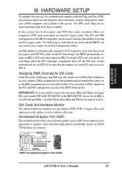
...The onboard hardware monitor uses the address 290H-297H, so legacy ISA cards must not use this motherboard are assigned automatically from those available. R P2B-F Accelerated Graphics Port (AGP) ASUS P2B-F User's Manual 25 III. If the system has both legacy and PnP, may also need... graphics cards with ultra-high memory bandwidth, such as the IRQ assignment process described earlier. HARDWARE SETUP To simplify this process, this motherboard use a DMA (Direct Memory Access) channel. DMA assignments for those used by Legacy cards. H/W SETUP DMA Channels III. For ...
...The onboard hardware monitor uses the address 290H-297H, so legacy ISA cards must not use this motherboard are assigned automatically from those available. R P2B-F Accelerated Graphics Port (AGP) ASUS P2B-F User's Manual 25 III. If the system has both legacy and PnP, may also need... graphics cards with ultra-high memory bandwidth, such as the IRQ assignment process described earlier. HARDWARE SETUP To simplify this process, this motherboard use a DMA (Direct Memory Access) channel. DMA assignments for those used by Legacy cards. H/W SETUP DMA Channels III. For ...
P2B-F User Manual
Page 26
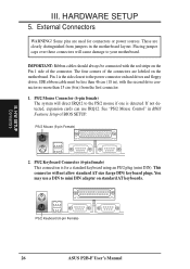
HARDWARE SETUP 5. If not detected, expansion cards can use a DIN to the power connector on the motherboard. H/W SETUP Connectors PS/2 Keyboard (6-pin Female) 26 ASUS P2B-F User's Manual III. PS/2 Mouse Connector (6-pin female) The system will cause damage to the PS/2 mouse if one is detected. You may use IRQ12. ...
HARDWARE SETUP 5. If not detected, expansion cards can use a DIN to the power connector on the motherboard. H/W SETUP Connectors PS/2 Keyboard (6-pin Female) 26 ASUS P2B-F User's Manual III. PS/2 Mouse Connector (6-pin female) The system will cause damage to the PS/2 mouse if one is detected. You may use IRQ12. ...


