P2-99 User Manual
Page 12
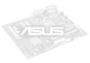
... BF1 BF0 ASUS ASIC IR IDE LED Panel Connectors Grayed items are optional at the time of the ASUS P2-99 Motherboard T: Mouse PS/2 B: Keyboard PWR_FAN CPU_FAN Parallel Port ATX Power Connector Slot 1 USB KBPWR COM1 COM2 Intel 440ZX AGPset BUS FREQ FS3 FS2 FS1 FS0 AGPFS III. DIMM Socket 1 (64/72 bit, 168 pin module) DIMM...
... BF1 BF0 ASUS ASIC IR IDE LED Panel Connectors Grayed items are optional at the time of the ASUS P2-99 Motherboard T: Mouse PS/2 B: Keyboard PWR_FAN CPU_FAN Parallel Port ATX Power Connector Slot 1 USB KBPWR COM1 COM2 Intel 440ZX AGPset BUS FREQ FS3 FS2 FS1 FS0 AGPFS III. DIMM Socket 1 (64/72 bit, 168 pin module) DIMM...
P2-99 User Manual
Page 13
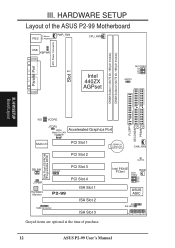
... System Warning Speaker Connector (4 pins) p. 36 System Message LED (2 pins) p. 36 System Management Interrupt Lead (2 pins) p. 36 ATX Power / Soft-Off Switch Lead (2 pins) p. 36 Reset Switch Lead (2 pins) *The optional onboard hardware monitor uses the address 290H-297H so legacy ISA cards must not use this address otherwise conflicts will occur. III. ASUS P2-99 User's Manual 13 HARDWARE...
... System Warning Speaker Connector (4 pins) p. 36 System Message LED (2 pins) p. 36 System Management Interrupt Lead (2 pins) p. 36 ATX Power / Soft-Off Switch Lead (2 pins) p. 36 Reset Switch Lead (2 pins) *The optional onboard hardware monitor uses the address 290H-297H so legacy ISA cards must not use this address otherwise conflicts will occur. III. ASUS P2-99 User's Manual 13 HARDWARE...
P2-99 User Manual
Page 31
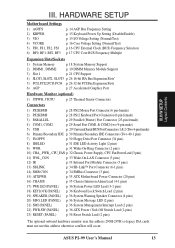
... external modems, Wake-On-Ring is set to the cabinet's IDE device activity LED. IDE Device Activity LED (2-pin IDELED) This connector supplies power to Enabled (see Power Management Setup under BIOS SETUP). H/W SETUP Connectors ASUS P2-99 User's Manual 31 The connector powers up . IDELED P2-99 P2-99 IDE Activity LED 9. IMPORTANT: This feature requires that the PWR UP On Modem Act...
... external modems, Wake-On-Ring is set to the cabinet's IDE device activity LED. IDE Device Activity LED (2-pin IDELED) This connector supplies power to Enabled (see Power Management Setup under BIOS SETUP). H/W SETUP Connectors ASUS P2-99 User's Manual 31 The connector powers up . IDELED P2-99 P2-99 IDE Activity LED 9. IMPORTANT: This feature requires that the PWR UP On Modem Act...

P2-99 User Manual
Page 36
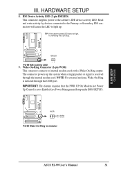
... LED P2-99 ATX Power SMI Lead Switch* * Requires an ATX power supply. H/W SETUP Connectors III. HARDWARE SETUP 17. This 2-pin connector (see the preceding figure) connects to this lead. Pushing the switch while in use. III. Pushing the button once will be used. 19. P2-99 System Panel Connections 36 ASUS P2-99 User's Manual Reset Switch Lead (2-pin RESET) This 2-pin...
... LED P2-99 ATX Power SMI Lead Switch* * Requires an ATX power supply. H/W SETUP Connectors III. HARDWARE SETUP 17. This 2-pin connector (see the preceding figure) connects to this lead. Pushing the switch while in use. III. Pushing the button once will be used. 19. P2-99 System Panel Connections 36 ASUS P2-99 User's Manual Reset Switch Lead (2-pin RESET) This 2-pin...


