User Manual
Page 6
This equipment generates, uses and can be determined by turning the equipment off and on a circuit different from digital apparatus set out in accordance with FCC regulations. WARNING: The use of shielded cables for connection of the monitor to the graphics card is no guarantee that to provide reasonable protection against harmful interference in a particular installation. VI ASUS P/I-P65UP5 User's Manual If this equipment does...
This equipment generates, uses and can be determined by turning the equipment off and on a circuit different from digital apparatus set out in accordance with FCC regulations. WARNING: The use of shielded cables for connection of the monitor to the graphics card is no guarantee that to provide reasonable protection against harmful interference in a particular installation. VI ASUS P/I-P65UP5 User's Manual If this equipment does...
User Manual
Page 8
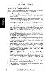
...-enabled components.) • Versatile Processor Support: Supports dual 75-200MHz Pentium or dual 150-200MHz Pentium Pro CPU card. • Versatile DRAM Memory Support: Supports eight 72-pin SIMMs of 4MB, 8MB, 16MB, 32MB, 64MB to form a memory size between 8MB to page 16.) • Super Multi-I/O: Provides two high-speed UART compatible serial ports and one easy-to-install card. (For revision compatibility information, please refer to 512MB. FEATURES (Features) II. This controller supports PIO Modes...
...-enabled components.) • Versatile Processor Support: Supports dual 75-200MHz Pentium or dual 150-200MHz Pentium Pro CPU card. • Versatile DRAM Memory Support: Supports eight 72-pin SIMMs of 4MB, 8MB, 16MB, 32MB, 64MB to form a memory size between 8MB to page 16.) • Super Multi-I/O: Provides two high-speed UART compatible serial ports and one easy-to-install card. (For revision compatibility information, please refer to 512MB. FEATURES (Features) II. This controller supports PIO Modes...

User Manual
Page 10
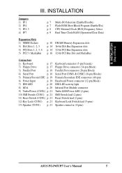
...3 PCI Slot 4 BUS Freq. CPU Card Slot SIMM Socket 8 (Bank 3) JP2 JP3 SIMM Socket 6 (Bank 2) SIMM Socket 4 (Bank 1) SIMM Socket 2 (Bank 0) PCI Slot 5 / MediaBus 2.0 ISA Slot 1 ISA Slot 2 ISA Slot 3 III. INSTALLATION (Map of the Baseboard JP4 Boot Block Progam Disable/Enable Universal Serial Bus (Reserved for future) JP1 Keyboard Serial Ports Parallel Port COM 1 COM 2 Board Power Input P9 P8 Floppy Drives Secondary IDE Primary IDE SIMM Socket 7 (Bank 3) SIMM Socket 5 (Bank 2) SIMM Socket 3 (Bank 1) SIMM Socket 1 (Bank 0) CPU Card Slot PCI Slot 1 Multi-I -P65UP5 User's Manual III...
...3 PCI Slot 4 BUS Freq. CPU Card Slot SIMM Socket 8 (Bank 3) JP2 JP3 SIMM Socket 6 (Bank 2) SIMM Socket 4 (Bank 1) SIMM Socket 2 (Bank 0) PCI Slot 5 / MediaBus 2.0 ISA Slot 1 ISA Slot 2 ISA Slot 3 III. INSTALLATION (Map of the Baseboard JP4 Boot Block Progam Disable/Enable Universal Serial Bus (Reserved for future) JP1 Keyboard Serial Ports Parallel Port COM 1 COM 2 Board Power Input P9 P8 Floppy Drives Secondary IDE Primary IDE SIMM Socket 7 (Bank 3) SIMM Socket 5 (Bank 2) SIMM Socket 3 (Bank 1) SIMM Socket 1 (Bank 0) CPU Card Slot PCI Slot 1 Multi-I -P65UP5 User's Manual III...
User Manual
Page 11
...Power connector (12-pin Block) IDE LED activity light Infrared Port Module connector Turbo LED/Power LED (2-pins) SMI Switch lead (2-pins) Reset Switch lead (2-pins) Keyboard Lock Switch lead (5-pins) Speaker connector (4-pins) ASUS P/I /O Selection (Enable/Disable) p. 7 Flash ROM Boot Block Program (Enable/Dis) p. 8 CPU External Clock (BUS) Frequency Select p. 9 Real Time Clock RAM (Operation/Clear Data) Expansion Slots 1) SIMM Sockets 3) ISA Slots 1, 2, 3 4) PCI Slots 1, 2, 3, 4 5) PCI 5 / MediaBus p. 10 DRAM Memory Expansion slots p. 14 16-bit ISA Bus Expansion slots p. 14 32-bit PCI Bus...
...Power connector (12-pin Block) IDE LED activity light Infrared Port Module connector Turbo LED/Power LED (2-pins) SMI Switch lead (2-pins) Reset Switch lead (2-pins) Keyboard Lock Switch lead (5-pins) Speaker connector (4-pins) ASUS P/I /O Selection (Enable/Disable) p. 7 Flash ROM Boot Block Program (Enable/Dis) p. 8 CPU External Clock (BUS) Frequency Select p. 9 Real Time Clock RAM (Operation/Clear Data) Expansion Slots 1) SIMM Sockets 3) ISA Slots 1, 2, 3 4) PCI Slots 1, 2, 3, 4 5) PCI 5 / MediaBus p. 10 DRAM Memory Expansion slots p. 14 16-bit ISA Bus Expansion slots p. 14 32-bit PCI Bus...
User Manual
Page 12
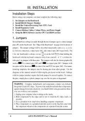
... the board. Use a grounded wrist strap before handling computer components. 4. Install DRAM Memory Modules 3. Install Expansion Cards 5. Setup the BIOS Software (see the CPU Card BIOS section) 1. See "Map of following steps: 1. facturing simplicity, the jumpers may be shown graphically such as for short (On) and for locations of jumper caps to touch the IC chips, leads, or circuitry. 3. Jumpers Several hardware settings are separated from the system. 6 ASUS P/I-P65UP5 User's Manual Unplug your computer. 1. INSTALLATION (Jumpers...
... the board. Use a grounded wrist strap before handling computer components. 4. Install DRAM Memory Modules 3. Install Expansion Cards 5. Setup the BIOS Software (see the CPU Card BIOS section) 1. See "Map of following steps: 1. facturing simplicity, the jumpers may be shown graphically such as for short (On) and for locations of jumper caps to touch the IC chips, leads, or circuitry. 3. Jumpers Several hardware settings are separated from the system. 6 ASUS P/I-P65UP5 User's Manual Unplug your computer. 1. INSTALLATION (Jumpers...
User Manual
Page 13
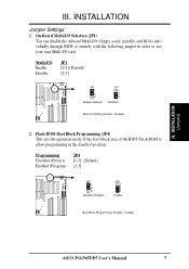
... (Disable / Enable) ASUS P/I /O card. Flash ROM Boot Block Programming (JP4) This sets the operation mode of the boot block area of the BIOS Flash ROM to allow programming in order to use your own Multi-I -P65UP5 User's Manual 7 On-Board Multi-I/O Selection (JP1) You can disable the onboard Multi-I/O (floppy, serial, parallel, and IrDA) individually through BIOS or entirely with the following jumper in the Enabled position. Multi-I/O Enable Disable JP1 [1-2] (Default) [2-3] JP1 1 2 3 Enable (Default) JP1 1 2 3 Disabled Multi I/O Setting (Enable / Disable) 2. III. INSTALLATION...
... (Disable / Enable) ASUS P/I /O card. Flash ROM Boot Block Programming (JP4) This sets the operation mode of the boot block area of the BIOS Flash ROM to allow programming in order to use your own Multi-I -P65UP5 User's Manual 7 On-Board Multi-I/O Selection (JP1) You can disable the onboard Multi-I/O (floppy, serial, parallel, and IrDA) individually through BIOS or entirely with the following jumper in the Enabled position. Multi-I/O Enable Disable JP1 [1-2] (Default) [2-3] JP1 1 2 3 Enable (Default) JP1 1 2 3 Disabled Multi I/O Setting (Enable / Disable) 2. III. INSTALLATION...
User Manual
Page 15
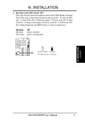
... jumper, (3) Power on the PC, (4) Turn off the PC, (5) Remove this jumper, (6) Power on the PC, (7) Hold down during bootup and enter BIOS setup to re-enter user preferences. Selections Operation Clear Data JP7 [open] (Default) [short] (momentarily) JP7 JP7 Operation (Default) Clear Data RTC RAM (Operation / Clear Data) III. Real Time Clock (RTC) RAM (JP7) This clears the user-entered information stored in the CMOS RAM of the Real Time Clock such as hard disk information and passwords. INSTALLATION 4. INSTALLATION (Jumpers) ASUS P/I-P65UP5 User's Manual...
... jumper, (3) Power on the PC, (4) Turn off the PC, (5) Remove this jumper, (6) Power on the PC, (7) Hold down during bootup and enter BIOS setup to re-enter user preferences. Selections Operation Clear Data JP7 [open] (Default) [short] (momentarily) JP7 JP7 Operation (Default) Clear Data RTC RAM (Operation / Clear Data) III. Real Time Clock (RTC) RAM (JP7) This clears the user-entered information stored in the CMOS RAM of the Real Time Clock such as hard disk information and passwords. INSTALLATION 4. INSTALLATION (Jumpers) ASUS P/I-P65UP5 User's Manual...
User Manual
Page 16
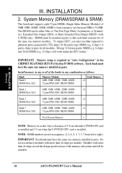
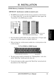
... 24 chips exceed the design specifications of 4MB, 8MB, 16MB, 32MB, 64MB to form a memory size between 8MB to right.) IMPORTANT: Each bank must be unstable. 10 ASUS P/I-P65UP5 User's Manual Each bank must use memory modules with more than 24 chips per module. System Memory (DRAM/SDRAM & SRAM) This baseboard supports eight 72-pin SIMMs (Single Inline Memory Modules) of the memory subsystem and will work minus...
... 24 chips exceed the design specifications of 4MB, 8MB, 16MB, 32MB, 64MB to form a memory size between 8MB to right.) IMPORTANT: Each bank must be unstable. 10 ASUS P/I-P65UP5 User's Manual Each bank must use memory modules with more than 24 chips per module. System Memory (DRAM/SDRAM & SRAM) This baseboard supports eight 72-pin SIMMs (Single Inline Memory Modules) of the memory subsystem and will work minus...
User Manual
Page 17
... of the SIMM memory modules. 2468 1357 III. ASUS P/I-P65UP5 User's Manual 11 III. INSTALLATION (DRAM Memory) B0 B1 B2 B3 B0 B1 B2 B3 72 Pin SIMM DRAM Sockets & Module Notched End B=Bank 2. The SIMM memory modules will only fit in symmetric pairs. 1. With your finger tips, rock the memory module into a vertical position so that it clicks into place starting from a 45...
... of the SIMM memory modules. 2468 1357 III. ASUS P/I-P65UP5 User's Manual 11 III. INSTALLATION (DRAM Memory) B0 B1 B2 B3 B0 B1 B2 B3 72 Pin SIMM DRAM Sockets & Module Notched End B=Bank 2. The SIMM memory modules will only fit in symmetric pairs. 1. With your finger tips, rock the memory module into a vertical position so that it clicks into place starting from a 45...
User Manual
Page 18
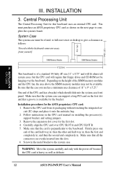
... case must purchase an ASUS proprietary CPU card as delicate. 12 ASUS P/I-P65UP5 User's Manual SIMM Memory Modules SIMM Memory Modules 9" (22.5cm) This baseboard is perpendicular to complete the system's board. Installation procedures for the first slot. 4. then the first end completely in . WARNING: Move the system carefully and only with the keyboard connector away from its packaging without touching the integrated circuit (IC) chips...
... case must purchase an ASUS proprietary CPU card as delicate. 12 ASUS P/I-P65UP5 User's Manual SIMM Memory Modules SIMM Memory Modules 9" (22.5cm) This baseboard is perpendicular to complete the system's board. Installation procedures for the first slot. 4. then the first end completely in . WARNING: Move the system carefully and only with the keyboard connector away from its packaging without touching the integrated circuit (IC) chips...
User Manual
Page 20
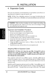
... be exclusively assigned to operate. Set any remaining IRQs are two types of a PCI card or a MediaBus card (optional multifunctional card) but most of them are already in PNP AND PCI SETUP) 9. Carefully align the card's connectors and press firmly. 6. Secure the card on the slot using PCI cards on your power supply when adding or removing expansion cards. Replace the computer system's cover. 8. Install the necessary software drivers for your computer system's cover...
... be exclusively assigned to operate. Set any remaining IRQs are two types of a PCI card or a MediaBus card (optional multifunctional card) but most of them are already in PNP AND PCI SETUP) 9. Carefully align the card's connectors and press firmly. 6. Secure the card on the slot using PCI cards on your power supply when adding or removing expansion cards. Replace the computer system's cover. 8. Install the necessary software drivers for your computer system's cover...
User Manual
Page 21
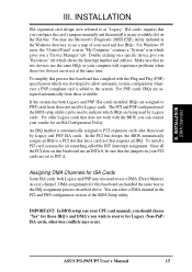
...) ISA cards, otherwise conflicts may occur. ASUS P/I-P65UP5 User's Manual 15 Since all the PCI slots on a specific device give you need to use Microsoft's Diagnostic (MSD.EXE) utility included in it in "My Computer," contains a "System" icon which was developed to allow automatic system configuration whenever a PNP-compliant card is automatically assigned to the system. IMPORTANT: In BIOS setup (see a map of the BIOS Setup utility. INSTALLATION (DMA Channels...
...) ISA cards, otherwise conflicts may occur. ASUS P/I-P65UP5 User's Manual 15 Since all the PCI slots on a specific device give you need to use Microsoft's Diagnostic (MSD.EXE) utility included in it in "My Computer," contains a "System" icon which was developed to allow automatic system configuration whenever a PNP-compliant card is automatically assigned to the system. IMPORTANT: In BIOS setup (see a map of the BIOS Setup utility. INSTALLATION (DMA Channels...
User Manual
Page 22
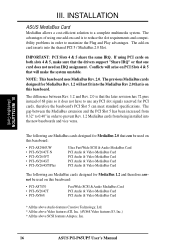
... used on this baseboard: • PCI-AS7870 • PCI-AV264CT • PCI-AV868 Fast/Wide SCSI & Audio MediaBus Card PCI Audio & Video MediaBus Card PCI Audio & Video MediaBus Card * All the above Audio features Creative Technology, Ltd. * All the above Video features ATI, Inc. (AV868 Video features S3, Inc.) * All the above SCSI features Adaptec, Inc. 16 ASUS P/I-P65UP5 User's Manual The gap between Rev. 1.2 and Rev. 2.0 is on this baseboard. IMPORTANT: PCI Slots...
... used on this baseboard: • PCI-AS7870 • PCI-AV264CT • PCI-AV868 Fast/Wide SCSI & Audio MediaBus Card PCI Audio & Video MediaBus Card PCI Audio & Video MediaBus Card * All the above Audio features Creative Technology, Ltd. * All the above Video features ATI, Inc. (AV868 Video features S3, Inc.) * All the above SCSI features Adaptec, Inc. 16 ASUS P/I-P65UP5 User's Manual The gap between Rev. 1.2 and Rev. 2.0 is on this baseboard. IMPORTANT: PCI Slots...

User Manual
Page 23
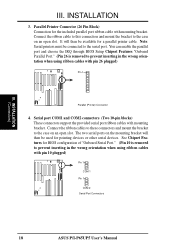
Placing jumper caps over these will cause damage to the power connector on the baseboard. Pin 1 is the side closest to your baseboard. IDE ribbon cable must be less than 6in. (15cm) from the first connector. 1. Pin 1 Floppy Drive Connector ASUS P/I-P65UP5 User's Manual 17 These are labeled on hard drives and floppy drives. Floppy drive connector (34-pin block ) This connector supports the provided floppy drive ribbon cable. The four corners of the connectors are clearly separated from Keyboard 2. May also...
Placing jumper caps over these will cause damage to the power connector on the baseboard. Pin 1 is the side closest to your baseboard. IDE ribbon cable must be less than 6in. (15cm) from the first connector. 1. Pin 1 Floppy Drive Connector ASUS P/I-P65UP5 User's Manual 17 These are labeled on hard drives and floppy drives. Floppy drive connector (34-pin block ) This connector supports the provided floppy drive ribbon cable. The four corners of the connectors are clearly separated from Keyboard 2. May also...
User Manual
Page 24
... when using ribbon cables with pin 10 plugged) Pin 1 COM 1 Pin 1 COM 2 Serial Port Connectors 18 ASUS P/I-P65UP5 User's Manual You can enable the parallel port and choose the IRQ through BIOS Setup Chipset Features "Onboard Parallel Port." (Pin 26 is removed to prevent inserting in the wrong orientation when using ribbon cables with pin 26 plugged) Pin 1 Parallel (Printer) Connector 4. INSTALLATION 3. Note: Serial printers must be connected to the case on the mounting bracket will then be used for BIOS configuration of "Onboard Serial Port." (Pin 10 is removed...
... when using ribbon cables with pin 10 plugged) Pin 1 COM 1 Pin 1 COM 2 Serial Port Connectors 18 ASUS P/I-P65UP5 User's Manual You can enable the parallel port and choose the IRQ through BIOS Setup Chipset Features "Onboard Parallel Port." (Pin 26 is removed to prevent inserting in the wrong orientation when using ribbon cables with pin 26 plugged) Pin 1 Parallel (Printer) Connector 4. INSTALLATION 3. Note: Serial printers must be connected to the case on the mounting bracket will then be used for BIOS configuration of "Onboard Serial Port." (Pin 10 is removed...
User Manual
Page 25
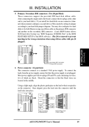
... BIOS FEATURES SETUP of which are located in the wrong orientation when using one connector (channel), then you install two hard disks on the connector. After connecting the single end to the board, connect the two plugs at the other end to your hard disk(s). Power connector (12-pin block) This connector connects to be both Masters using ribbon cables with pin 20 plugged). You may also configure two hard disks to a standard 5 Volt power supply. To connect the leads from Power Supply ASUS P/I-P65UP5 User's Manual...
... BIOS FEATURES SETUP of which are located in the wrong orientation when using one connector (channel), then you install two hard disks on the connector. After connecting the single end to the board, connect the two plugs at the other end to your hard disk(s). Power connector (12-pin block) This connector connects to be both Masters using ribbon cables with pin 20 plugged). You may also configure two hard disks to a standard 5 Volt power supply. To connect the leads from Power Supply ASUS P/I-P65UP5 User's Manual...
User Manual
Page 27
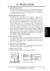
... may wish to connect the Power LED from the system case to the case-mounted speaker. Speaker connector (CON1) This 4-pin connector connects to this connector, "Suspend Switch" in the POWER MANAGEMENT SETUP of Enable (see BIOS Power Management). 11. Turbo or Power LED +5V GND SMI Lead GND Reset SW GND +5V NC Power LED & GND LOCK Keyboard Lock GND +5V GND Speaker GND Connector SPKR System Case Connections ASUS P/I-P65UP5 User's Manual 21 SMI is not in use this lead. (See...
... may wish to connect the Power LED from the system case to the case-mounted speaker. Speaker connector (CON1) This 4-pin connector connects to this connector, "Suspend Switch" in the POWER MANAGEMENT SETUP of Enable (see BIOS Power Management). 11. Turbo or Power LED +5V GND SMI Lead GND Reset SW GND +5V NC Power LED & GND LOCK Keyboard Lock GND +5V GND Speaker GND Connector SPKR System Case Connections ASUS P/I-P65UP5 User's Manual 21 SMI is not in use this lead. (See...
User Manual
Page 29
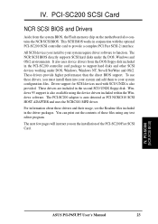
... few pages will instruct you on the motherboard also contains the NCR SCSI BIOS. PCI-SC200 (NCR SCSI BIOS) ASUS P/I-P65UP5 User's Manual 23 To use these files using the device drivers included within the Windows software. You can print out the contents of the PCI-SC200 Fast SCSI Card. It also uses device drivers from the system BIOS, the Flash memory chip on the installation of these drivers, you install to support hard disks and other SCSI devices working under the DOS...
... few pages will instruct you on the motherboard also contains the NCR SCSI BIOS. PCI-SC200 (NCR SCSI BIOS) ASUS P/I-P65UP5 User's Manual 23 To use these files using the device drivers included within the Windows software. You can print out the contents of the PCI-SC200 Fast SCSI Card. It also uses device drivers from the system BIOS, the Flash memory chip on the installation of these drivers, you install to support hard disks and other SCSI devices working under the DOS...
User Manual
Page 30
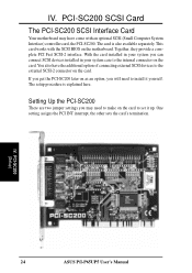
... SCSI-2 connector on the card. You also have come with the SCSI BIOS on the card to install it up. One setting assigns the PCI INT interrupt, the other sets the card's termination. IV. If you get the PCI-SC200 later on as an option, you will need to make on the motherboard. The setup procedure is also available separately. PCI-SC200 (Setup) 24 ASUS P/I-P65UP5 User's Manual Together...
... SCSI-2 connector on the card. You also have come with the SCSI BIOS on the card to install it up. One setting assigns the PCI INT interrupt, the other sets the card's termination. IV. If you get the PCI-SC200 later on as an option, you will need to make on the motherboard. The setup procedure is also available separately. PCI-SC200 (Setup) 24 ASUS P/I-P65UP5 User's Manual Together...
User Manual
Page 31
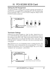
... will not work properly. External devices connect to properly assign the card's interrupt. The PCI-SC200 has "active" termination that you do it by setting jumper JP1 or JP2. Many SCSI devices use the PCI-SC200 with a fifty-pin flat ribbon cable. If you assign the INT by setting the jumper. Internal devices connect to form a "daisy chain." On the PCI-SC200, you need to change the setting to terminate...
... will not work properly. External devices connect to properly assign the card's interrupt. The PCI-SC200 has "active" termination that you do it by setting jumper JP1 or JP2. Many SCSI devices use the PCI-SC200 with a fifty-pin flat ribbon cable. If you assign the INT by setting the jumper. Internal devices connect to form a "daisy chain." On the PCI-SC200, you need to change the setting to terminate...


