User Manual
Page 1
Motherboard NCL-DS1 Series NCL-DS1 NCL-D1 NCL-DS1R1 NCL-DS1R2 NCL-D1R1
Motherboard NCL-DS1 Series NCL-DS1 NCL-D1 NCL-DS1R1 NCL-DS1R2 NCL-D1R1
User Manual
Page 3
... vi Safety information vii About this guide viii Typography ix NCL-DS1 Series specifications summary x Chapter 1: Product introduction 1.1 Welcome 1-1 1.2 Package contents 1-1 1.3 Special features 1-2 1.3.1 Product highlights 1-2 1.3.2 Innovative ASUS features 1-4 Chapter 2: Hardware information 2.1 Before you proceed 1 2.2.1 Placement direction 2 2.2.2 Screw holes 2 2.2 Motherboard overview 2 2.2.3 CEK spring support for motherboard 3 2.2.4 Motherboard layouts 6 2.2.5 Layout contents 9 2.3 Central Processing Unit (CPU 11 2.3.1 Installing...
... vi Safety information vii About this guide viii Typography ix NCL-DS1 Series specifications summary x Chapter 1: Product introduction 1.1 Welcome 1-1 1.2 Package contents 1-1 1.3 Special features 1-2 1.3.1 Product highlights 1-2 1.3.2 Innovative ASUS features 1-4 Chapter 2: Hardware information 2.1 Before you proceed 1 2.2.1 Placement direction 2 2.2.2 Screw holes 2 2.2 Motherboard overview 2 2.2.3 CEK spring support for motherboard 3 2.2.4 Motherboard layouts 6 2.2.5 Layout contents 9 2.3 Central Processing Unit (CPU 11 2.3.1 Installing...

User Manual
Page 7
... in any damage, contact your dealer immediately. • To avoid short circuits, keep paper clips, screws, and staples away from the motherboard, ensure that your power supply is broken, do not try to or from the system, ensure that came with the product, contact a... qualified service technician or your retailer. Operation safety • Before installing the motherboard and adding devices on a stable surface. • If you add a device. • Before connecting or removing signal cables from connectors, slots,...
... in any damage, contact your dealer immediately. • To avoid short circuits, keep paper clips, screws, and staples away from the motherboard, ensure that your power supply is broken, do not try to or from the system, ensure that came with the product, contact a... qualified service technician or your retailer. Operation safety • Before installing the motherboard and adding devices on a stable surface. • If you add a device. • Before connecting or removing signal cables from connectors, slots,...

User Manual
Page 8
... appendix includes additional information that you may have to change system settings through the BIOS Setup menus. ASUS websites The ASUS website provides updated information on the motherboard. • Chapter 3: Powering up This chapter describes the power up sequence and ways of the ... for additional information and for product and software updates. 1. Where to find more information Refer to the ASUS contact information. 2. Detailed descriptions of the motherboard and the new technologies it supports. • Chapter 2: Hardware information This chapter lists the hardware setup...
... appendix includes additional information that you may have to change system settings through the BIOS Setup menus. ASUS websites The ASUS website provides updated information on the motherboard. • Chapter 3: Powering up This chapter describes the power up sequence and ways of the ... for additional information and for product and software updates. 1. Where to find more information Refer to the ASUS contact information. 2. Detailed descriptions of the motherboard and the new technologies it supports. • Chapter 2: Hardware information This chapter lists the hardware setup...

User Manual
Page 13
This chapter describes the motherboard features and the new technologies it supports. 1Product introduction
This chapter describes the motherboard features and the new technologies it supports. 1Product introduction

User Manual
Page 15
... latest technologies, making it , check the items in your package with the list below. 1.2 Package contents Check your motherboard package for buying an ASUS® NCL-DS1 Series motherboard! Before you for the following items. Motherboard ASUS NCL-DS1 Series motherboard Cables 2 x Serial ATA signal cables (2-in-1) 1 x Serial ATA power cable (dual-plug) 2 x SCSI Ultra320 cables ( f o r S C S I m o d e l s o n l y ) 80-conductor...
... latest technologies, making it , check the items in your package with the list below. 1.2 Package contents Check your motherboard package for buying an ASUS® NCL-DS1 Series motherboard! Before you for the following items. Motherboard ASUS NCL-DS1 Series motherboard Cables 2 x Serial ATA signal cables (2-in-1) 1 x Serial ATA power cable (dual-plug) 2 x SCSI Ultra320 cables ( f o r S C S I m o d e l s o n l y ) 80-conductor...
User Manual
Page 16
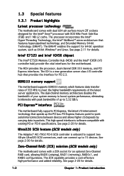
...server applications. See page 2-30 for details. 1-2 Chapter 1: Product introduction 1.3 Special features 1.3.1 Product highlights Latest processor technology The motherboard comes with dual 604-pin surface mount ZIF sockets designed for the Intel® Xeon™ processor with a ZCR socket for...Threading Technology, the Intel® NetBurst™ micro-architecture that speeds up to 5.32 GB/s. DDR333 memory support The motherboard supports DDR333 memory which features data transfer rates of your system memory to boost system performance, eliminating bottlenecks with existing PCI ...
...server applications. See page 2-30 for details. 1-2 Chapter 1: Product introduction 1.3 Special features 1.3.1 Product highlights Latest processor technology The motherboard comes with dual 604-pin surface mount ZIF sockets designed for the Intel® Xeon™ processor with a ZCR socket for...Threading Technology, the Intel® NetBurst™ micro-architecture that speeds up to 5.32 GB/s. DDR333 memory support The motherboard supports DDR333 memory which features data transfer rates of your system memory to boost system performance, eliminating bottlenecks with existing PCI ...

User Manual
Page 17
... 480 Mbps on USB 1.1 to Gigabit bandwidth. See page 2-26 for details. USB 2.0 technology The motherboard implements the Universal Serial Bus (USB) 2.0 specification, dramatically increasing the connection speed from the 12 Mbps bandwidth on USB 2.0. ASUS NCL-DS1 Series 1-3 The SATA specification allows for thinner, more flexible cables with lower pin count, reduced...
... 480 Mbps on USB 1.1 to Gigabit bandwidth. See page 2-26 for details. USB 2.0 technology The motherboard implements the Universal Serial Bus (USB) 2.0 specification, dramatically increasing the connection speed from the 12 Mbps bandwidth on USB 2.0. ASUS NCL-DS1 Series 1-3 The SATA specification allows for thinner, more flexible cables with lower pin count, reduced...

User Manual
Page 18
... Fan technology smartly adjusts the fan speeds according to the system loading to buy a replacement ROM chip. ASUS MyLogo2™ This new feature present in the motherboard allows you to restore the original BIOS data from the support CD in case when the BIOS codes and data are corrupted. This protection eliminates...
... Fan technology smartly adjusts the fan speeds according to the system loading to buy a replacement ROM chip. ASUS MyLogo2™ This new feature present in the motherboard allows you to restore the original BIOS data from the support CD in case when the BIOS codes and data are corrupted. This protection eliminates...

User Manual
Page 19
It includes description of the jumpers and connectors on the motherboard. 2 Hardware information This chapter lists the hardware setup procedures that you have to perform when installing system components.
It includes description of the jumpers and connectors on the motherboard. 2 Hardware information This chapter lists the hardware setup procedures that you have to perform when installing system components.
User Manual
Page 20
Chapter summary 2 2.1 Before you proceed 2-1 2.2 Motherboard overview 2-2 2.3 Central Processing Unit (CPU 2-11 2.4 System memory 2-15 2.5 Expansion slots 2-17 2.6 Jumpers 2-21 2.7 Connectors 2-27 ASUS NCL-DS1 Series
Chapter summary 2 2.1 Before you proceed 2-1 2.2 Motherboard overview 2-2 2.3 Central Processing Unit (CPU 2-11 2.4 System memory 2-15 2.5 Expansion slots 2-17 2.6 Jumpers 2-21 2.7 Connectors 2-27 ASUS NCL-DS1 Series

User Manual
Page 21
...e d f r o m t h e p o w e r s u p p l y . The illustration below shows the location of the following precautions before you install motherboard components or change any motherboard settings. • Unplug the power cord from the wall socket before touching any component. • Use a grounded wrist strap or touch a safely grounded...motherboard, peripherals, and/or components. Failure to do so may cause severe damage to indicate that the system is a reminder that the power supply is switched off mode. SB_PWR1 ON Standby Power OFF Powered Off NCL-DS1 Series Standby power LED ASUS NCL...
...e d f r o m t h e p o w e r s u p p l y . The illustration below shows the location of the following precautions before you install motherboard components or change any motherboard settings. • Unplug the power cord from the wall socket before touching any component. • Use a grounded wrist strap or touch a safely grounded...motherboard, peripherals, and/or components. Failure to do so may cause severe damage to indicate that the system is a reminder that the power supply is switched off mode. SB_PWR1 ON Standby Power OFF Powered Off NCL-DS1 Series Standby power LED ASUS NCL...

User Manual
Page 22
... the configuration of 11 holes. Do not overtighten the screws! Doing so can cause you physical injury and damage motherboard components! 2.2.1 Placement direction When installing the motherboard, make sure that you use an S S I E E B 3 . 5 c o m p l i a n t c h a s s i s with external ports goes to the rear... the chassis power cord before installing or removing the motherboard. Place this motherboard. Make sure to the motherboard. 2-2 Chapter 2: Hardware information To optimize its features, we highly recommend that the motherboard fits into it into the nine holes indicated by ...
... the configuration of 11 holes. Do not overtighten the screws! Doing so can cause you physical injury and damage motherboard components! 2.2.1 Placement direction When installing the motherboard, make sure that you use an S S I E E B 3 . 5 c o m p l i a n t c h a s s i s with external ports goes to the rear... the chassis power cord before installing or removing the motherboard. Place this motherboard. Make sure to the motherboard. 2-2 Chapter 2: Hardware information To optimize its features, we highly recommend that the motherboard fits into it into the nine holes indicated by ...

User Manual
Page 23
...holes. 3. Each CEK spring has four hooks to the upper CPU heatsink holes until they snap in place. ASUS NCL-DS1 Series 2-3 Locate the CPU heatsink holes on the motherboard. Press the upper spring hooks inward, then insert to match the designated holes around the CPU area. CEK ...spring Hook To install the CEK spring: 1. Position the CEK spring underneath the motherboard, then match the CEK spring hooks to the weight of the CPU heatsinks, your motherboard package comes with two CEK springs. 2.2.3 CEK spring support for CPU2 Heatsink hole 2.
...holes. 3. Each CEK spring has four hooks to the upper CPU heatsink holes until they snap in place. ASUS NCL-DS1 Series 2-3 Locate the CPU heatsink holes on the motherboard. Press the upper spring hooks inward, then insert to match the designated holes around the CPU area. CEK ...spring Hook To install the CEK spring: 1. Position the CEK spring underneath the motherboard, then match the CEK spring hooks to the weight of the CPU heatsinks, your motherboard package comes with two CEK springs. 2.2.3 CEK spring support for CPU2 Heatsink hole 2.

User Manual
Page 24
The CEK springs appear as shown when installed. 6. 4. Press the lower spring clips inward, then insert to the CPU2 heatsink holes. CEK spring screw hole Standoffs for CPU1 Standoffs for CPU2 2-4 Chapter 2: Hardware information Before installing the motherboard into the chassis, locate the standoffs that should match the eight (8) CEK spring screw holes. If you installed a second CPU, repeat steps 2 to 4 to install the CEK spring to the lower CPU heatsink holes until they snap in place. 5.
The CEK springs appear as shown when installed. 6. 4. Press the lower spring clips inward, then insert to the CPU2 heatsink holes. CEK spring screw hole Standoffs for CPU1 Standoffs for CPU2 2-4 Chapter 2: Hardware information Before installing the motherboard into the chassis, locate the standoffs that should match the eight (8) CEK spring screw holes. If you installed a second CPU, repeat steps 2 to 4 to install the CEK spring to the lower CPU heatsink holes until they snap in place. 5.

User Manual
Page 25
Socket for CPU1 Socket for illustration. ASUS NCL-DS1 Series 2-5 The CPU sockets should be right on top of their respective standoffs. otherwise, you can not install the CPU heatsinks properly. 8. Secure the motherboard with the external I/O ports toward the chassis rear panel. Refer to section "2.2.2 Screw holes" for CPU2 Make sure that the standoffs perfectly match the CEK spring screw holes; 7. Install the motherboard with nine screws.
Socket for CPU1 Socket for illustration. ASUS NCL-DS1 Series 2-5 The CPU sockets should be right on top of their respective standoffs. otherwise, you can not install the CPU heatsinks properly. 8. Secure the motherboard with the external I/O ports toward the chassis rear panel. Refer to section "2.2.2 Screw holes" for CPU2 Make sure that the standoffs perfectly match the CEK spring screw holes; 7. Install the motherboard with nine screws.

User Manual
Page 26
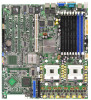
30.5cm (12in) ® NCL-DS1/NCL-D1 2.2.4 Motherboard layouts NCL-DS1 / NCL-D1 models mPGA 604 PARALLEL PORT KBPWR1 PS/2 T: Mouse B: Keyboard REAR_FAN2 USB1 USBPW12 USB2 COM1 33cm (13in) ATXPWR1 PSUSMB1 CPU_FAN1 DDR DIMM_B4 (64/72 bit, ... Intel ICH5R SATA2 SATA1 FRNT_FAN1 FRNT_FAN2 Adaptec AIC-7902W 34 68 SCSIB1 1 35 SCSIA1 • The NCL-DS1 (SCSI model for tower system) includes all the components that appear in the above layout. • The NCL-D1 (non-SCSI model for distinction. 2-6 Chapter 2: Hardware information These items are grayed out in the...
30.5cm (12in) ® NCL-DS1/NCL-D1 2.2.4 Motherboard layouts NCL-DS1 / NCL-D1 models mPGA 604 PARALLEL PORT KBPWR1 PS/2 T: Mouse B: Keyboard REAR_FAN2 USB1 USBPW12 USB2 COM1 33cm (13in) ATXPWR1 PSUSMB1 CPU_FAN1 DDR DIMM_B4 (64/72 bit, ... Intel ICH5R SATA2 SATA1 FRNT_FAN1 FRNT_FAN2 Adaptec AIC-7902W 34 68 SCSIB1 1 35 SCSIA1 • The NCL-DS1 (SCSI model for tower system) includes all the components that appear in the above layout. • The NCL-D1 (non-SCSI model for distinction. 2-6 Chapter 2: Hardware information These items are grayed out in the...
User Manual
Page 31
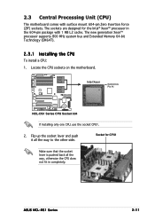
... with surface mount 604-pin Zero Insertion Force (ZIF) sockets. ASUS NCL-DS1 Series 2-11 The sockets are designed for CPU1 Make sure that the socket lever is pushed back all the way to the other side. 2.3 Central Processing Unit (CPU) The motherboard comes with 1 MB L2 cache. Socket for the Intel®...
... with surface mount 604-pin Zero Insertion Force (ZIF) sockets. ASUS NCL-DS1 Series 2-11 The sockets are designed for CPU1 Make sure that the socket lever is pushed back all the way to the other side. 2.3 Central Processing Unit (CPU) The motherboard comes with 1 MB L2 cache. Socket for the Intel®...

User Manual
Page 35
...MB, 512 MB, 1 GB, and 2 GB registered ECC DDR DIMMs into any other socket would not work. ASUS NCL-DS1 Series 2-15 Refer to the DDR Qualified Vendors List at the ASUS web site. • Due to support 184-pin DDR modules. The figure illustrates the location of the DDR ... sockets: 80 Pins 104 Pins NCL-DS1 Series 184-pin DDR DIMM sockets DIMM_B4 DIMM_A4 DIMM_B3 DIMM_A3 DIMM_B2 DIMM_A2 DIMM_B1 DIMM_A1 2.4.2 Memory configurations You may detect less than 16 GB system memory when you installed eight 2 GB DDR2 memory modules. • This motherboard does not support memory modules made...
...MB, 512 MB, 1 GB, and 2 GB registered ECC DDR DIMMs into any other socket would not work. ASUS NCL-DS1 Series 2-15 Refer to the DDR Qualified Vendors List at the ASUS web site. • Due to support 184-pin DDR modules. The figure illustrates the location of the DDR ... sockets: 80 Pins 104 Pins NCL-DS1 Series 184-pin DDR DIMM sockets DIMM_B4 DIMM_A4 DIMM_B3 DIMM_A3 DIMM_B2 DIMM_A2 DIMM_B1 DIMM_A1 2.4.2 Memory configurations You may detect less than 16 GB system memory when you installed eight 2 GB DDR2 memory modules. • This motherboard does not support memory modules made...

User Manual
Page 36
... insert the DIMM into a socket to remove a DIMM. 2 1. Remove the DIMM from the socket. 2-16 Chapter 2: Hardware information 2.4.3 Installing a DIMM Make sure to both the motherboard and the components. 1. DO NOT force a DIMM into the socket until the retaining clips snap back in only one direction. Locked Retaining Clip 2.4.4 Removing a DIMM...
... insert the DIMM into a socket to remove a DIMM. 2 1. Remove the DIMM from the socket. 2-16 Chapter 2: Hardware information 2.4.3 Installing a DIMM Make sure to both the motherboard and the components. 1. DO NOT force a DIMM into the socket until the retaining clips snap back in only one direction. Locked Retaining Clip 2.4.4 Removing a DIMM...


