
NCCH-DR User Manual English Version
Page 7
.... • If you detect any damage, contact your dealer immediately. • To avoid short circuits, keep paper clips, screws, and staples away from connectors, slots, sockets and circuitry. • Avoid dust, humidity, and temperature extremes. If you are connected. If possible, disconnect all cables are correctly connected and the power cables...
.... • If you detect any damage, contact your dealer immediately. • To avoid short circuits, keep paper clips, screws, and staples away from connectors, slots, sockets and circuitry. • Avoid dust, humidity, and temperature extremes. If you are connected. If possible, disconnect all cables are correctly connected and the power cables...

NCCH-DR User Manual English Version
Page 10
NCCH-DR Series specifications summary CPU Chipset Front Side Bus Memory Expansion slots Storage LAN USB BIOS features Rear panel Support for dual Intel® Xeon™ ...: Intel® E7210 Memory Controller Hub (MCH) South bridge: Intel® 6300ESB I/O Controller Hub (ICH) 800 MHz Dual-channel memory architecture 4 x 184-pin DDR DIMM sockets for up to 4GB memory Supports PC3200/PC2700 unbuffered ECC or non-ECC DDR DIMMs 1 x PCI-X 66 MHz/64-bit slot (supports ZCR, PCI-X 1.0) 1 x PCI...
NCCH-DR Series specifications summary CPU Chipset Front Side Bus Memory Expansion slots Storage LAN USB BIOS features Rear panel Support for dual Intel® Xeon™ ...: Intel® E7210 Memory Controller Hub (MCH) South bridge: Intel® 6300ESB I/O Controller Hub (ICH) 800 MHz Dual-channel memory architecture 4 x 184-pin DDR DIMM sockets for up to 4GB memory Supports PC3200/PC2700 unbuffered ECC or non-ECC DDR DIMMs 1 x PCI-X 66 MHz/64-bit slot (supports ZCR, PCI-X 1.0) 1 x PCI...

NCCH-DR User Manual English Version
Page 16
.... 1-2 Chapter 1: Product introduction See page 2-29 for details. 1.3 Special features 1.3.1 Product highlights Latest processor technology The motherboard comes with dual 604-pin surface mount ZIF sockets designed for the latest 3D graphics, multimedia, and Internet applications. The processor incorporates the Intel® Hyper-Threading Technology, the Intel® NetBurst™ micro...
.... 1-2 Chapter 1: Product introduction See page 2-29 for details. 1.3 Special features 1.3.1 Product highlights Latest processor technology The motherboard comes with dual 604-pin surface mount ZIF sockets designed for the latest 3D graphics, multimedia, and Internet applications. The processor incorporates the Intel® Hyper-Threading Technology, the Intel® NetBurst™ micro...

NCCH-DR User Manual English Version
Page 21
This is switched off mode. NCCH-DR NCCH-DR Onboard LED SB_PWR1 ON Standby Power OFF Powered Off ASUS NCCH-DR 2-1 Failure to do so may cause severe damage to indicate that the system is ON, in sleep mode, or in any component, ensure that the ... shows the location of the following precautions before you install motherboard components or change any motherboard settings. • Unplug the power cord from the wall socket before touching any component. • Use a grounded wrist strap or touch a safely grounded object or to a metal object, such as the power supply case, before...
This is switched off mode. NCCH-DR NCCH-DR Onboard LED SB_PWR1 ON Standby Power OFF Powered Off ASUS NCCH-DR 2-1 Failure to do so may cause severe damage to indicate that the system is ON, in sleep mode, or in any component, ensure that the ... shows the location of the following precautions before you install motherboard components or change any motherboard settings. • Unplug the power cord from the wall socket before touching any component. • Use a grounded wrist strap or touch a safely grounded object or to a metal object, such as the power supply case, before...

NCCH-DR User Manual English Version
Page 26
otherwise, you can not install the CPU heatsinks properly. 10. Refer to a nut on the support plate Make sure that the CPU heatsink holes on the motherboard perfectly match the metal nuts on top of the support plates. Secure the motherboard with the external I/O ports toward the chassis rear panel. The support plates appear as shown when installed. 9. Heatsink hole matched to section "2.2.2 Screw holes" for illustration. 2-6 Chapter 2: Hardware information Install the motherboard with 9 screws. The CPU sockets should be right on the support plates;
otherwise, you can not install the CPU heatsinks properly. 10. Refer to a nut on the support plate Make sure that the CPU heatsink holes on the motherboard perfectly match the metal nuts on top of the support plates. Secure the motherboard with the external I/O ports toward the chassis rear panel. The support plates appear as shown when installed. 9. Heatsink hole matched to section "2.2.2 Screw holes" for illustration. 2-6 Chapter 2: Hardware information Install the motherboard with 9 screws. The CPU sockets should be right on the support plates;

NCCH-DR User Manual English Version
Page 28
Install the motherboard with 9 screws. Heatsink hole matched to the CPU2 heatsink holes. Secure the motherboard with the external I/O ports toward the chassis rear panel. Repeat the process to install the second spring to the hole on top of the CEK springs. The support plates appear as shown when installed. 6. Refer to the lower CPU heatsink holes until they snap in place. 5. The CPU sockets should be right on the CEK spring 7. Press the lower spring hooks inward, then insert to section "2.2.2 Screw holes" for illustration. 2-8 Chapter 2: Hardware information 4.
Install the motherboard with 9 screws. Heatsink hole matched to the CPU2 heatsink holes. Secure the motherboard with the external I/O ports toward the chassis rear panel. Repeat the process to install the second spring to the hole on top of the CEK springs. The support plates appear as shown when installed. 6. Refer to the lower CPU heatsink holes until they snap in place. 5. The CPU sockets should be right on the CEK spring 7. Press the lower spring hooks inward, then insert to section "2.2.2 Screw holes" for illustration. 2-8 Chapter 2: Hardware information 4.
NCCH-DR User Manual English Version
Page 31
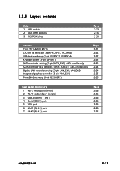
... connectors 1. LAN1 (RJ-45) port 7. 2.2.5 Layout contents Slots 1. DDR DIMM sockets 3. PS/2 keyboard port (purple) 3. Serial (COM1) port 5. USB 2.0 ports 1 and 2 4. VGA port 6. CPU sockets 2. PS/2 mouse port (green) 2. LAN2 (RJ-45) port Page 2-26 2-26 2-26 2-26 2-26 2-26 2-26 ASUS NCCH-DR 2-11 PCI/PCI-X slots Page 2-13 2-16 2-20 Jumpers Clear RTC...
... connectors 1. LAN1 (RJ-45) port 7. 2.2.5 Layout contents Slots 1. DDR DIMM sockets 3. PS/2 keyboard port (purple) 3. Serial (COM1) port 5. USB 2.0 ports 1 and 2 4. VGA port 6. CPU sockets 2. PS/2 mouse port (green) 2. LAN2 (RJ-45) port Page 2-26 2-26 2-26 2-26 2-26 2-26 2-26 ASUS NCCH-DR 2-11 PCI/PCI-X slots Page 2-13 2-16 2-20 Jumpers Clear RTC...

NCCH-DR User Manual English Version
Page 33
...ASUS NCCH-DR 2-13 Flip up the socket lever and push it all the way, otherwise the CPU does not fit in the 604-pin package with a surface mount 604-pin Zero Insertion Force (ZIF) sockets. 2.3 Central Processing Unit (CPU) The motherboard comes with 1 MB L2 cache. Intel Xeon Gold Arrow CPU2 Pin A1 CPU1 NCCH-DR NCCH-DR... CPU Socket 604 If installing only one CPU, use the socket CPU1. 2. Make sure that the socket lever is pushed back all the way to the other side. Socket for the Intel® Xeon™ processor in ...
...ASUS NCCH-DR 2-13 Flip up the socket lever and push it all the way, otherwise the CPU does not fit in the 604-pin package with a surface mount 604-pin Zero Insertion Force (ZIF) sockets. 2.3 Central Processing Unit (CPU) The motherboard comes with 1 MB L2 cache. Intel Xeon Gold Arrow CPU2 Pin A1 CPU1 NCCH-DR NCCH-DR... CPU Socket 604 If installing only one CPU, use the socket CPU1. 2. Make sure that the socket lever is pushed back all the way to the other side. Socket for the Intel® Xeon™ processor in ...

NCCH-DR User Manual English Version
Page 34
Carefully insert the CPU into the socket to secure the CPU. DO NOT force the CPU into the socket until it is locked. 6. The CPU fits only in place. The lever clicks on the side tab to indicate that it fits in one correct ...orientation. This thermal grease should come with the CPU package. 7. Carefully push down the socket lever to prevent bending the pins and damaging the CPU! 5. Position the CPU above the socket as shown. 4. Apply the thermal interface material (thermal grease) to install a second CPU. Marked corner (gold arrow...
Carefully insert the CPU into the socket to secure the CPU. DO NOT force the CPU into the socket until it is locked. 6. The CPU fits only in place. The lever clicks on the side tab to indicate that it fits in one correct ...orientation. This thermal grease should come with the CPU package. 7. Carefully push down the socket lever to prevent bending the pins and damaging the CPU! 5. Position the CPU above the socket as shown. 4. Apply the thermal interface material (thermal grease) to install a second CPU. Marked corner (gold arrow...

NCCH-DR User Manual English Version
Page 36
...Table 1. • Always install DIMMs with four Double Data Rate (DDR) Dual Inline Memory Modules (DIMM) sockets. Refer to the DDR Qualified Vendors List on the the ASUS website for details. • In dual-channel configurations, install only identical (the same type and size) DDR... single-channel mode. 2-16 Chapter 2: Hardware information The following figure illustrates the location of the DDR DIMM sockets: 104 Pins 80 Pins NCCH-DR NCCH-DR 184-Pin DDR DIMM sockets DIMM_A1 DIMM_A2 DIMM_B1 DIMM_B2 2.4.2 Memory configurations You may detect less than 4 GB system memory when you obtain ...
...Table 1. • Always install DIMMs with four Double Data Rate (DDR) Dual Inline Memory Modules (DIMM) sockets. Refer to the DDR Qualified Vendors List on the the ASUS website for details. • In dual-channel configurations, install only identical (the same type and size) DDR... single-channel mode. 2-16 Chapter 2: Hardware information The following figure illustrates the location of the DDR DIMM sockets: 104 Pins 80 Pins NCCH-DR NCCH-DR 184-Pin DDR DIMM sockets DIMM_A1 DIMM_A2 DIMM_B1 DIMM_B2 2.4.2 Memory configurations You may detect less than 4 GB system memory when you obtain ...

NCCH-DR User Manual English Version
Page 37
... Populated Populated Populated * For dual-channel configuration (3), you may: • install identical DIMMs in all four sockets, or • install identical DIMMs in DIMM_A1 and DIMM_B1 (black sockets) and identical DIMMs in DIMM_A2 and DIMM_B2 (blue sockets) ASUS NCCH-DR 2-17 Populated - - - - Populated - - Table 1: Recommended memory configurations Mode Single-channel (DDR400/DDR333) Dual-channel (DDR400/DDR333...
... Populated Populated Populated * For dual-channel configuration (3), you may: • install identical DIMMs in all four sockets, or • install identical DIMMs in DIMM_A1 and DIMM_B1 (black sockets) and identical DIMMs in DIMM_A2 and DIMM_B2 (blue sockets) ASUS NCCH-DR 2-17 Populated - - - - Populated - - Table 1: Recommended memory configurations Mode Single-channel (DDR400/DDR333) Dual-channel (DDR400/DDR333...

NCCH-DR User Manual English Version
Page 38
...in place and the DIMM is keyed with a notch so that the notch on the DIMM matches the break on the socket. Align a DIMM on the socket such that it flips out with your fingers when pressing the retaining clips. Locked retaining clip 2.4.4 Removing a DIMM Follow...these steps to unlock the DIMM. Simultaneously press the retaining clips outward to remove a DIMM. 1. Unlock a DIMM socket by pressing the retaining clips outward. 2. Remove the DIMM from the socket. 2-18 Chapter 2: Hardware information Failure to do so can cause severe damage to avoid damaging the DIMM. 3. To...
...in place and the DIMM is keyed with a notch so that the notch on the DIMM matches the break on the socket. Align a DIMM on the socket such that it flips out with your fingers when pressing the retaining clips. Locked retaining clip 2.4.4 Removing a DIMM Follow...these steps to unlock the DIMM. Simultaneously press the retaining clips outward to remove a DIMM. 1. Unlock a DIMM socket by pressing the retaining clips outward. 2. Remove the DIMM from the socket. 2-18 Chapter 2: Hardware information Failure to do so can cause severe damage to avoid damaging the DIMM. 3. To...


