
MEL User Manual
Page 1
R MEL Socket 370 Motherboard USER'S MANUAL
R MEL Socket 370 Motherboard USER'S MANUAL

MEL User Manual
Page 4
...43 Chipset Features Setup 46 Details of Chipset Features Setup 46 Power Management Setup 49 Details of the ASUS MEL Motherboard 11 III. HARDWARE SETUP 12 ASUS MEL Motherboard Layout 12 Hardware Setup Steps 14 1. Expansion Cards 21 Expansion Card Installation Procedure 21 Assigning IRQs ... ISA Cards 22 ISA Cards and Hardware Monitor 22 Accelerated Graphics Port 22 5. CONTENTS I. FEATURES 8 The ASUS MEL Motherboard 8 Parts of Power Management Setup 49 4 ASUS MEL User's Manual System Memory (DIMM 17 DIMM Memory Installation 18 3. BIOS SETUP 36 Main Menu 36 Managing...
...43 Chipset Features Setup 46 Details of Chipset Features Setup 46 Power Management Setup 49 Details of the ASUS MEL Motherboard 11 III. HARDWARE SETUP 12 ASUS MEL Motherboard Layout 12 Hardware Setup Steps 14 1. Expansion Cards 21 Expansion Card Installation Procedure 21 Assigning IRQs ... ISA Cards 22 ISA Cards and Hardware Monitor 22 Accelerated Graphics Port 22 5. CONTENTS I. FEATURES 8 The ASUS MEL Motherboard 8 Parts of Power Management Setup 49 4 ASUS MEL User's Manual System Memory (DIMM 17 DIMM Memory Installation 18 3. BIOS SETUP 36 Main Menu 36 Managing...
MEL User Manual
Page 6
... comply with FCC Rules Part 15. Without sufficient circulation, the processor could overheat and damage both the processor and the motherboard. This equipment generates, uses and can be determined by turning the equipment off and on a circuit different from that your...cause undesired operation. Be sure that there is sufficient air circulation across the processor's heatsink by one or more of Communications. 6 ASUS MEL User's Manual WARNING! This equipment has been tested and found to provide reasonable protection against harmful interference in a particular installation. ...
... comply with FCC Rules Part 15. Without sufficient circulation, the processor could overheat and damage both the processor and the motherboard. This equipment generates, uses and can be determined by turning the equipment off and on a circuit different from that your...cause undesired operation. Be sure that there is sufficient air circulation across the processor's heatsink by one or more of Communications. 6 ASUS MEL User's Manual WARNING! This equipment has been tested and found to provide reasonable protection against harmful interference in a particular installation. ...

MEL User Manual
Page 7
...BIOS software V. INTRODUCTION Sections/Checklist I . BIOS Setup Instructions on setting up the motherboard IV. If you discover damaged or missing items, please contact your retailer. (1) ASUS Motherboard (1) IDE ribbon cable for master and slave drives (1) Ribbon cable for the ... disk drives (1) Bag of spare jumper caps (1) Support CD with drivers and utilities (1) This Motherboard User's Manual ASUS IrDA-compliant infrared module (optional) ASUS CIDB chassis intrusion sensor module (optional) ASUS PCI-L101 Wake-On-LAN 10/100 Fast Ethernet Card (optional) ASUS MEL User's Manual 7 I.
...BIOS software V. INTRODUCTION Sections/Checklist I . BIOS Setup Instructions on setting up the motherboard IV. If you discover damaged or missing items, please contact your retailer. (1) ASUS Motherboard (1) IDE ribbon cable for master and slave drives (1) Ribbon cable for the ... disk drives (1) Bag of spare jumper caps (1) Support CD with drivers and utilities (1) This Motherboard User's Manual ASUS IrDA-compliant infrared module (optional) ASUS CIDB chassis intrusion sensor module (optional) ASUS PCI-L101 Wake-On-LAN 10/100 Fast Ethernet Card (optional) ASUS MEL User's Manual 7 I.

MEL User Manual
Page 8
... Enhanced ACPI & Anti-Boot Virus BIOS: Programmable BIOS (Flash EEPROM), offering enhanced ACPI for Windows 98 compatibility, built-in a small package. II. FEATURES The ASUS MEL Motherboard The ASUS MEL motherboard is carefully designed for virtually automatic setup. • Versatile Memory: Equipped with BIOS that supports autodetection of hard drives, PS/2 mouse, and Plug and Play.... • IrDA: Supports an optional infrared port module for wireless interface. • Quick Adjustments: Easy-to make changing CPU and onboard features settings a snap. 8 ASUS MEL User's Manual
... Enhanced ACPI & Anti-Boot Virus BIOS: Programmable BIOS (Flash EEPROM), offering enhanced ACPI for Windows 98 compatibility, built-in a small package. II. FEATURES The ASUS MEL Motherboard The ASUS MEL motherboard is carefully designed for virtually automatic setup. • Versatile Memory: Equipped with BIOS that supports autodetection of hard drives, PS/2 mouse, and Plug and Play.... • IrDA: Supports an optional infrared port module for wireless interface. • Quick Adjustments: Easy-to make changing CPU and onboard features settings a snap. 8 ASUS MEL User's Manual
MEL User Manual
Page 9
...and Play compatibility and power management for configuring and managing all ASUS smart series motherboards. With these features implemented in the OS, PCs can handle rates up to 33MB/sec. The best of all the energy saving standards. ASUS MEL User's Manual 9 FEATURES Performance • ACPI Ready: ACPI... PC'98 compliancy. ACPI provides more Energy Saving Features for Windows 95/98/NT. • SDRAM Optimized Performance: ASUS smart series motherboards support the new generation memory, Synchronous Dynamic Random Access Memory (SDRAM), which increases the data transfer rate to CPU. ...
...and Play compatibility and power management for configuring and managing all ASUS smart series motherboards. With these features implemented in the OS, PCs can handle rates up to 33MB/sec. The best of all the energy saving standards. ASUS MEL User's Manual 9 FEATURES Performance • ACPI Ready: ACPI... PC'98 compliancy. ACPI provides more Energy Saving Features for Windows 95/98/NT. • SDRAM Optimized Performance: ASUS smart series motherboards support the new generation memory, Synchronous Dynamic Random Access Memory (SDRAM), which increases the data transfer rate to CPU. ...
MEL User Manual
Page 10
...power supply, and system fans can be powered on by pressing the space bar on remotely through LDCM and the optional ASUS CIDB chassis intrusion sensor module. 10 ASUS MEL User's Manual Suggestions will give the user information on -hand, any user can be turned on the keyboard. &#...modem): This allows a computer to prevent possible application crashes. All the fans are set for more memory and hard drive space to critical motherboard components. A simple glimpse provides useful information to the user. • Keyboard Power Up: Keyboard Power Up can determine the stage the ...
...power supply, and system fans can be powered on by pressing the space bar on remotely through LDCM and the optional ASUS CIDB chassis intrusion sensor module. 10 ASUS MEL User's Manual Suggestions will give the user information on -hand, any user can be turned on the keyboard. &#...modem): This allows a computer to prevent possible application crashes. All the fans are set for more memory and hard drive space to critical motherboard components. A simple glimpse provides useful information to the user. • Keyboard Power Up: Keyboard Power Up can determine the stage the ...
MEL User Manual
Page 11
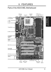
FEATURES Parts of the ASUS MEL Motherboard T: PS/2 Mouse B: PS/2 Keyboard T: USB 1 B: USB 2 B: COM 1 T: Parallel/Printer B: COM 2 T: Joystick/Midi B: Out/In/Mic (optional) ESS Solo-1 Audio (optional) AGP Port Multi-I/O Chip Programmable Flash EEPROM 5 PCI Slots Hardware Monitor (optional) 2 ISA Slots ATX Power Connector Socket 370 Intel 440LX AGPset 4 DIMM Sockets IDE 1 & 2 SB-LinkTM Wake-On-LAN Connector Connector Intel PIIX4 PCIset Wake-On-Ring DIP Connector Switches ASUS MEL User's Manual 11 II. FEATURES Motherboard Parts II.
FEATURES Parts of the ASUS MEL Motherboard T: PS/2 Mouse B: PS/2 Keyboard T: USB 1 B: USB 2 B: COM 1 T: Parallel/Printer B: COM 2 T: Joystick/Midi B: Out/In/Mic (optional) ESS Solo-1 Audio (optional) AGP Port Multi-I/O Chip Programmable Flash EEPROM 5 PCI Slots Hardware Monitor (optional) 2 ISA Slots ATX Power Connector Socket 370 Intel 440LX AGPset 4 DIMM Sockets IDE 1 & 2 SB-LinkTM Wake-On-LAN Connector Connector Intel PIIX4 PCIset Wake-On-Ring DIP Connector Switches ASUS MEL User's Manual 11 II. FEATURES Motherboard Parts II.

MEL User Manual
Page 12
HARDWARE SETUP ASUS MEL Motherboard Layout PS/2 T: Mouse B: Keyboard USB T: Port 1 B: Port 2 Socket 370 Thermal Sensor CPU_FAN COM1 JTPWR PWR_FAN SECONDARY IDE DIMM Socket...72 bit, 168 pin module) DIMM Socket 4 (64/72 bit, 168 pin module) PARALLEL PORT KBPWR ATX Power Connector PRIMARY IDE III. H/W SETUP Motherboard Layout Intel CLRTC 440LX COM2 AGPset AUX CD2 CD1 Out Line In Line GAME/AUDIO In Mic MODEM REQ5 GNT5 ESS Audio Chipset Row 1 0 3 2... Power IR IDE LED ISA Slot 2 PANEL (Grayed items are optional at the time of purchase.) 12 ASUS MEL User's Manual III.
HARDWARE SETUP ASUS MEL Motherboard Layout PS/2 T: Mouse B: Keyboard USB T: Port 1 B: Port 2 Socket 370 Thermal Sensor CPU_FAN COM1 JTPWR PWR_FAN SECONDARY IDE DIMM Socket...72 bit, 168 pin module) DIMM Socket 4 (64/72 bit, 168 pin module) PARALLEL PORT KBPWR ATX Power Connector PRIMARY IDE III. H/W SETUP Motherboard Layout Intel CLRTC 440LX COM2 AGPset AUX CD2 CD1 Out Line In Line GAME/AUDIO In Mic MODEM REQ5 GNT5 ESS Audio Chipset Row 1 0 3 2... Power IR IDE LED ISA Slot 2 PANEL (Grayed items are optional at the time of purchase.) 12 ASUS MEL User's Manual III.

MEL User Manual
Page 13
HARDWARE SETUP Motherboard Settings 1) KBPWR 2) DIP5, REQ5, GNT5 3) DIP6 4) DIP1,2,3 5) DIP7,8,9,10 p. 14 Keyboard Power Up (Enable/Disable) p. 15 Onboard Audio Settings p. 15 VIO Setting p. 16 CPU Bus ... Sensor Lead (4-1 pins) *The onboard hardware monitor uses the address 290H-297H so legacy ISA cards must not use this address; H/W SETUP Layout Contents III. ASUS MEL User's Manual 13 otherwise, conflicts will occur. III.
HARDWARE SETUP Motherboard Settings 1) KBPWR 2) DIP5, REQ5, GNT5 3) DIP6 4) DIP1,2,3 5) DIP7,8,9,10 p. 14 Keyboard Power Up (Enable/Disable) p. 15 Onboard Audio Settings p. 15 VIO Setting p. 16 CPU Bus ... Sensor Lead (4-1 pins) *The onboard hardware monitor uses the address 290H-297H so legacy ISA cards must not use this address; H/W SETUP Layout Contents III. ASUS MEL User's Manual 13 otherwise, conflicts will occur. III.

MEL User Manual
Page 14
...Setup the BIOS Software 1. Motherboard Settings WARNING! Computer motherboards, baseboards and components, such as the power supply case. 3. Hold components by pressing the spacebar) to Enable and if you do not have one, touch both of your computer. KBPWR 3 2 1 Disable (Default) KBPWR 3 2 1 Enable MEL Keyboard Power Up 14 ASUS MEL User's Manual HARDWARE SETUP ...object, such as SCSI cards, contain very delicate Integrated Circuit (IC) chips. Place components on a grounded antistatic pad or on the +5VSB lead. H/W SETUP Motherboard Settings III. Install Expansion Cards 5. Check...
...Setup the BIOS Software 1. Motherboard Settings WARNING! Computer motherboards, baseboards and components, such as the power supply case. 3. Hold components by pressing the spacebar) to Enable and if you do not have one, touch both of your computer. KBPWR 3 2 1 Disable (Default) KBPWR 3 2 1 Enable MEL Keyboard Power Up 14 ASUS MEL User's Manual HARDWARE SETUP ...object, such as SCSI cards, contain very delicate Integrated Circuit (IC) chips. Place components on a grounded antistatic pad or on the +5VSB lead. H/W SETUP Motherboard Settings III. Install Expansion Cards 5. Check...

MEL User Manual
Page 15
The example below shows all the switches in the OFF position. HARDWARE SETUP Motherboard Feature Settings (DIP Switches) The motherboard's onboard features can be adjusted through the DIP switches. REQ5 GNT5 REQ5 GNT5 III. OFF ON H/W SETUP DIP Switches ON 1 2 3 4 5 6 7 8 9 10 III. The white block represents the switch's position.
The example below shows all the switches in the OFF position. HARDWARE SETUP Motherboard Feature Settings (DIP Switches) The motherboard's onboard features can be adjusted through the DIP switches. REQ5 GNT5 REQ5 GNT5 III. OFF ON H/W SETUP DIP Switches ON 1 2 3 4 5 6 7 8 9 10 III. The white block represents the switch's position.

MEL User Manual
Page 17
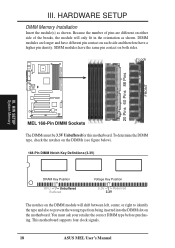
... (ECC) feature, you must have 18 chips or less. tended Data Output) chips. • BIOS shows SDRAM memory on the motherboard. Memory modules with higher pin density than 18 chips exceed specifications and may cause unstable operation. III. System Memory (DIMM) NOTE: No... chips per side (standard 8 chips/side + 1 parity chip) and make the proper settings in BIOS SETUP. III. ASUS MEL User's Manual 17 Memory modules must use a DIMM module with memory chips) of either 8, 16, 32, 64, 128MB, or 256MB. This motherboard uses only Dual Inline Memory Modules (DIMMs).
... (ECC) feature, you must have 18 chips or less. tended Data Output) chips. • BIOS shows SDRAM memory on the motherboard. Memory modules with higher pin density than 18 chips exceed specifications and may cause unstable operation. III. System Memory (DIMM) NOTE: No... chips per side (standard 8 chips/side + 1 parity chip) and make the proper settings in BIOS SETUP. III. ASUS MEL User's Manual 17 Memory modules must use a DIMM module with memory chips) of either 8, 16, 32, 64, 128MB, or 256MB. This motherboard uses only Dual Inline Memory Modules (DIMMs).
MEL User Manual
Page 18
... are longer and have different pin contact on each side and therefore have the same pin contact on the motherboard. This motherboard supports four clock signals. 18 ASUS MEL User's Manual SIMM modules have a higher pin density. HARDWARE SETUP DIMM Memory Installation Insert the module(s) as... shown. You must be 3.3V Unbuffered for this motherboard. H/W SETUP System Memory MEL 168-Pin DIMM Sockets The DIMMs must ask your ...
... are longer and have different pin contact on each side and therefore have the same pin contact on the motherboard. This motherboard supports four clock signals. 18 ASUS MEL User's Manual SIMM modules have a higher pin density. HARDWARE SETUP DIMM Memory Installation Insert the module(s) as... shown. You must be 3.3V Unbuffered for this motherboard. H/W SETUP System Memory MEL 168-Pin DIMM Sockets The DIMMs must ask your ...
MEL User Manual
Page 19
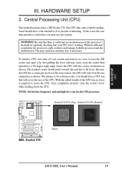
...HARDWARE SETUP 3. Without sufficient circulation, the processor could overheat and damage both the processor and the motherboard. Central Processing Unit (CPU) The motherboard provides a ZIF Socket 370. Be sure that came with the correct orientation as shown. The ...MEL Socket 370 Notch ASUS MEL User's Manual 19 The CPU that there is required to prevent overheating. With the added weight of the lever. III. If this is for your system and remove its cover. WARNING! Locate the ZIF socket and open it to insert the CPU. Insert the CPU with the motherboard...
...HARDWARE SETUP 3. Without sufficient circulation, the processor could overheat and damage both the processor and the motherboard. Central Processing Unit (CPU) The motherboard provides a ZIF Socket 370. Be sure that came with the correct orientation as shown. The ...MEL Socket 370 Notch ASUS MEL User's Manual 19 The CPU that there is required to prevent overheating. With the added weight of the lever. III. If this is for your system and remove its cover. WARNING! Locate the ZIF socket and open it to insert the CPU. Insert the CPU with the motherboard...

MEL User Manual
Page 21
... cards, requires that you intend to both your motherboard has PCI audio onboard, 1 extra IRQ will be exclusively assigned to cards installed in use Windows 95, the Resources tab under the Control Panel program). ASUS MEL User's Manual 21 Set up the BIOS if ...necessary (such as jumpers. 2. Expansion Cards WARNING! Replace the computer system's cover. 6. Assigning IRQs for expansion cards. If your motherboard and expansion cards. Currently, there are in...
... cards, requires that you intend to both your motherboard has PCI audio onboard, 1 extra IRQ will be exclusively assigned to cards installed in use Windows 95, the Resources tab under the Control Panel program). ASUS MEL User's Manual 21 Set up the BIOS if ...necessary (such as jumpers. 2. Expansion Cards WARNING! Replace the computer system's cover. 6. Assigning IRQs for expansion cards. If your motherboard and expansion cards. Currently, there are in...

MEL User Manual
Page 22
... from those used by Legacy and PNP ISA cards. Accelerated Graphics Port This motherboard provides an accelerated graphics port (AGP) slot to INT A. DMA assignments for an ISA Configuration Utility. H/W SETUP Expansion Cards MEL Accelerated Graphics Port (AGP) 22 ASUS MEL User's Manual III. HARDWARE SETUP To simplify this process this address or else...
... from those used by Legacy and PNP ISA cards. Accelerated Graphics Port This motherboard provides an accelerated graphics port (AGP) slot to INT A. DMA assignments for an ISA Configuration Utility. H/W SETUP Expansion Cards MEL Accelerated Graphics Port (AGP) 22 ASUS MEL User's Manual III. HARDWARE SETUP To simplify this process this address or else...

MEL User Manual
Page 23
... of the connectors are clearly distinguished from the first connector. 1. You may use IRQ12. H/W SETUP DCMoAnnCehcatnornsels PS/2 Keyboard (6-pin Female) ASUS MEL User's Manual 23 Pin 1 is for connectors or power sources. If not detected, expansion cards can use a DIN to the PS/2...PS/2 Keyboard Connector (6-pin PS2KBMS) This connection is the side closest to your motherboard. PS/2 Mouse Connector (6-pin PS2KBMS) The system will cause damage to the power connector on the motherboard. This connector will not allow standard AT size (large DIN) keyboard plugs. The...
... of the connectors are clearly distinguished from the first connector. 1. You may use IRQ12. H/W SETUP DCMoAnnCehcatnornsels PS/2 Keyboard (6-pin Female) ASUS MEL User's Manual 23 Pin 1 is for connectors or power sources. If not detected, expansion cards can use a DIN to the PS/2...PS/2 Keyboard Connector (6-pin PS2KBMS) This connection is the side closest to your motherboard. PS/2 Mouse Connector (6-pin PS2KBMS) The system will cause damage to the power connector on the motherboard. This connector will not allow standard AT size (large DIN) keyboard plugs. The...
MEL User Manual
Page 27
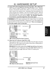
... should be used . Rotation +12V GND III. Connect the fan's plug to LAN cards with a Wake-On-LAN output, such as the ASUS PCI-L101. The CPU and/or motherboard will overheat if there is set to Enabled (see Power Management Setup under BIOS SETUP) and that the heat sink fins allow... powers up the system when a wakeup packet or signal is to the motherboard and/or the CPU fan if these pins. Orientate the fans so that your system has an ATX power supply with at least 720mA +5-volt standby power ASUS MEL User's Manual 27 Power Supply Fan CPU Fan Power GND +12V...
... should be used . Rotation +12V GND III. Connect the fan's plug to LAN cards with a Wake-On-LAN output, such as the ASUS PCI-L101. The CPU and/or motherboard will overheat if there is set to Enabled (see Power Management Setup under BIOS SETUP) and that the heat sink fins allow... powers up the system when a wakeup packet or signal is to the motherboard and/or the CPU fan if these pins. Orientate the fans so that your system has an ATX power supply with at least 720mA +5-volt standby power ASUS MEL User's Manual 27 Power Supply Fan CPU Fan Power GND +12V...
MEL User Manual
Page 28
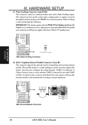
...Ring Connector (2-pin WOR) This connector connects to the pin definitions. +5V IRRX IRTX (NC) GND MEL Infrared Module Connector Front View Back View IRTX GND IRRX +5V (NC) 28 ASUS MEL User's Manual The connector powers up the system when a ringup packet or signal is detected through the ... modem card. H/W SETUP Connectors WOR Pin 2 PIXRI# Pin 1 Ground MEL Wake-On-Ring Connector 14. III. This module mounts to a small opening on the Back View and connect a ribbon cable from the module to the motherboard according to internal modem cards with a Wake-On-Ring output. NOTE: ...
...Ring Connector (2-pin WOR) This connector connects to the pin definitions. +5V IRRX IRTX (NC) GND MEL Infrared Module Connector Front View Back View IRTX GND IRRX +5V (NC) 28 ASUS MEL User's Manual The connector powers up the system when a ringup packet or signal is detected through the ... modem card. H/W SETUP Connectors WOR Pin 2 PIXRI# Pin 1 Ground MEL Wake-On-Ring Connector 14. III. This module mounts to a small opening on the Back View and connect a ribbon cable from the module to the motherboard according to internal modem cards with a Wake-On-Ring output. NOTE: ...


