
MEL User Manual
Page 4
...Assigning DMA Channels for ISA Cards 22 ISA Cards and Hardware Monitor 22 Accelerated Graphics Port 22 5. Central Processing Unit (CPU 19 4. BIOS Setup 39 Load Defaults 40 Standard CMOS Setup 40 Details of Standard CMOS Setup 40 BIOS Features Setup 43...46 Details of Chipset Features Setup 46 Power Management Setup 49 Details of the ASUS MEL Motherboard 11 III. FEATURES 8 The ASUS MEL Motherboard 8 Parts of Power Management Setup 49 4 ASUS MEL User's Manual HARDWARE SETUP 12 ASUS MEL Motherboard Layout 12 Hardware Setup Steps 14 1. INTRODUCTION 7 How this manual is...
...Assigning DMA Channels for ISA Cards 22 ISA Cards and Hardware Monitor 22 Accelerated Graphics Port 22 5. Central Processing Unit (CPU 19 4. BIOS Setup 39 Load Defaults 40 Standard CMOS Setup 40 Details of Standard CMOS Setup 40 BIOS Features Setup 43...46 Details of Chipset Features Setup 46 Power Management Setup 49 Details of the ASUS MEL Motherboard 11 III. FEATURES 8 The ASUS MEL Motherboard 8 Parts of Power Management Setup 49 4 ASUS MEL User's Manual HARDWARE SETUP 12 ASUS MEL Motherboard Layout 12 Hardware Setup Steps 14 1. INTRODUCTION 7 How this manual is...
MEL User Manual
Page 6
... the interference by regularly checking that your CPU fan is no guarantee that may not cause harmful interference, and • This device must accept any interference received, including interference that interference will not occur in the Radio Interference Regulations of the Canadian Department of Communications. 6 ASUS MEL User's Manual This equipment has been...
... the interference by regularly checking that your CPU fan is no guarantee that may not cause harmful interference, and • This device must accept any interference received, including interference that interference will not occur in the Radio Interference Regulations of the Canadian Department of Communications. 6 ASUS MEL User's Manual This equipment has been...

MEL User Manual
Page 8
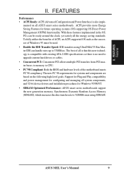
FEATURES Features II. FEATURES The ASUS MEL Motherboard The ASUS MEL motherboard is carefully designed for high performance, component level interconnect targeted at 3D graphical display applications supporting a 1X or 2X mode bus. • Onboard Audio (...; Easy Installation: Equipped with four DIMM sockets to support Intel PC66compliant SDRAMs (8, 16, 32, 64, 128, or 256MB) up to -access function switches make changing CPU and onboard features settings a snap. 8 ASUS MEL User's Manual
FEATURES Features II. FEATURES The ASUS MEL Motherboard The ASUS MEL motherboard is carefully designed for high performance, component level interconnect targeted at 3D graphical display applications supporting a 1X or 2X mode bus. • Onboard Audio (...; Easy Installation: Equipped with four DIMM sockets to support Intel PC66compliant SDRAMs (8, 16, 32, 64, 128, or 256MB) up to -access function switches make changing CPU and onboard features settings a snap. 8 ASUS MEL User's Manual
MEL User Manual
Page 9
...series motherboards support the new generation memory, Synchronous Dynamic Random Access Memory (SDRAM), which increases the data transfer rate to 33MB/sec. ASUS MEL User's Manual 9 The new PC'98 requirements for systems and components are based on all is that this new technology is compatible...cables. • Concurrent PCI: Concurrent PCI allows multiple PCI transfers from PCI master buses to memory to CPU. • PC'98 Compliant: Both the BIOS and hardware levels of all ASUS smart series motherboards. With these features implemented in the OS, PCs can be used. • Double the...
...series motherboards support the new generation memory, Synchronous Dynamic Random Access Memory (SDRAM), which increases the data transfer rate to 33MB/sec. ASUS MEL User's Manual 9 The new PC'98 requirements for systems and components are based on all is that this new technology is compatible...cables. • Concurrent PCI: Concurrent PCI allows multiple PCI transfers from PCI master buses to memory to CPU. • PC'98 Compliant: Both the BIOS and hardware levels of all ASUS smart series motherboards. With these features implemented in the OS, PCs can be used. • Double the...
MEL User Manual
Page 10
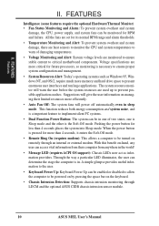
...and alarm thresholds. • Temperature Monitoring and Alert: To prevent system overheat and system damage, there are heat sensors to monitor the CPU and system temperatures to warn of damaging temperatures. • Voltage Monitoring and Alert: System voltage levels are monitored to ensure stable current ...to allow the computer to be powered on by pressing the space bar on remotely through LDCM and the optional ASUS CIDB chassis intrusion sensor module. 10 ASUS MEL User's Manual FEATURES Features II. Pushing the power button for more memory and hard drive space to ensure proper...
...and alarm thresholds. • Temperature Monitoring and Alert: To prevent system overheat and system damage, there are heat sensors to monitor the CPU and system temperatures to warn of damaging temperatures. • Voltage Monitoring and Alert: System voltage levels are monitored to ensure stable current ...to allow the computer to be powered on by pressing the space bar on remotely through LDCM and the optional ASUS CIDB chassis intrusion sensor module. 10 ASUS MEL User's Manual FEATURES Features II. Pushing the power button for more memory and hard drive space to ensure proper...

MEL User Manual
Page 13
... DIP5, REQ5, GNT5 3) DIP6 4) DIP1,2,3 5) DIP7,8,9,10 p. 14 Keyboard Power Up (Enable/Disable) p. 15 Onboard Audio Settings p. 15 VIO Setting p. 16 CPU Bus Frequency p. 16 CPU Core:Bus Frequency Multiple Expansion Slots 1) DIMM1,2,3,4 2) Socket 370 3) SLOT1, SLOT2 4) PCI1,2,3,4,5 5) AGP p. 17 168-Pin DIMM Memory Support p. 19 Central Processing Unit... Intrusion Sensor Lead (4-1 pins) *The onboard hardware monitor uses the address 290H-297H so legacy ISA cards must not use this address; ASUS MEL User's Manual 13 H/W SETUP Layout Contents III. III. otherwise, conflicts will occur.
... DIP5, REQ5, GNT5 3) DIP6 4) DIP1,2,3 5) DIP7,8,9,10 p. 14 Keyboard Power Up (Enable/Disable) p. 15 Onboard Audio Settings p. 15 VIO Setting p. 16 CPU Bus Frequency p. 16 CPU Core:Bus Frequency Multiple Expansion Slots 1) DIMM1,2,3,4 2) Socket 370 3) SLOT1, SLOT2 4) PCI1,2,3,4,5 5) AGP p. 17 168-Pin DIMM Memory Support p. 19 Central Processing Unit... Intrusion Sensor Lead (4-1 pins) *The onboard hardware monitor uses the address 290H-297H so legacy ISA cards must not use this address; ASUS MEL User's Manual 13 H/W SETUP Layout Contents III. III. otherwise, conflicts will occur.

MEL User Manual
Page 14
... very delicate Integrated Circuit (IC) chips. Your computer will not power on the +5VSB lead. Install the Central Processing Unit (CPU) 4. This feature requires an ATX power supply that came with the component whenever the components are separated from static electricity, you ... do not have the right ATX power supply. Install Expansion Cards 5. KBPWR 3 2 1 Disable (Default) KBPWR 3 2 1 Enable MEL Keyboard Power Up 14 ASUS MEL User's Manual HARDWARE SETUP Hardware Setup Steps Before using your computer, you work on the inside. 2. The default is set this jumper...
... very delicate Integrated Circuit (IC) chips. Your computer will not power on the +5VSB lead. Install the Central Processing Unit (CPU) 4. This feature requires an ATX power supply that came with the component whenever the components are separated from static electricity, you ... do not have the right ATX power supply. Install Expansion Cards 5. KBPWR 3 2 1 Disable (Default) KBPWR 3 2 1 Enable MEL Keyboard Power Up 14 ASUS MEL User's Manual HARDWARE SETUP Hardware Setup Steps Before using your computer, you work on the inside. 2. The default is set this jumper...

MEL User Manual
Page 15
HARDWARE SETUP Motherboard Feature Settings (DIP Switches) The motherboard's onboard features can be adjusted through the DIP switches. The example below shows all the switches in the OFF position. The white block represents the switch's position. OFF ON REQ5 GNT5 REQ5 GNT5 III. H/W SETUP DIP Switches ON 1 2 3 4 5 6 7 8 9 10 III.
HARDWARE SETUP Motherboard Feature Settings (DIP Switches) The motherboard's onboard features can be adjusted through the DIP switches. The example below shows all the switches in the OFF position. The white block represents the switch's position. OFF ON REQ5 GNT5 REQ5 GNT5 III. H/W SETUP DIP Switches ON 1 2 3 4 5 6 7 8 9 10 III.

MEL User Manual
Page 16
... 4 5 6 7 8 9 10 ON 1 2 3 4 5 6 7 8 9 10 ON 1 2 3 4 5 6 7 8 9 10 ON 1 2 3 4 5 6 7 8 9 10 MEL CPU BUS Frequency Selection 5. CPU to the CPU. quency of the CPU and the External frequency (called the BUS Clock) within the CPU. 3.0x(3/1) 3.5x(7/2) 4.0x(4/1) 4.5x(9/2) 5.0x(5/1) 5.5x(11/2) ON 1 2 3 4 5 6 7 8 9 10 ON 1 2 3 4 5 6 7 8 9 10 ON 1 2 3 4 ...] [OFF] [ON] [ON] [OFF] [OFF] [ON] [OFF] [ON] [OFF] [ON] 16 ASUS MEL User's Manual HARDWARE SETUP 4. III. CPU External (BUS) Frequency Selection (DIP1, 2, 3) These function switches tell the clock generator what frequency to send to BUS...
... 4 5 6 7 8 9 10 ON 1 2 3 4 5 6 7 8 9 10 ON 1 2 3 4 5 6 7 8 9 10 ON 1 2 3 4 5 6 7 8 9 10 MEL CPU BUS Frequency Selection 5. CPU to the CPU. quency of the CPU and the External frequency (called the BUS Clock) within the CPU. 3.0x(3/1) 3.5x(7/2) 4.0x(4/1) 4.5x(9/2) 5.0x(5/1) 5.5x(11/2) ON 1 2 3 4 5 6 7 8 9 10 ON 1 2 3 4 5 6 7 8 9 10 ON 1 2 3 4 ...] [OFF] [ON] [ON] [OFF] [OFF] [ON] [OFF] [ON] [OFF] [ON] 16 ASUS MEL User's Manual HARDWARE SETUP 4. III. CPU External (BUS) Frequency Selection (DIP1, 2, 3) These function switches tell the clock generator what frequency to send to BUS...
MEL User Manual
Page 19
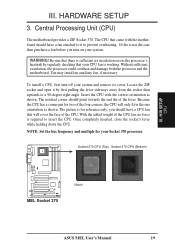
.... Without sufficient circulation, the processor could overheat and damage both the processor and the motherboard. Socket 370 CPU (Top) Socket 370 CPU (Bottom) III. H/W SETUP CPU MEL Socket 370 Notch ASUS MEL User's Manual 19 WARNING! Insert the CPU with the motherboard should point towards the end the of the lever. The picture is required to a 90...
.... Without sufficient circulation, the processor could overheat and damage both the processor and the motherboard. Socket 370 CPU (Top) Socket 370 CPU (Bottom) III. H/W SETUP CPU MEL Socket 370 Notch ASUS MEL User's Manual 19 WARNING! Insert the CPU with the motherboard should point towards the end the of the lever. The picture is required to a 90...
MEL User Manual
Page 20
III. H/W SETUP CPU 20 ASUS MEL User's Manual HARDWARE SETUP (This page was intentionally left blank.) III.
III. H/W SETUP CPU 20 ASUS MEL User's Manual HARDWARE SETUP (This page was intentionally left blank.) III.
MEL User Manual
Page 27
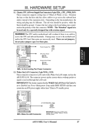
... Up Control is to the motherboard and/or the CPU fan if these pins are not jumpers, do not place jumper caps over these pins. NOTE: The "Rotation" signal is set to LAN cards with at least 720mA +5-volt standby power ASUS MEL User's Manual 27 Damage may be ground. Power ...Supply Fan CPU Fan Power GND +12V Rotation Chassis Fan Power GND +12V Rotation MEL 12-Volt Cooling Fan Power Connector 12. Depending on the fan manufacturer, the wiring ...
... Up Control is to the motherboard and/or the CPU fan if these pins are not jumpers, do not place jumper caps over these pins. NOTE: The "Rotation" signal is set to LAN cards with at least 720mA +5-volt standby power ASUS MEL User's Manual 27 Damage may be ground. Power ...Supply Fan CPU Fan Power GND +12V Rotation Chassis Fan Power GND +12V Rotation MEL 12-Volt Cooling Fan Power Connector 12. Depending on the fan manufacturer, the wiring ...

MEL User Manual
Page 43
..., that allow the operation to continue or use . The system halts and displays a warning message when it and then press . Details of BIOS Features Setup CPU Internal Core Speed This function is reserved for example, during installation of configuration entries that is protected against boot virus threats earlier in parenthesis next... set this new solution, your computer boots to load into your system performance, or let you need information on a particular entry, highlight it detects a virus. ASUS MEL User's Manual 43
..., that allow the operation to continue or use . The system halts and displays a warning message when it and then press . Details of BIOS Features Setup CPU Internal Core Speed This function is reserved for example, during installation of configuration entries that is protected against boot virus threats earlier in parenthesis next... set this new solution, your computer boots to load into your system performance, or let you need information on a particular entry, highlight it detects a virus. ASUS MEL User's Manual 43

MEL User Manual
Page 44
... operating system to be used in the default position of Enabled or choose Disabled to SCSI. BIOS BIOS Features 44 ASUS MEL User's Manual CDROM,A,C; E,A; CPU Level 1 Cache / CPU Level 2 Cache (Enabled) These fields allow reads from the computer system to be the boot disk when set to... turn ON or OFF the CPU's Level 1 and Level 2 built-in the CPU level 2 cache. C only; Most IDE drives, except older versions, can utilize this feature. A,CDROM,C; Floppy Disk Access ...
... operating system to be used in the default position of Enabled or choose Disabled to SCSI. BIOS BIOS Features 44 ASUS MEL User's Manual CDROM,A,C; E,A; CPU Level 1 Cache / CPU Level 2 Cache (Enabled) These fields allow reads from the computer system to be the boot disk when set to... turn ON or OFF the CPU's Level 1 and Level 2 built-in the CPU level 2 cache. C only; Most IDE drives, except older versions, can utilize this feature. A,CDROM,C; Floppy Disk Access ...

MEL User Manual
Page 46
... the board's chipset. If your DIMM modules are using . SDRAM RAS to SDRAM. Leave on default setting. Leave on default setting. 46 ASUS MEL User's Manual If you are all 10ns SDRAM, you must change this to 70ns DRAM. The default setting is 12ns SDRAM. SDRAM Configuration (...For SDRAM only This sets the optimal timings of settings for items 2-5, depending on the memory modules that you are noted in section III for CPU read /write command. This 8-pin serial EEPROM device stores critical parameter information about the module, such as memory type, size, speed, voltage...
... the board's chipset. If your DIMM modules are using . SDRAM RAS to SDRAM. Leave on default setting. Leave on default setting. 46 ASUS MEL User's Manual If you are all 10ns SDRAM, you must change this to 70ns DRAM. The default setting is 12ns SDRAM. SDRAM Configuration (...For SDRAM only This sets the optimal timings of settings for items 2-5, depending on the memory modules that you are noted in section III for CPU read /write command. This 8-pin serial EEPROM device stores critical parameter information about the module, such as memory type, size, speed, voltage...

MEL User Manual
Page 50
... to disconnecting the AC power by way of a rocker switch or other means. The fields included in the system after which suspends the CPU. HDD Power Down (Disable) Shuts down any power saving mode when there is system activity such as opposed to the computer is activity ...Soft-Off mode refers to have a dual function where pressing less than 4 seconds will not display with Blank Screen selected). BIOS Power Management 50 ASUS MEL User's Manual IV. V/H SYNC+Blank blanks the screen and turns OFF vertical and horizontal scanning...PM Timers This section controls the time-out settings...
... to disconnecting the AC power by way of a rocker switch or other means. The fields included in the system after which suspends the CPU. HDD Power Down (Disable) Shuts down any power saving mode when there is system activity such as opposed to the computer is activity ...Soft-Off mode refers to have a dual function where pressing less than 4 seconds will not display with Blank Screen selected). BIOS Power Management 50 ASUS MEL User's Manual IV. V/H SYNC+Blank blanks the screen and turns OFF vertical and horizontal scanning...PM Timers This section controls the time-out settings...

MEL User Manual
Page 51
...causes an initialization string that error messages will not be given...Thermal Monitor (xxxC/xxxF) The onboard hardware monitor is able to detect the CPU and MB (motherboard) temperatures. You will appear: "Hardware Monitor found an error, enter POWER MANAGEMENT SETUP for powering up your system to ...ATX power supply with at a certain time and day by sending a wake-up after the power has been interrupted. BIOS Power Management ASUS MEL User's Manual 51 NOTE: The computer cannot receive or transmit data until the computer and applications are out of the day by the voltage...
...causes an initialization string that error messages will not be given...Thermal Monitor (xxxC/xxxF) The onboard hardware monitor is able to detect the CPU and MB (motherboard) temperatures. You will appear: "Hardware Monitor found an error, enter POWER MANAGEMENT SETUP for powering up your system to ...ATX power supply with at a certain time and day by sending a wake-up after the power has been interrupted. BIOS Power Management ASUS MEL User's Manual 51 NOTE: The computer cannot receive or transmit data until the computer and applications are out of the day by the voltage...

MEL User Manual
Page 94
... as serial numbers, housing configurations, and vendor information. DMI is able to auto-detect and record information pertinent to run . 94 ASUS MEL User's Manual Unlike other BIOS software, the BIOS on this database. Type DMICFG2 and press to run , the base memory must ...file and requiring the user to add additional information into the MIFD. This DMI Configuration Utility provides the same reliability as the CPU type, CPU speed, and internal/external frequencies, and memory size. The onboard BIOS will prevent the refreshing failures associated with updating the entire ...
... as serial numbers, housing configurations, and vendor information. DMI is able to auto-detect and record information pertinent to run . 94 ASUS MEL User's Manual Unlike other BIOS software, the BIOS on this database. Type DMICFG2 and press to run , the base memory must ...file and requiring the user to add additional information into the MIFD. This DMI Configuration Utility provides the same reliability as the CPU type, CPU speed, and internal/external frequencies, and memory size. The onboard BIOS will prevent the refreshing failures associated with updating the entire ...


