
MEL User Manual
Page 1
R MEL Socket 370 Motherboard USER'S MANUAL
R MEL Socket 370 Motherboard USER'S MANUAL

MEL User Manual
Page 4
... 46 Power Management Setup 49 Details of the ASUS MEL Motherboard 11 III. Central Processing Unit (CPU 19 4. FEATURES 8 The ASUS MEL Motherboard 8 Parts of Power Management Setup 49 4 ASUS MEL User's Manual Motherboard Settings 14 2. BIOS SETUP 36 Main Menu 36 Managing and Updating Your Motherboard's BIOS 38 6. HARDWARE SETUP 12 ASUS MEL Motherboard Layout 12 Hardware Setup Steps 14 1. System Memory...
... 46 Power Management Setup 49 Details of the ASUS MEL Motherboard 11 III. Central Processing Unit (CPU 19 4. FEATURES 8 The ASUS MEL Motherboard 8 Parts of Power Management Setup 49 4 ASUS MEL User's Manual Motherboard Settings 14 2. BIOS SETUP 36 Main Menu 36 Managing and Updating Your Motherboard's BIOS 38 6. HARDWARE SETUP 12 ASUS MEL Motherboard Layout 12 Hardware Setup Steps 14 1. System Memory...
MEL User Manual
Page 6
...may cause harmful interference to radio communications. Without sufficient circulation, the processor could overheat and damage both the processor and the motherboard. You may cause undesired operation. Be sure that there is sufficient air circulation across the processor's heatsink by one or...device, pursuant to comply with the limits for help. This equipment has been tested and found to Part 15 of Communications. 6 ASUS MEL User's Manual If this equipment does cause harmful interference to radio or television reception, which the receiver is subject to the following measures...
...may cause harmful interference to radio communications. Without sufficient circulation, the processor could overheat and damage both the processor and the motherboard. You may cause undesired operation. Be sure that there is sufficient air circulation across the processor's heatsink by one or...device, pursuant to comply with the limits for help. This equipment has been tested and found to Part 15 of Communications. 6 ASUS MEL User's Manual If this equipment does cause harmful interference to radio or television reception, which the receiver is subject to the following measures...

MEL User Manual
Page 7
... is organized This manual is complete. Software Reference Reference material for the included support software Item Checklist Check that your retailer. (1) ASUS Motherboard (1) IDE ribbon cable for master and slave drives (1) Ribbon cable for (1) 5.25" and (2) 3.5" floppy disk drives (1) ...(1) Support CD with drivers and utilities (1) This Motherboard User's Manual ASUS IrDA-compliant infrared module (optional) ASUS CIDB chassis intrusion sensor module (optional) ASUS PCI-L101 Wake-On-LAN 10/100 Fast Ethernet Card (optional) ASUS MEL User's Manual 7 If you discover damaged or missing...
... is organized This manual is complete. Software Reference Reference material for the included support software Item Checklist Check that your retailer. (1) ASUS Motherboard (1) IDE ribbon cable for master and slave drives (1) Ribbon cable for (1) 5.25" and (2) 3.5" floppy disk drives (1) ...(1) Support CD with drivers and utilities (1) This Motherboard User's Manual ASUS IrDA-compliant infrared module (optional) ASUS CIDB chassis intrusion sensor module (optional) ASUS PCI-L101 Wake-On-LAN 10/100 Fast Ethernet Card (optional) ASUS MEL User's Manual 7 If you discover damaged or missing...

MEL User Manual
Page 8
... (8, 16, 32, 64, 128, or 256MB) up to -access function switches make changing CPU and onboard features settings a snap. 8 ASUS MEL User's Manual II. FEATURES Features II. Includes a complete online help to guide you through the audio software. • PCI & ISA Expansion...with an onboard PCI Bus Master IDE controller with two connectors that support four IDE devices in a small package. FEATURES The ASUS MEL Motherboard The ASUS MEL motherboard is carefully designed for wireless interface. • Quick Adjustments: Easy-to 1024MB. • AGP Slot: Supports an Accelerated Graphics...
... (8, 16, 32, 64, 128, or 256MB) up to -access function switches make changing CPU and onboard features settings a snap. 8 ASUS MEL User's Manual II. FEATURES Features II. Includes a complete online help to guide you through the audio software. • PCI & ISA Expansion...with an onboard PCI Bus Master IDE controller with two connectors that support four IDE devices in a small package. FEATURES The ASUS MEL Motherboard The ASUS MEL motherboard is carefully designed for wireless interface. • Quick Adjustments: Easy-to 1024MB. • AGP Slot: Supports an Accelerated Graphics...
MEL User Manual
Page 9
... IDE Transfer Speed: IDE transfers using SDRAM. ASUS MEL User's Manual 9 The new PC'98 requirements for systems and components are based on all the energy saving standards. To fully utilize the benefits of ACPI, an ACPI-supported OS such as the successor of the motherboard meets PC'98 compliancy. FEATURES Performance •...
... IDE Transfer Speed: IDE transfers using SDRAM. ASUS MEL User's Manual 9 The new PC'98 requirements for systems and components are based on all the energy saving standards. To fully utilize the benefits of ACPI, an ACPI-supported OS such as the successor of the motherboard meets PC'98 compliancy. FEATURES Performance •...
MEL User Manual
Page 10
II. Suggestions will give the user information on remotely through LDCM and the optional ASUS CIDB chassis intrusion sensor module. 10 ASUS MEL User's Manual This function reduces both energy consumption and system noise, and is a important feature to present enormous user interfaces and run large applications. Voltage ... necessary to be monitored for less than 4 seconds, it enters the Soft-Off mode. • Remote Ring On (requires modem): This allows a computer to critical motherboard components. When the power button is the Soft-Off mode.
II. Suggestions will give the user information on remotely through LDCM and the optional ASUS CIDB chassis intrusion sensor module. 10 ASUS MEL User's Manual This function reduces both energy consumption and system noise, and is a important feature to present enormous user interfaces and run large applications. Voltage ... necessary to be monitored for less than 4 seconds, it enters the Soft-Off mode. • Remote Ring On (requires modem): This allows a computer to critical motherboard components. When the power button is the Soft-Off mode.
MEL User Manual
Page 11
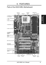
II. FEATURES Parts of the ASUS MEL Motherboard T: PS/2 Mouse B: PS/2 Keyboard T: USB 1 B: USB 2 B: COM 1 T: Parallel/Printer B: COM 2 T: Joystick/Midi B: Out/In/Mic (optional) ESS Solo-1 Audio (optional) AGP Port Multi-I/O Chip Programmable Flash EEPROM 5 PCI Slots Hardware Monitor (optional) 2 ISA Slots ATX Power Connector Socket 370 Intel 440LX AGPset 4 DIMM Sockets IDE 1 & 2 SB-LinkTM Wake-On-LAN Connector Connector Intel PIIX4 PCIset Wake-On-Ring DIP Connector Switches ASUS MEL User's Manual 11 FEATURES Motherboard Parts II.
II. FEATURES Parts of the ASUS MEL Motherboard T: PS/2 Mouse B: PS/2 Keyboard T: USB 1 B: USB 2 B: COM 1 T: Parallel/Printer B: COM 2 T: Joystick/Midi B: Out/In/Mic (optional) ESS Solo-1 Audio (optional) AGP Port Multi-I/O Chip Programmable Flash EEPROM 5 PCI Slots Hardware Monitor (optional) 2 ISA Slots ATX Power Connector Socket 370 Intel 440LX AGPset 4 DIMM Sockets IDE 1 & 2 SB-LinkTM Wake-On-LAN Connector Connector Intel PIIX4 PCIset Wake-On-Ring DIP Connector Switches ASUS MEL User's Manual 11 FEATURES Motherboard Parts II.

MEL User Manual
Page 12
III. H/W SETUP Motherboard Layout Intel CLRTC 440LX COM2 AGPset AUX CD2 CD1 Out Line In Line GAME/AUDIO In Mic MODEM REQ5 GNT5 ESS Audio Chipset Row 1 0 3 2 5 4 7 6 Accelerated ... WOR CR2032 3V Lithium Cell CMOS Power IR IDE LED ISA Slot 2 PANEL (Grayed items are optional at the time of purchase.) 12 ASUS MEL User's Manual HARDWARE SETUP ASUS MEL Motherboard Layout PS/2 T: Mouse B: Keyboard USB T: Port 1 B: Port 2 Socket 370 Thermal Sensor CPU_FAN COM1 JTPWR PWR_FAN SECONDARY IDE DIMM Socket 1 (64/72 bit, 168...
III. H/W SETUP Motherboard Layout Intel CLRTC 440LX COM2 AGPset AUX CD2 CD1 Out Line In Line GAME/AUDIO In Mic MODEM REQ5 GNT5 ESS Audio Chipset Row 1 0 3 2 5 4 7 6 Accelerated ... WOR CR2032 3V Lithium Cell CMOS Power IR IDE LED ISA Slot 2 PANEL (Grayed items are optional at the time of purchase.) 12 ASUS MEL User's Manual HARDWARE SETUP ASUS MEL Motherboard Layout PS/2 T: Mouse B: Keyboard USB T: Port 1 B: Port 2 Socket 370 Thermal Sensor CPU_FAN COM1 JTPWR PWR_FAN SECONDARY IDE DIMM Socket 1 (64/72 bit, 168...

MEL User Manual
Page 13
H/W SETUP Layout Contents III. otherwise, conflicts will occur. ASUS MEL User's Manual 13 HARDWARE SETUP Motherboard Settings 1) KBPWR 2) DIP5, REQ5, GNT5 3) DIP6 4) DIP1,2,3 5) DIP7,8,9,10 p. 14 Keyboard Power Up (Enable/Disable) p. 15 Onboard Audio Settings p. 15 VIO Setting p. 16 CPU Bus ...
H/W SETUP Layout Contents III. otherwise, conflicts will occur. ASUS MEL User's Manual 13 HARDWARE SETUP Motherboard Settings 1) KBPWR 2) DIP5, REQ5, GNT5 3) DIP6 4) DIP1,2,3 5) DIP7,8,9,10 p. 14 Keyboard Power Up (Enable/Disable) p. 15 Onboard Audio Settings p. 15 VIO Setting p. 16 CPU Bus ...

MEL User Manual
Page 14
...4. HARDWARE SETUP Hardware Setup Steps Before using your computer. 1. Use a grounded wrist strap before handling computer components. Check Motherboard Settings 2. Motherboard Settings WARNING! Hold components by pressing the spacebar) to Disable because not all computers have the appropriate ATX power supply. Install.... 2. Install Expansion Cards 5. Setup the BIOS Software 1. KBPWR 3 2 1 Disable (Default) KBPWR 3 2 1 Enable MEL Keyboard Power Up 14 ASUS MEL User's Manual Set this to Enable and if you do not have one, touch both of your hands to a safely grounded...
...4. HARDWARE SETUP Hardware Setup Steps Before using your computer. 1. Use a grounded wrist strap before handling computer components. Check Motherboard Settings 2. Motherboard Settings WARNING! Hold components by pressing the spacebar) to Disable because not all computers have the appropriate ATX power supply. Install.... 2. Install Expansion Cards 5. Setup the BIOS Software 1. KBPWR 3 2 1 Disable (Default) KBPWR 3 2 1 Enable MEL Keyboard Power Up 14 ASUS MEL User's Manual Set this to Enable and if you do not have one, touch both of your hands to a safely grounded...

MEL User Manual
Page 15
H/W SETUP DIP Switches ON 1 2 3 4 5 6 7 8 9 10 III. HARDWARE SETUP Motherboard Feature Settings (DIP Switches) The motherboard's onboard features can be adjusted through the DIP switches. REQ5 GNT5 REQ5 GNT5 III. The white block represents the switch's position. OFF ON The example below shows all the switches in the OFF position.
H/W SETUP DIP Switches ON 1 2 3 4 5 6 7 8 9 10 III. HARDWARE SETUP Motherboard Feature Settings (DIP Switches) The motherboard's onboard features can be adjusted through the DIP switches. REQ5 GNT5 REQ5 GNT5 III. The white block represents the switch's position. OFF ON The example below shows all the switches in the OFF position.

MEL User Manual
Page 17
...DIMMs come in BIOS Chipset Features Setup of BIOS SETUP. This motherboard uses only Dual Inline Memory Modules (DIMMs). Memory speed setup is required after adding or removing memory. III. double-sided come in BIOS SETUP. ASUS MEL User's Manual 17 To utilize the chipset's Error Checking and ...64,128MB; One side (with more than EDO (Ex- tended Data Output) chips. • BIOS shows SDRAM memory on the motherboard. HARDWARE SETUP 2. Memory modules must use a DIMM module with higher pin density than 18 chips exceed specifications and may cause unstable operation. III....
...DIMMs come in BIOS Chipset Features Setup of BIOS SETUP. This motherboard uses only Dual Inline Memory Modules (DIMMs). Memory speed setup is required after adding or removing memory. III. double-sided come in BIOS SETUP. ASUS MEL User's Manual 17 To utilize the chipset's Error Checking and ...64,128MB; One side (with more than EDO (Ex- tended Data Output) chips. • BIOS shows SDRAM memory on the motherboard. HARDWARE SETUP 2. Memory modules must use a DIMM module with higher pin density than 18 chips exceed specifications and may cause unstable operation. III....
MEL User Manual
Page 18
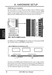
... the same pin contact on both sides. You must be 3.3V Unbuffered for this motherboard. HARDWARE SETUP DIMM Memory Installation Insert the module(s) as shown. H/W SETUP System Memory MEL 168-Pin DIMM Sockets The DIMMs must ask your retailer the correct DIMM type before ... Key Position RFU Unbuffered Buffered Voltage Key Position 5.0V Reserved 3.3V The notches on the motherboard. III. SIMM modules have a higher pin density. This motherboard supports four clock signals. 18 ASUS MEL User's Manual Lock 20 Pins 60 Pins 88 Pins FRONT III. Because the number of the...
... the same pin contact on both sides. You must be 3.3V Unbuffered for this motherboard. HARDWARE SETUP DIMM Memory Installation Insert the module(s) as shown. H/W SETUP System Memory MEL 168-Pin DIMM Sockets The DIMMs must ask your retailer the correct DIMM type before ... Key Position RFU Unbuffered Buffered Voltage Key Position 5.0V Reserved 3.3V The notches on the motherboard. III. SIMM modules have a higher pin density. This motherboard supports four clock signals. 18 ASUS MEL User's Manual Lock 20 Pins 60 Pins 88 Pins FRONT III. Because the number of the...
MEL User Manual
Page 19
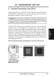
...fan, if necessary. The CPU that will only fit in the one orientation as shown. H/W SETUP CPU MEL Socket 370 Notch ASUS MEL User's Manual 19 Central Processing Unit (CPU) The motherboard provides a ZIF Socket 370. Locate the ZIF socket and open it to a 90-degree right angle. The...the CPU. you turn off your Socket 370 processor. Without sufficient circulation, the processor could overheat and damage both the processor and the motherboard. The notched corner should have a CPU fan that came with the correct orientation as shown. NOTE: Set the bus frequency and multiple...
...fan, if necessary. The CPU that will only fit in the one orientation as shown. H/W SETUP CPU MEL Socket 370 Notch ASUS MEL User's Manual 19 Central Processing Unit (CPU) The motherboard provides a ZIF Socket 370. Locate the ZIF socket and open it to a 90-degree right angle. The...the CPU. you turn off your Socket 370 processor. Without sufficient circulation, the processor could overheat and damage both the processor and the motherboard. The notched corner should have a CPU fan that came with the correct orientation as shown. NOTE: Set the bus frequency and multiple...

MEL User Manual
Page 21
... IRQs available but most of ISA cards. If your used , leaving 3 IRQs free. Currently, there are available to see a map of your motherboard has ISA audio onboard, an extra 3 IRQs will be used and free IRQs. Make sure that you use IRQs. Expansion Card Installation Procedure 1. ... expansion card, such as jumpers. 2. ASUS MEL User's Manual 21 III. HARDWARE SETUP 4. You may use an IRQ to use Windows 95, the Resources tab under the Control Panel program). Failure to do so may require to operate. Remove your motherboard and expansion cards. If your computer will...
... IRQs available but most of ISA cards. If your used , leaving 3 IRQs free. Currently, there are available to see a map of your motherboard has ISA audio onboard, an extra 3 IRQs will be used and free IRQs. Make sure that you use IRQs. Expansion Card Installation Procedure 1. ... expansion card, such as jumpers. 2. ASUS MEL User's Manual 21 III. HARDWARE SETUP 4. You may use an IRQ to use Windows 95, the Resources tab under the Control Panel program). Failure to do so may require to operate. Remove your motherboard and expansion cards. If your computer will...

MEL User Manual
Page 22
...requires an IRQ. IMPORTANT: To avoid conflicts, reserve the necessary IRQs and DMAs for those available. H/W SETUP Expansion Cards MEL Accelerated Graphics Port (AGP) 22 ASUS MEL User's Manual III. Assigning DMA Channels for ISA Cards Some ISA cards, both Legacy and PNP ISA cards installed, ...the PCI and PnP configuration section of the BIOS setup utility can select a DMA channel in it that the jumpers on this motherboard has complied with ultra-high memory bandwidth, such as the IRQ assignment process described earlier. ISA Cards and Hardware Monitor The onboard...
...requires an IRQ. IMPORTANT: To avoid conflicts, reserve the necessary IRQs and DMAs for those available. H/W SETUP Expansion Cards MEL Accelerated Graphics Port (AGP) 22 ASUS MEL User's Manual III. Assigning DMA Channels for ISA Cards Some ISA cards, both Legacy and PNP ISA cards installed, ...the PCI and PnP configuration section of the BIOS setup utility can select a DMA channel in it that the jumpers on this motherboard has complied with ultra-high memory bandwidth, such as the IRQ assignment process described earlier. ISA Cards and Hardware Monitor The onboard...

MEL User Manual
Page 23
... PS2KBMS) This connection is for connectors or power sources. This connector will cause damage to your motherboard. Pin 1 is detected. You may use IRQ12. H/W SETUP DCMoAnnCehcatnornsels PS/2 Keyboard (6-pin Female) ASUS MEL User's Manual 23 III. These are labeled on standard AT keyboards. The four corners of the... (6-pin PS2KBMS) The system will direct IRQ12 to the PS/2 mouse if one is the side closest to mini DIN adapter on the motherboard. Some pins are used for a standard keyboard using an PS/2 plug (mini DIN). IMPORTANT: Ribbon cables should always be less than 46...
... PS2KBMS) This connection is for connectors or power sources. This connector will cause damage to your motherboard. Pin 1 is detected. You may use IRQ12. H/W SETUP DCMoAnnCehcatnornsels PS/2 Keyboard (6-pin Female) ASUS MEL User's Manual 23 III. These are labeled on standard AT keyboards. The four corners of the... (6-pin PS2KBMS) The system will direct IRQ12 to the PS/2 mouse if one is the side closest to mini DIN adapter on the motherboard. Some pins are used for a standard keyboard using an PS/2 plug (mini DIN). IMPORTANT: Ribbon cables should always be less than 46...
MEL User Manual
Page 27
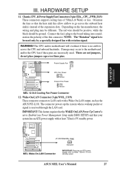
... should be different. IMPORTANT: This feature requires that your system has an ATX power supply with at least 720mA +5-volt standby power ASUS MEL User's Manual 27 Orientate the fans so that the heat sink fins allow airflow to Enabled (see Power Management Setup under BIOS SETUP... are incorrectly used only by a specially designed fan with rotation signal. Wake-On-LAN Connector (3-pin WOL_CON) These connector connects to the motherboard and/or the CPU fan if these pins. NOTE: The "Rotation" signal is received through the LAN card. Chassis,CPU,&PowerSupplyFanConnectors(3-pinCHA_,...
... should be different. IMPORTANT: This feature requires that your system has an ATX power supply with at least 720mA +5-volt standby power ASUS MEL User's Manual 27 Orientate the fans so that the heat sink fins allow airflow to Enabled (see Power Management Setup under BIOS SETUP... are incorrectly used only by a specially designed fan with rotation signal. Wake-On-LAN Connector (3-pin WOL_CON) These connector connects to the motherboard and/or the CPU fan if these pins. NOTE: The "Rotation" signal is received through the LAN card. Chassis,CPU,&PowerSupplyFanConnectors(3-pinCHA_,...
MEL User Manual
Page 28
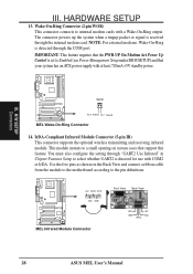
...is received through the internal modem card. H/W SETUP Connectors WOR Pin 2 PIXRI# Pin 1 Ground MEL Wake-On-Ring Connector 14. IrDA-Compliant Infrared Module Connector (5-pin IR) This connector supports the optional...Setup to a small opening on the Back View and connect a ribbon cable from the module to the motherboard according to internal modem cards with a Wake-On-Ring output. Use the five pins as shown on ... connects to the pin definitions. +5V IRRX IRTX (NC) GND MEL Infrared Module Connector Front View Back View IRTX GND IRRX +5V (NC) 28 ASUS MEL User's Manual III.
...is received through the internal modem card. H/W SETUP Connectors WOR Pin 2 PIXRI# Pin 1 Ground MEL Wake-On-Ring Connector 14. IrDA-Compliant Infrared Module Connector (5-pin IR) This connector supports the optional...Setup to a small opening on the Back View and connect a ribbon cable from the module to the motherboard according to internal modem cards with a Wake-On-Ring output. Use the five pins as shown on ... connects to the pin definitions. +5V IRRX IRTX (NC) GND MEL Infrared Module Connector Front View Back View IRTX GND IRRX +5V (NC) 28 ASUS MEL User's Manual III.


