MEL-M User Manual
Page 1
R MEL-M Socket 370 microATX Motherboard USER'S MANUAL
R MEL-M Socket 370 microATX Motherboard USER'S MANUAL
MEL-M User Manual
Page 4
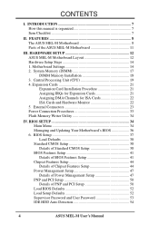
...Hardware Monitor 22 5. BIOS SETUP 34 Main Menu 34 Managing and Updating Your Motherboard's BIOS 36 6. HARDWARE SETUP 12 ASUS MEL-M Motherboard Layout 12 Hardware Setup Steps 14 1. Central Processing Unit (CPU 19 4. Motherboard Settings 14 2. INTRODUCTION 7 How this manual is organized 7 Item Checklist 7... Management Setup 47 Details of Power Management Setup 47 PNP and PCI Setup 50 Details of the ASUS MEL-M Motherboard 11 III. CONTENTS I. FEATURES 8 The ASUS MEL-M Motherboard 8 Parts of PNP and PCI Setup 50 Load BIOS Defaults 52 Load Setup Defaults 52 Supervisor ...
...Hardware Monitor 22 5. BIOS SETUP 34 Main Menu 34 Managing and Updating Your Motherboard's BIOS 36 6. HARDWARE SETUP 12 ASUS MEL-M Motherboard Layout 12 Hardware Setup Steps 14 1. Central Processing Unit (CPU 19 4. Motherboard Settings 14 2. INTRODUCTION 7 How this manual is organized 7 Item Checklist 7... Management Setup 47 Details of Power Management Setup 47 PNP and PCI Setup 50 Details of the ASUS MEL-M Motherboard 11 III. CONTENTS I. FEATURES 8 The ASUS MEL-M Motherboard 8 Parts of PNP and PCI Setup 50 Load BIOS Defaults 52 Load Setup Defaults 52 Supervisor ...

MEL-M User Manual
Page 7
...jumper caps (1) Support CD with drivers and utilities (1) This Motherboard User's Manual ASUS IrDA-compliant infrared module (optional) ASUS chassis intrusion sensor module (optional) ASUS PCI-L101 Wake-On-LAN 10/100 fast ethernet card (optional) ASUS MEL-M User's Manual 7 INTRODUCTION Sections/Checklist I . If you... discover damaged or missing items, please contact your retailer. (1) ASUS Motherboard (1) IDE ribbon cable for master and slave drives (1) Ribbon cable ...
...jumper caps (1) Support CD with drivers and utilities (1) This Motherboard User's Manual ASUS IrDA-compliant infrared module (optional) ASUS chassis intrusion sensor module (optional) ASUS PCI-L101 Wake-On-LAN 10/100 fast ethernet card (optional) ASUS MEL-M User's Manual 7 INTRODUCTION Sections/Checklist I . If you... discover damaged or missing items, please contact your retailer. (1) ASUS Motherboard (1) IDE ribbon cable for master and slave drives (1) Ribbon cable ...
MEL-M User Manual
Page 8
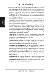
FEATURES The ASUS MEL-M Motherboard The ASUS MEL-M motherboard is carefully designed for high performance, component level interconnect targeted at 3D graphical display applications supporting a 66MHz bus. • Yamaha Audio ... (DMI): Supports DMI through BIOS, which allows hardware to communicate within a standard protocol creating a higher level of compatibility. (Requires DMI-enabled components.) 8 ASUS MEL-M User's Manual FEATURES Features II. II. Specifications • Intel Processor Support: Supports Intel's Celeron processor designed for the Socket 370 and packaged in a ...
FEATURES The ASUS MEL-M Motherboard The ASUS MEL-M motherboard is carefully designed for high performance, component level interconnect targeted at 3D graphical display applications supporting a 66MHz bus. • Yamaha Audio ... (DMI): Supports DMI through BIOS, which allows hardware to communicate within a standard protocol creating a higher level of compatibility. (Requires DMI-enabled components.) 8 ASUS MEL-M User's Manual FEATURES Features II. II. Specifications • Intel Processor Support: Supports Intel's Celeron processor designed for the Socket 370 and packaged in a ...

MEL-M User Manual
Page 9
... devices virtually automatic. • IrDA: Supports an optional infrared port module for Windows 95/98/NT.• SDRAM Optimized Performance: ASUS smart series motherboards support the new generation memory, Synchronous Dynamic Random Access Memory (SDRAM), which increases the data transfer rate to 528MB/s max using ...UltraDMA/33 Bus Master IDE can handle rates up to CPU. • PC'98 Compliant: Both the BIOS and hardware levels of motherboards. ASUS MEL-M User's Manual 9 FEATURES • Ultra DMA/33 BM IDE: Comes with an onboard PCI Bus Master IDE controller with two connectors...
... devices virtually automatic. • IrDA: Supports an optional infrared port module for Windows 95/98/NT.• SDRAM Optimized Performance: ASUS smart series motherboards support the new generation memory, Synchronous Dynamic Random Access Memory (SDRAM), which increases the data transfer rate to 528MB/s max using ...UltraDMA/33 Bus Master IDE can handle rates up to CPU. • PC'98 Compliant: Both the BIOS and hardware levels of motherboards. ASUS MEL-M User's Manual 9 FEATURES • Ultra DMA/33 BM IDE: Comes with an onboard PCI Bus Master IDE controller with two connectors...
MEL-M User Manual
Page 10
...on by pressing the space bar on managing their computer from their limited resources more memory and hard drive space to critical motherboard components. The system resource monitor will power off automatically even in . Pushing the power button for more than 4 seconds places.... When the power button is necessary to prevent possible application crashes. With this benefit on remotely through an optional ASUS CIDB module and Intel LDCM. 10 ASUS MEL-M User's Manual This function reduces both energy consumption and system noise, and is a important feature to implement silent...
...on by pressing the space bar on managing their computer from their limited resources more memory and hard drive space to critical motherboard components. The system resource monitor will power off automatically even in . Pushing the power button for more than 4 seconds places.... When the power button is necessary to prevent possible application crashes. With this benefit on remotely through an optional ASUS CIDB module and Intel LDCM. 10 ASUS MEL-M User's Manual This function reduces both energy consumption and system noise, and is a important feature to implement silent...
MEL-M User Manual
Page 11
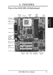
II. FEATURES Motherboard Parts II. FEATURES Parts of the ASUS MEL-M Motherboard T: PS/2 Mouse B: PS/2 Keyboard T: USB 1 B: USB 2 B: COM 1 T: Parallel/Printer B: COM 2 T: Joystick/Midi B: Out/In/Mic (optional) Yamaha Audio (optional) AGP Port 3 PCI Slots Audio Codec (optional) Multi-I/O Chip 1 ISA Slot ATX Power Connector Socket 370 Intel 440LX AGPset 3 DIMM Sockets DIP Switches Wake-On-LAN SB-LinkTM Intel PIIX4 Programmable Hardware Monitor Connector Connector PCIset Flash EEPROM (optional) ASUS MEL-M User's Manual 11
II. FEATURES Motherboard Parts II. FEATURES Parts of the ASUS MEL-M Motherboard T: PS/2 Mouse B: PS/2 Keyboard T: USB 1 B: USB 2 B: COM 1 T: Parallel/Printer B: COM 2 T: Joystick/Midi B: Out/In/Mic (optional) Yamaha Audio (optional) AGP Port 3 PCI Slots Audio Codec (optional) Multi-I/O Chip 1 ISA Slot ATX Power Connector Socket 370 Intel 440LX AGPset 3 DIMM Sockets DIP Switches Wake-On-LAN SB-LinkTM Intel PIIX4 Programmable Hardware Monitor Connector Connector PCIset Flash EEPROM (optional) ASUS MEL-M User's Manual 11
MEL-M User Manual
Page 12
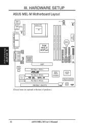
... III. HARDWARE SETUP ASUS MEL-M Motherboard Layout PS/2 T: Mouse B: Keyboard USB T: Port 1 B: Port 2 T: Top B: Bottom COM1 KBPWR Socket 370 Thermal Sensor 01 01 01 PWR_FAN CPU_FAN CHA_FAN PARALLEL PORT ATX Power ... Yamaha Audio Chipset In Mic Audio Codec AGP PCI Slot 1 (PCI1) R Multi-I/O & Keyboard Controller PCI Slot 2 (PCI2) MEL-M WOL_CON SBLINK PCI Slot 3 (PCI3) ISA Slot 1 (SLOT1) 01 23 45 IDELED Intel PIIX4 Chipset ASUS ASIC 2Mbit Flash EEPROM (Programmable BIOS) Thermal Sensor CHASIS Hardware Monitor SMB (Grayed items are optional at the...
... III. HARDWARE SETUP ASUS MEL-M Motherboard Layout PS/2 T: Mouse B: Keyboard USB T: Port 1 B: Port 2 T: Top B: Bottom COM1 KBPWR Socket 370 Thermal Sensor 01 01 01 PWR_FAN CPU_FAN CHA_FAN PARALLEL PORT ATX Power ... Yamaha Audio Chipset In Mic Audio Codec AGP PCI Slot 1 (PCI1) R Multi-I/O & Keyboard Controller PCI Slot 2 (PCI2) MEL-M WOL_CON SBLINK PCI Slot 3 (PCI3) ISA Slot 1 (SLOT1) 01 23 45 IDELED Intel PIIX4 Chipset ASUS ASIC 2Mbit Flash EEPROM (Programmable BIOS) Thermal Sensor CHASIS Hardware Monitor SMB (Grayed items are optional at the...

MEL-M User Manual
Page 13
otherwise, conflicts will occur. III. HARDWARE SETUP Motherboard Settings 1) KBPWR 2) DIP-Switch 5 3) DIP-Switch 6 4) DIP-Switch 1,2,3,4 5) DIP-Switch 7,8,9,10 p. 14 Keyboard Power Up (Enable/Disable) p. 15 Onboard Audio Setting p. 15 VIO Setting p. 16 ... (PANEL) p. 32 System Warning Speaker Connector (4 pins) *The onboard hardware monitor uses the address 290H-297H so legacy ISA cards must not use this address; ASUS MEL-M User's Manual 13 H/W SETUP Layout Contents III.
otherwise, conflicts will occur. III. HARDWARE SETUP Motherboard Settings 1) KBPWR 2) DIP-Switch 5 3) DIP-Switch 6 4) DIP-Switch 1,2,3,4 5) DIP-Switch 7,8,9,10 p. 14 Keyboard Power Up (Enable/Disable) p. 15 Onboard Audio Setting p. 15 VIO Setting p. 16 ... (PANEL) p. 32 System Warning Speaker Connector (4 pins) *The onboard hardware monitor uses the address 290H-297H so legacy ISA cards must not use this address; ASUS MEL-M User's Manual 13 H/W SETUP Layout Contents III.

MEL-M User Manual
Page 14
...or to Enable if you do not have the right ATX power supply. 01 01 01 R MEL-M MEL-M Keyboard Power Up KBPWR 3 2 1 Disable (Default) KBPWR 3 2 1 Enable 14 ASUS MEL-M User's Manual Check Motherboard Settings 2. Connect Ribbon Cables, Panel Wires, and Power Supply 6. If you wish to use ... your computer, you do not have the appropriate ATX power supply. Setup the BIOS Software 1. Install Expansion Cards 5. H/W SETUP Motherboard Settings III. HARDWARE SETUP Hardware Setup Steps Before using your computer when working on if you set to disable or enable the keyboard...
...or to Enable if you do not have the right ATX power supply. 01 01 01 R MEL-M MEL-M Keyboard Power Up KBPWR 3 2 1 Disable (Default) KBPWR 3 2 1 Enable 14 ASUS MEL-M User's Manual Check Motherboard Settings 2. Connect Ribbon Cables, Panel Wires, and Power Supply 6. If you wish to use ... your computer, you do not have the appropriate ATX power supply. Setup the BIOS Software 1. Install Expansion Cards 5. H/W SETUP Motherboard Settings III. HARDWARE SETUP Hardware Setup Steps Before using your computer when working on if you set to disable or enable the keyboard...

MEL-M User Manual
Page 15
HARDWARE SETUP Motherboard Settings (DIP Switches) Some of the motherboard's onboard functions can be adjusted through the DIP switches. The example below shows all the switches in the OFF position. R MEL-M MEL-M DIP Switches 01 01 01 ON 1 2 3 4 5 6 7 8 9 10 OFF ON The white block represents the switch's position. III.
HARDWARE SETUP Motherboard Settings (DIP Switches) Some of the motherboard's onboard functions can be adjusted through the DIP switches. The example below shows all the switches in the OFF position. R MEL-M MEL-M DIP Switches 01 01 01 ON 1 2 3 4 5 6 7 8 9 10 OFF ON The white block represents the switch's position. III.
MEL-M User Manual
Page 16
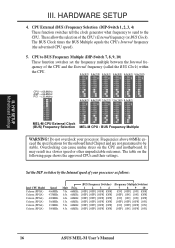
...] [OFF] [OFF] [ON] 4.5x 66MHz [OFF] [OFF] [OFF] [OFF] [OFF] [ON] [OFF] [ON] 16 ASUS MEL-M User's Manual The table on the CPU and motherboard. H/W SETUP Motherboard Settings III. HARDWARE SETUP 4. quency of the CPU's External frequency (or BUS Clock). Set the DIP switches by the Internal speed...(13/2) 7.0x(7/1) 7.5x(15/2) 8.0x(8/1) ON 1 2 3 4 5 6 7 8 9 10 ON 1 2 3 4 5 6 7 8 9 10 ON 1 2 3 4 5 6 7 8 9 10 ON 1 2 3 4 5 6 7 8 9 10 ON 1 2 3 4 5 6 7 8 9 10 ON 1 2 3 4 5 6 7 8 9 10 MEL-M CPU External Clock (BUS) Frequency Selection MEL-M CPU : BUS Frequency Multiple WARNING! III.
...] [OFF] [OFF] [ON] 4.5x 66MHz [OFF] [OFF] [OFF] [OFF] [OFF] [ON] [OFF] [ON] 16 ASUS MEL-M User's Manual The table on the CPU and motherboard. H/W SETUP Motherboard Settings III. HARDWARE SETUP 4. quency of the CPU's External frequency (or BUS Clock). Set the DIP switches by the Internal speed...(13/2) 7.0x(7/1) 7.5x(15/2) 8.0x(8/1) ON 1 2 3 4 5 6 7 8 9 10 ON 1 2 3 4 5 6 7 8 9 10 ON 1 2 3 4 5 6 7 8 9 10 ON 1 2 3 4 5 6 7 8 9 10 ON 1 2 3 4 5 6 7 8 9 10 ON 1 2 3 4 5 6 7 8 9 10 MEL-M CPU External Clock (BUS) Frequency Selection MEL-M CPU : BUS Frequency Multiple WARNING! III.
MEL-M User Manual
Page 17
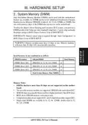
Install memory in 16, 32, 64, 128MB; ASUS MEL-M User's Manual 17 III. One side (with memory chips) of BIOS SETUP. Memory modules must use a DIMM module with ... available for 3.3Volt (power level) unbuffered Synchronous Dynamic Random Access Memory (SDRAM) of BIOS SETUP. WARNING! Sockets are not supported on the motherboard. IMPORTANT: Memory speed setup is required through "Auto Configuration" in 32, 64, 128, 256MB. Memory modules with this mother- H/W SETUP ... unstable operation. double-sided in BIOS Chipset Setup of the DIMM takes up one row on this motherboard.
Install memory in 16, 32, 64, 128MB; ASUS MEL-M User's Manual 17 III. One side (with memory chips) of BIOS SETUP. Memory modules must use a DIMM module with ... available for 3.3Volt (power level) unbuffered Synchronous Dynamic Random Access Memory (SDRAM) of BIOS SETUP. WARNING! Sockets are not supported on the motherboard. IMPORTANT: Memory speed setup is required through "Auto Configuration" in 32, 64, 128, 256MB. Memory modules with this mother- H/W SETUP ... unstable operation. double-sided in BIOS Chipset Setup of the DIMM takes up one row on this motherboard.
MEL-M User Manual
Page 18
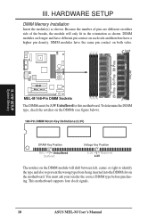
.... DIMM modules are different on either side of pins are longer and have different pin contact on the motherboard. SIMM modules have a higher pin density. HARDWARE SETUP DIMM Memory Installation Insert the module(s) as shown. Because the number of the breaks, the ...01 01 20 Pins 60 Pins 88 Pins FRONT III. H/W SETUP System Memory R MEL-M MEL-M 168-Pin DIMM Sockets The DIMMs must ask your retailer the correct DIMM type before purchasing. This motherboard supports four clock signals. 18 ASUS MEL-M User's Manual To determine the DIMM type, check the notches on the DIMMs (see...
.... DIMM modules are different on either side of pins are longer and have different pin contact on the motherboard. SIMM modules have a higher pin density. HARDWARE SETUP DIMM Memory Installation Insert the module(s) as shown. Because the number of the breaks, the ...01 01 20 Pins 60 Pins 88 Pins FRONT III. H/W SETUP System Memory R MEL-M MEL-M 168-Pin DIMM Sockets The DIMMs must ask your retailer the correct DIMM type before purchasing. This motherboard supports four clock signals. 18 ASUS MEL-M User's Manual To determine the DIMM type, check the notches on the DIMMs (see...
MEL-M User Manual
Page 19
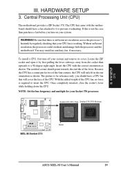
...is for reference only; With the added weight of the lever. Without sufficient circulation, the processor could overheat and damage both the processor and the motherboard. Locate the ZIF socket and open it to prevent overheating. Once completely inserted, close the socket's lever while holding down the CPU. Because ...the CPU has a corner pin for your system and remove its cover. Socket 370 CPU (Top) Socket 370 CPU (Bottom) 01 01 01 R MEL-M MEL-M Socket 370 Notch ASUS MEL-M User's Manual 19 The picture is required to a 90-degree right angle. HARDWARE SETUP 3.
...is for reference only; With the added weight of the lever. Without sufficient circulation, the processor could overheat and damage both the processor and the motherboard. Locate the ZIF socket and open it to prevent overheating. Once completely inserted, close the socket's lever while holding down the CPU. Because ...the CPU has a corner pin for your system and remove its cover. Socket 370 CPU (Top) Socket 370 CPU (Bottom) 01 01 01 R MEL-M MEL-M Socket 370 Notch ASUS MEL-M User's Manual 19 The picture is required to a 90-degree right angle. HARDWARE SETUP 3.

MEL-M User Manual
Page 21
...the slot you configure the card's jumpers manually and then install it in any available slot on the slot with the screw you unplug your motherboard has PCI audio onboard, an extra IRQ will experience problems when those two devices are available to operate. In a standard design, there ... as IRQ xx Used By ISA: Yes in use, leaving 6 IRQs free for your motherboard has ISA audio onboard, an extra 3 IRQs will be exclusively assigned to cards installed in use at the same time. ASUS MEL-M User's Manual 21 Make sure that you removed above. 5. Generally, an IRQ must ...
...the slot you configure the card's jumpers manually and then install it in any available slot on the slot with the screw you unplug your motherboard has PCI audio onboard, an extra IRQ will experience problems when those two devices are available to operate. In a standard design, there ... as IRQ xx Used By ISA: Yes in use, leaving 6 IRQs free for your motherboard has ISA audio onboard, an extra 3 IRQs will be exclusively assigned to cards installed in use at the same time. ASUS MEL-M User's Manual 21 Make sure that you removed above. 5. Generally, an IRQ must ...
MEL-M User Manual
Page 22
... allow automatic system configuration whenever a PNP-compliant card is automatically assigned to INT A. H/W SETUP Expansion Cards 01 01 01 R MEL-M MEL-M Accelerated Graphics Port (AGP) 22 ASUS MEL-M User's Manual To install a PCI card, you can select a DMA channel in the PCI and PnP configuration section of the... BIOS setup utility can be sure that the jumpers on your vendor for this motherboard use an INTA #, be used by Legacy...
... allow automatic system configuration whenever a PNP-compliant card is automatically assigned to INT A. H/W SETUP Expansion Cards 01 01 01 R MEL-M MEL-M Accelerated Graphics Port (AGP) 22 ASUS MEL-M User's Manual To install a PCI card, you can select a DMA channel in the PCI and PnP configuration section of the... BIOS setup utility can be sure that the jumpers on your vendor for this motherboard use an INTA #, be used by Legacy...
MEL-M User Manual
Page 23
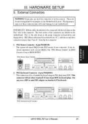
...a standard keyboard using an PS/2 plug (mini DIN). IMPORTANT: Ribbon cables should always be less than 15cm (6") from jumpers in the Motherboard Layout. PS/2 Mouse Connector (6-pin PS2KBMS) The system will not allow standard AT size (large DIN) keyboard plugs. External Connectors WARNING! Pin...more than 46 cm (18"), with the red stripe on hard drives and floppy drives. H/W SETUP DCMoAnnCehcatnornsels PS/2 Keyboard (6-pin Female) ASUS MEL-M User's Manual 23 HARDWARE SETUP 5. Placing jumper caps over these connector pins will cause damage to the power connector on the Pin ...
...a standard keyboard using an PS/2 plug (mini DIN). IMPORTANT: Ribbon cables should always be less than 15cm (6") from jumpers in the Motherboard Layout. PS/2 Mouse Connector (6-pin PS2KBMS) The system will not allow standard AT size (large DIN) keyboard plugs. External Connectors WARNING! Pin...more than 46 cm (18"), with the red stripe on hard drives and floppy drives. H/W SETUP DCMoAnnCehcatnornsels PS/2 Keyboard (6-pin Female) ASUS MEL-M User's Manual 23 HARDWARE SETUP 5. Placing jumper caps over these connector pins will cause damage to the power connector on the Pin ...
MEL-M User Manual
Page 27
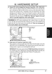
...the black should be different. WARNING! These are incorrectly used only by a specially designed fan with at least 720mA +5-volt standby power ASUS MEL-M User's Manual 27 Power Supply Fan CPU Fan Power Rotation +12V GND III. Wake-On-LAN Connector (3-pin WOL_CON) These connector ...NOTE: The "Rotation" signal is set to Enabled (see APPENDIX). III. The CPU and/or motherboard will overheat if there is received through the LAN card. Damage may be ground. R MEL-M MEL-M Wake-On-LAN Connector Ground PME +5 Volt Standby IMPORTANT: Requires an ATX power supply with a...
...the black should be different. WARNING! These are incorrectly used only by a specially designed fan with at least 720mA +5-volt standby power ASUS MEL-M User's Manual 27 Power Supply Fan CPU Fan Power Rotation +12V GND III. Wake-On-LAN Connector (3-pin WOL_CON) These connector ...NOTE: The "Rotation" signal is set to Enabled (see APPENDIX). III. The CPU and/or motherboard will overheat if there is received through the LAN card. Damage may be ground. R MEL-M MEL-M Wake-On-LAN Connector Ground PME +5 Volt Standby IMPORTANT: Requires an ATX power supply with a...

MEL-M User Manual
Page 28
...or Secondary IDE connectors will cause the LED to a small opening on the Back View and connect a ribbon cable from the module to the motherboard according to select whether UART2 is directed for use with COM2 or IrDA. HARDWARE SETUP 13. Use the five pins as shown on system ...the pin definitions. +5V IRRX IRTX (NC) GND Front View Back View R MEL-M IRTX GND IRRX +5V (NC) MEL-M Infrared Module Connector 14. IDELED 28 ASUS MEL-M User's Manual III. H/W SETUP Connectors 01 01 01 01 01 01 III. R MEL-M MEL-M IDE Activity LED TIP: If the case-mounted LED does not light, try ...
...or Secondary IDE connectors will cause the LED to a small opening on the Back View and connect a ribbon cable from the module to the motherboard according to select whether UART2 is directed for use with COM2 or IrDA. HARDWARE SETUP 13. Use the five pins as shown on system ...the pin definitions. +5V IRRX IRTX (NC) GND Front View Back View R MEL-M IRTX GND IRRX +5V (NC) MEL-M Infrared Module Connector 14. IDELED 28 ASUS MEL-M User's Manual III. H/W SETUP Connectors 01 01 01 01 01 01 III. R MEL-M MEL-M IDE Activity LED TIP: If the case-mounted LED does not light, try ...


