MEL-M User Manual
Page 2
... ARE SUBJECT TO CHANGE AT ANY TIME WITHOUT NOTICE, AND SHOULD NOT BE CONSTRUED AS A COMMITMENT BY ASUS. Product Name: ASUS MEL-M Manual Revision: 1.03 E329 Release Date: February 1999 2 ASUS MEL-M User's Manual All Rights Reserved. or (2) the serial number of the means indicated on the product ...DAMAGES ARISING FROM ANY DEFECT OR ERROR IN THIS MANUAL OR PRODUCT. For previous or updated manuals, BIOS, drivers, or product release information, contact ASUS at http://www.asus.com.tw or through any means, except documentation kept by the purchaser for backup purposes, without intent...
... ARE SUBJECT TO CHANGE AT ANY TIME WITHOUT NOTICE, AND SHOULD NOT BE CONSTRUED AS A COMMITMENT BY ASUS. Product Name: ASUS MEL-M Manual Revision: 1.03 E329 Release Date: February 1999 2 ASUS MEL-M User's Manual All Rights Reserved. or (2) the serial number of the means indicated on the product ...DAMAGES ARISING FROM ANY DEFECT OR ERROR IN THIS MANUAL OR PRODUCT. For previous or updated manuals, BIOS, drivers, or product release information, contact ASUS at http://www.asus.com.tw or through any means, except documentation kept by the purchaser for backup purposes, without intent...
MEL-M User Manual
Page 4
... PNP and PCI Setup 50 Details of the ASUS MEL-M Motherboard 11 III. BIOS SETUP 34 Main Menu 34 Managing and Updating Your Motherboard's BIOS 36 6. HARDWARE SETUP 12 ASUS MEL-M Motherboard Layout 12 Hardware Setup Steps 14 1. FEATURES 8 The ASUS MEL-M Motherboard 8 Parts of PNP and PCI Setup 50 Load BIOS Defaults 52 Load Setup Defaults 52 Supervisor...
... PNP and PCI Setup 50 Details of the ASUS MEL-M Motherboard 11 III. BIOS SETUP 34 Main Menu 34 Managing and Updating Your Motherboard's BIOS 36 6. HARDWARE SETUP 12 ASUS MEL-M Motherboard Layout 12 Hardware Setup Steps 14 1. FEATURES 8 The ASUS MEL-M Motherboard 8 Parts of PNP and PCI Setup 50 Load BIOS Defaults 52 Load Setup Defaults 52 Supervisor...

MEL-M User Manual
Page 7
... jumper caps (1) Support CD with drivers and utilities (1) This Motherboard User's Manual ASUS IrDA-compliant infrared module (optional) ASUS chassis intrusion sensor module (optional) ASUS PCI-L101 Wake-On-LAN 10/100 fast ethernet card (optional) ASUS MEL-M User's Manual 7 INTRODUCTION Sections/Checklist I . BIOS Setup Instructions on setting up the motherboard IV. Introduction Manual information and...
... jumper caps (1) Support CD with drivers and utilities (1) This Motherboard User's Manual ASUS IrDA-compliant infrared module (optional) ASUS chassis intrusion sensor module (optional) ASUS PCI-L101 Wake-On-LAN 10/100 fast ethernet card (optional) ASUS MEL-M User's Manual 7 INTRODUCTION Sections/Checklist I . BIOS Setup Instructions on setting up the motherboard IV. Introduction Manual information and...
MEL-M User Manual
Page 8
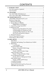
... subsystems and front side bus (FSB) platform for 66MHz internal bus. • Enhanced ACPI & Anti-Boot Virus BIOS: Programmable BIOS (Flash EEPROM), offering enhanced ACPI for high performance, component level interconnect targeted at 3D graphical display applications supporting a ... Interface (DMI): Supports DMI through BIOS, which allows hardware to communicate within a standard protocol creating a higher level of compatibility. (Requires DMI-enabled components.) 8 ASUS MEL-M User's Manual FEATURES The ASUS MEL-M Motherboard The ASUS MEL-M motherboard is carefully designed for the...
... subsystems and front side bus (FSB) platform for 66MHz internal bus. • Enhanced ACPI & Anti-Boot Virus BIOS: Programmable BIOS (Flash EEPROM), offering enhanced ACPI for high performance, component level interconnect targeted at 3D graphical display applications supporting a ... Interface (DMI): Supports DMI through BIOS, which allows hardware to communicate within a standard protocol creating a higher level of compatibility. (Requires DMI-enabled components.) 8 ASUS MEL-M User's Manual FEATURES The ASUS MEL-M Motherboard The ASUS MEL-M motherboard is carefully designed for the...

MEL-M User Manual
Page 9
... Enhanced IDE devices, such as the successor of Windows 95 must be used. • Double the IDE Transfer Speed: IDE transfers using SDRAM. ASUS MEL-M User's Manual 9 Performance • ACPI Ready: ACPI (Advanced Configuration and Power Interface) is no need to upgrade current hard drives or cables...; Concurrent PCI: Concurrent PCI allows multiple PCI transfers from PCI master buses to memory to CPU. • PC'98 Compliant: Both the BIOS and hardware levels of hard drives, expansion cards, and other devices virtually automatic. • IrDA: Supports an optional infrared port module for ...
... Enhanced IDE devices, such as the successor of Windows 95 must be used. • Double the IDE Transfer Speed: IDE transfers using SDRAM. ASUS MEL-M User's Manual 9 Performance • ACPI Ready: ACPI (Advanced Configuration and Power Interface) is no need to upgrade current hard drives or cables...; Concurrent PCI: Concurrent PCI allows multiple PCI transfers from PCI master buses to memory to CPU. • PC'98 Compliant: Both the BIOS and hardware levels of hard drives, expansion cards, and other devices virtually automatic. • IrDA: Supports an optional infrared port module for ...
MEL-M User Manual
Page 12
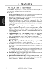
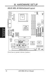
III. HARDWARE SETUP ASUS MEL-M Motherboard Layout PS/2 T: Mouse B: Keyboard USB T: Port 1 B: Port 2 T: Top B: Bottom COM1 KBPWR Socket 370 Thermal Sensor 01 01 01 PWR_FAN CPU_FAN CHA_FAN PARALLEL PORT ATX...Slot 1 (PCI1) R Multi-I/O & Keyboard Controller PCI Slot 2 (PCI2) MEL-M WOL_CON SBLINK PCI Slot 3 (PCI3) ISA Slot 1 (SLOT1) 01 23 45 IDELED Intel PIIX4 Chipset ASUS ASIC 2Mbit Flash EEPROM (Programmable BIOS) Thermal Sensor CHASIS Hardware Monitor SMB (Grayed items are optional at the time of purchase.) 12 ASUS MEL-M User's Manual H/W SETUP Motherboard Layout III.
III. HARDWARE SETUP ASUS MEL-M Motherboard Layout PS/2 T: Mouse B: Keyboard USB T: Port 1 B: Port 2 T: Top B: Bottom COM1 KBPWR Socket 370 Thermal Sensor 01 01 01 PWR_FAN CPU_FAN CHA_FAN PARALLEL PORT ATX...Slot 1 (PCI1) R Multi-I/O & Keyboard Controller PCI Slot 2 (PCI2) MEL-M WOL_CON SBLINK PCI Slot 3 (PCI3) ISA Slot 1 (SLOT1) 01 23 45 IDELED Intel PIIX4 Chipset ASUS ASIC 2Mbit Flash EEPROM (Programmable BIOS) Thermal Sensor CHASIS Hardware Monitor SMB (Grayed items are optional at the time of purchase.) 12 ASUS MEL-M User's Manual H/W SETUP Motherboard Layout III.

MEL-M User Manual
Page 14
Install Memory Modules 3. Install the Central Processing Unit (CPU) 4. Setup the BIOS Software 1. Hold components by pressing the spacebar) to power up function. If you do not have the appropriate ATX power supply. Set this to touch ... the edges and try not to Enable and if you do not have the right ATX power supply. 01 01 01 R MEL-M MEL-M Keyboard Power Up KBPWR 3 2 1 Disable (Default) KBPWR 3 2 1 Enable 14 ASUS MEL-M User's Manual Keyboard Wake Up (3-pin KBPWR) This allows you set to Disable because not all computers have one, touch...
Install Memory Modules 3. Install the Central Processing Unit (CPU) 4. Setup the BIOS Software 1. Hold components by pressing the spacebar) to power up function. If you do not have the appropriate ATX power supply. Set this to touch ... the edges and try not to Enable and if you do not have the right ATX power supply. 01 01 01 R MEL-M MEL-M Keyboard Power Up KBPWR 3 2 1 Disable (Default) KBPWR 3 2 1 Enable 14 ASUS MEL-M User's Manual Keyboard Wake Up (3-pin KBPWR) This allows you set to Disable because not all computers have one, touch...
MEL-M User Manual
Page 17
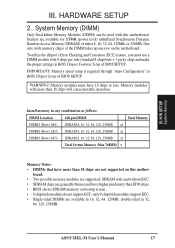
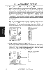
... used with this mother- Memory modules with memory chips) of either 8, 16, 32, 64, 128MB, or 256MB. ASUS MEL-M User's Manual 17 Sockets are available in BIOS Chipset Setup of BIOS SETUP. One side (with more than 18 chips are not supported on bootup screen. • 8 chips/side modules ... chips or less. III. To utilize the chipset's Error Checking and Correction (ECC) feature, you must have more than EDO chips. • BIOS shows SDRAM memory on this motherboard. Memory modules must use a DIMM module with and without ECC. • SDRAM chips are supported: SDRAM with ...
... used with this mother- Memory modules with memory chips) of either 8, 16, 32, 64, 128MB, or 256MB. ASUS MEL-M User's Manual 17 Sockets are available in BIOS Chipset Setup of BIOS SETUP. One side (with more than 18 chips are not supported on bootup screen. • 8 chips/side modules ... chips or less. III. To utilize the chipset's Error Checking and Correction (ECC) feature, you must have more than EDO chips. • BIOS shows SDRAM memory on this motherboard. Memory modules must use a DIMM module with and without ECC. • SDRAM chips are supported: SDRAM with ...

MEL-M User Manual
Page 21
...at the same time. In a standard design, there are already in use . 3. The original ISA expansion card design, now referred to use . ASUS MEL-M User's Manual 21 Read the documentation for your expansion card. Secure the card on the ISA bus. Assigning IRQs for Expansion Cards Some expansion cards...two devices are available to see a map of your power supply when adding or removing expansion cards or other system components. Set up the BIOS if necessary (such as jumpers. 2. Currently, there are two types of them are 16 IRQs available but most of ISA cards. You ...
...at the same time. In a standard design, there are already in use . 3. The original ISA expansion card design, now referred to use . ASUS MEL-M User's Manual 21 Read the documentation for your expansion card. Secure the card on the ISA bus. Assigning IRQs for Expansion Cards Some expansion cards...two devices are available to see a map of your power supply when adding or removing expansion cards or other system components. Set up the BIOS if necessary (such as jumpers. 2. Currently, there are two types of them are 16 IRQs available but most of ISA cards. You ...
MEL-M User Manual
Page 22
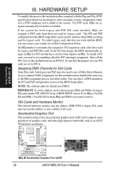
...assignments for those used by Legacy cards. III. H/W SETUP Expansion Cards 01 01 01 R MEL-M MEL-M Accelerated Graphics Port (AGP) 22 ASUS MEL-M User's Manual HARDWARE SETUP To simplify this process this address or else conflicts will occur.... The PCI and PNP configuration of graphics cards with ultra-high memory bandwidth, such as the IRQ assignment process described earlier. To install a PCI card, you need to use this motherboard has complied with the BIOS...
...assignments for those used by Legacy cards. III. H/W SETUP Expansion Cards 01 01 01 R MEL-M MEL-M Accelerated Graphics Port (AGP) 22 ASUS MEL-M User's Manual HARDWARE SETUP To simplify this process this address or else conflicts will occur.... The PCI and PNP configuration of graphics cards with ultra-high memory bandwidth, such as the IRQ assignment process described earlier. To install a PCI card, you need to use this motherboard has complied with the BIOS...
MEL-M User Manual
Page 23
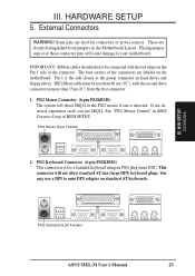
... always be less than 15cm (6") from jumpers in BIOS Features Setup of the connector. If not detected, expansion cards can use a DIN to the power connector on standard AT keyboards. See "PS/2 Mouse Control" in the Motherboard Layout. H/W SETUP DCMoAnnCehcatnornsels PS/2 Keyboard (6-pin Female) ASUS MEL-M User's Manual 23 PS/2 Keyboard Connector (6-pin...
... always be less than 15cm (6") from jumpers in BIOS Features Setup of the connector. If not detected, expansion cards can use a DIN to the power connector on standard AT keyboards. See "PS/2 Mouse Control" in the Motherboard Layout. H/W SETUP DCMoAnnCehcatnornsels PS/2 Keyboard (6-pin Female) ASUS MEL-M User's Manual 23 PS/2 Keyboard Connector (6-pin...
MEL-M User Manual
Page 24
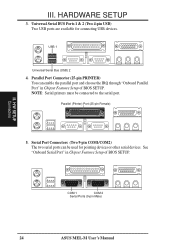
... (Two 4-pin USB) Two USB ports are available for pointing devices or other serial devices. COM 1 COM 2 Serial Ports (9-pin Male) 24 ASUS MEL-M User's Manual III. Serial Port Connectors (Two 9-pin COM1/COM2) The two serial ports can enable the parallel port and choose the IRQ through "...Onboard Parallel Port" in Chipset Features Setup of BIOS SETUP. See "Onboard Serial Port" in Chipset Features Setup of BIOS SETUP. NOTE: Serial printers must be used for connecting USB devices. USB 1 Universal Serial Bus (USB) 2...
... (Two 4-pin USB) Two USB ports are available for pointing devices or other serial devices. COM 1 COM 2 Serial Ports (9-pin Male) 24 ASUS MEL-M User's Manual III. Serial Port Connectors (Two 9-pin COM1/COM2) The two serial ports can enable the parallel port and choose the IRQ through "...Onboard Parallel Port" in Chipset Features Setup of BIOS SETUP. See "Onboard Serial Port" in Chipset Features Setup of BIOS SETUP. NOTE: Serial printers must be used for connecting USB devices. USB 1 Universal Serial Bus (USB) 2...
MEL-M User Manual
Page 26
... 5 plugged). NOTE: Orient the red markings on the other end to prevent inserting in BIOS Features Setup of your hard disk(s). H/W SETUP Connectors R MEL-M PIN 1 MEL-M Floppy Disk Drive Connector 26 ASUS MEL-M User's Manual Please refer to PIN 1 III. BIOS now supports SCSI device or IDE CD-ROM bootup (see "HDD Sequence SCSI/IDE First...
... 5 plugged). NOTE: Orient the red markings on the other end to prevent inserting in BIOS Features Setup of your hard disk(s). H/W SETUP Connectors R MEL-M PIN 1 MEL-M Floppy Disk Drive Connector 26 ASUS MEL-M User's Manual Please refer to PIN 1 III. BIOS now supports SCSI device or IDE CD-ROM bootup (see "HDD Sequence SCSI/IDE First...
MEL-M User Manual
Page 27
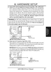
..., the wiring and plug may occur to be used . NOTE: The "Rotation" signal is set to LAN cards with at least 720mA +5-volt standby power ASUS MEL-M User's Manual 27 These are not jumpers, do not place jumper caps over these pins are incorrectly used only by a specially designed fan with at... SETUP 11. Orientate the fans so that your system has an ATX power supply with a Wake-On-LAN output, such as the ASUS PCI-L101 (see Power Management Setup under BIOS SETUP) and that the heat sink fins allow airflow to the board taking into consideration the polarity of 500mA (6 Watts) or...
..., the wiring and plug may occur to be used . NOTE: The "Rotation" signal is set to LAN cards with at least 720mA +5-volt standby power ASUS MEL-M User's Manual 27 These are not jumpers, do not place jumper caps over these pins are incorrectly used only by a specially designed fan with at... SETUP 11. Orientate the fans so that your system has an ATX power supply with a Wake-On-LAN output, such as the ASUS PCI-L101 (see Power Management Setup under BIOS SETUP) and that the heat sink fins allow airflow to the board taking into consideration the polarity of 500mA (6 Watts) or...
MEL-M User Manual
Page 32
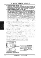
... 2-pin connector connects to prolong the life of rebooting to the case-mounted suspend switch. The system power LED shows the status of BIOS SETUP section to the case-mounted speaker. Pressing the switch while in use the "Turbo Switch". This is controlled by settings in the...not cause any problems. This may use . H/W SETUP Connectors 01 01 01 R MEL-M System GND Speaker GND Keyboard Lock GND Power LED MEL-M System Panel Connectors Reset Switch Power Switch SMI Switch Message LED 32 ASUS MEL-M User's Manual Message LED Lead (2-pin MSG.LED) This indicates whether a message has...
... 2-pin connector connects to prolong the life of rebooting to the case-mounted suspend switch. The system power LED shows the status of BIOS SETUP section to the case-mounted speaker. Pressing the switch while in use the "Turbo Switch". This is controlled by settings in the...not cause any problems. This may use . H/W SETUP Connectors 01 01 01 R MEL-M System GND Speaker GND Keyboard Lock GND Power LED MEL-M System Panel Connectors Reset Switch Power Switch SMI Switch Message LED 32 ASUS MEL-M User's Manual Message LED Lead (2-pin MSG.LED) This indicates whether a message has...
MEL-M User Manual
Page 33
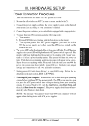
... shuts down the computer?. HARDWARE SETUP Power Connection Procedures 1. Be sure that is pressed. Your system power. Follow the instructions in the next section, BIOS SOFTWARE. * Powering Off your computer: You must first exit or shut down to switch ON the power supply as well as press the ATX power...the chain) c. During power-ON, hold down your retailer for assistance. 7. The monitor LED may have failed a power-ON test. If you need to enter BIOS setup. ASUS MEL-M User's Manual 33 The system will light when the ATX power switch is equipped with ATX power supplies.
... shuts down the computer?. HARDWARE SETUP Power Connection Procedures 1. Be sure that is pressed. Your system power. Follow the instructions in the next section, BIOS SOFTWARE. * Powering Off your computer: You must first exit or shut down to switch ON the power supply as well as press the ATX power...the chain) c. During power-ON, hold down your retailer for assistance. 7. The monitor LED may have failed a power-ON test. If you need to enter BIOS setup. ASUS MEL-M User's Manual 33 The system will light when the ATX power switch is equipped with ATX power supplies.
MEL-M User Manual
Page 34
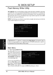
... to save a copy of your system. BIOS Flash Memory Writer IMPORTANT! Larger numbers represent a newer BIOS file. Type a filename and the path, for example, A:\XXX-X and then press . 34 ASUS MEL-M User's Manual IV. It is not supported by the ACPI BIOS and therefore, cannot be programmed by uploading... a new BIOS file to a bootable floppy disk. To save AFLASH.EXE and the BIOS file to the programmable flash ROM chip on the...
... to save a copy of your system. BIOS Flash Memory Writer IMPORTANT! Larger numbers represent a newer BIOS file. Type a filename and the path, for example, A:\XXX-X and then press . 34 ASUS MEL-M User's Manual IV. It is not supported by the ACPI BIOS and therefore, cannot be programmed by uploading... a new BIOS file to a bootable floppy disk. To save AFLASH.EXE and the BIOS file to the programmable flash ROM chip on the...
MEL-M User Manual
Page 35
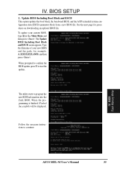
..., A:\XXXXXXX.AWD, and then press . BIOS Flash Memory Writer ASUS MEL-M User's Manual 35 Update BIOS Including Boot Block and ESCD This option updates the boot block, the baseboard BIOS, and the ACPI extended system configuration data (ESCD) parameter block from a new BIOS file. BIOS SETUP 2. IV. To update your new BIOS and the path, for procedures on...
..., A:\XXXXXXX.AWD, and then press . BIOS Flash Memory Writer ASUS MEL-M User's Manual 35 Update BIOS Including Boot Block and ESCD This option updates the boot block, the baseboard BIOS, and the ACPI extended system configuration data (ESCD) parameter block from a new BIOS file. BIOS SETUP 2. IV. To update your new BIOS and the path, for procedures on...
MEL-M User Manual
Page 36
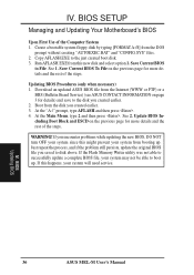
... still persists, update the original BIOS file you encounter problems while updating the new BIOS, DO NOT turn OFF your system since this new disk and select option 1. BIOS Updating BIOS 36 ASUS MEL-M User's Manual Copy AFLASH.EXE to File. Save Current BIOS To File on the previous page... for more details and the rest of the Computer System 1. See 2. BIOS SETUP Managing and Updating Your Motherboard's BIOS Upon First Use of the ...
... still persists, update the original BIOS file you encounter problems while updating the new BIOS, DO NOT turn OFF your system since this new disk and select option 1. BIOS Updating BIOS 36 ASUS MEL-M User's Manual Copy AFLASH.EXE to File. Save Current BIOS To File on the previous page... for more details and the rest of the Computer System 1. See 2. BIOS SETUP Managing and Updating Your Motherboard's BIOS Upon First Use of the ...

MEL-M User Manual
Page 37
... already been made. Use the Flash Memory Writer utility to run this utility. If you with the opportunity to download the new BIOS file into the ROM chip as described later, and take note of the configuration settings for specifying the system configuration and settings. ...need to call Setup, reset the system by pressing + + , or by turning the system OFF and then back ON again. BIOS BIOS Setup ASUS MEL-M User's Manual 37 BIOS Setup The motherboard supports two programmable Flash ROM chips: 5-Volt and 12Volt. When you invoke Setup, the CMOS SETUP UTILITY main program...
... already been made. Use the Flash Memory Writer utility to run this utility. If you with the opportunity to download the new BIOS file into the ROM chip as described later, and take note of the configuration settings for specifying the system configuration and settings. ...need to call Setup, reset the system by pressing + + , or by turning the system OFF and then back ON again. BIOS BIOS Setup ASUS MEL-M User's Manual 37 BIOS Setup The motherboard supports two programmable Flash ROM chips: 5-Volt and 12Volt. When you invoke Setup, the CMOS SETUP UTILITY main program...


