MEL-M User Manual
Page 1
R MEL-M Socket 370 microATX Motherboard USER'S MANUAL
R MEL-M Socket 370 microATX Motherboard USER'S MANUAL
MEL-M User Manual
Page 4
...DIMM 17 DIMM Memory Installation 18 3. External Connectors 23 Power Connection Procedures 33 Flash Memory Writer Utility 34 IV. FEATURES 8 The ASUS MEL-M Motherboard 8 Parts of PNP and PCI Setup 50 Load BIOS Defaults 52 Load Setup Defaults 52 Supervisor Password and User Password 53 IDE ... Setup 44 Power Management Setup 47 Details of Power Management Setup 47 PNP and PCI Setup 50 Details of the ASUS MEL-M Motherboard 11 III. Motherboard Settings 14 2. Expansion Cards 21 Expansion Card Installation Procedure 21 Assigning IRQs for Expansion Cards 21 Assigning DMA Channels ...
...DIMM 17 DIMM Memory Installation 18 3. External Connectors 23 Power Connection Procedures 33 Flash Memory Writer Utility 34 IV. FEATURES 8 The ASUS MEL-M Motherboard 8 Parts of PNP and PCI Setup 50 Load BIOS Defaults 52 Load Setup Defaults 52 Supervisor Password and User Password 53 IDE ... Setup 44 Power Management Setup 47 Details of Power Management Setup 47 PNP and PCI Setup 50 Details of the ASUS MEL-M Motherboard 11 III. Motherboard Settings 14 2. Expansion Cards 21 Expansion Card Installation Procedure 21 Assigning IRQs for Expansion Cards 21 Assigning DMA Channels ...

MEL-M User Manual
Page 7
...on setting up the BIOS software V. Software Reference Reference material for the included support software Item Checklist Check that your retailer. (1) ASUS Motherboard (1) IDE ribbon cable for master and slave drives (1) Ribbon cable for (1) 5.25" and (2) 3.5" floppy disk drives (1) Bag... of spare jumper caps (1) Support CD with drivers and utilities (1) This Motherboard User's Manual ASUS IrDA-compliant infrared module (optional) ASUS chassis intrusion sensor module (optional) ASUS PCI-L101 Wake-On-LAN 10/100 fast ethernet card (optional) ASUS MEL-M User's Manual 7
...on setting up the BIOS software V. Software Reference Reference material for the included support software Item Checklist Check that your retailer. (1) ASUS Motherboard (1) IDE ribbon cable for master and slave drives (1) Ribbon cable for (1) 5.25" and (2) 3.5" floppy disk drives (1) Bag... of spare jumper caps (1) Support CD with drivers and utilities (1) This Motherboard User's Manual ASUS IrDA-compliant infrared module (optional) ASUS chassis intrusion sensor module (optional) ASUS PCI-L101 Wake-On-LAN 10/100 fast ethernet card (optional) ASUS MEL-M User's Manual 7
MEL-M User Manual
Page 8
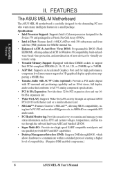
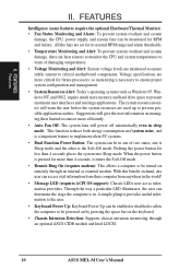
... PCI expansion slots and one 16bit ISA expansion slot . • Wake-On-LAN: Supports Wake-On-LAN activity through an optional ASUS PCI-L101 Fast Ethernet card or a similar ethernet card. • SB-Link™: Features Creative's SB-Link™, allowing SB16...• AGP Slot: Supports an Accelerated Graphics Port card for Windows 98 compatibility, built-in a small package. FEATURES The ASUS MEL-M Motherboard The ASUS MEL-M motherboard is carefully designed for the demanding PC user who wants many intelligent features in hardware-based virus protection, and autodetection of compatibility....
... PCI expansion slots and one 16bit ISA expansion slot . • Wake-On-LAN: Supports Wake-On-LAN activity through an optional ASUS PCI-L101 Fast Ethernet card or a similar ethernet card. • SB-Link™: Features Creative's SB-Link™, allowing SB16...• AGP Slot: Supports an Accelerated Graphics Port card for Windows 98 compatibility, built-in a small package. FEATURES The ASUS MEL-M Motherboard The ASUS MEL-M motherboard is carefully designed for the demanding PC user who wants many intelligent features in hardware-based virus protection, and autodetection of compatibility....

MEL-M User Manual
Page 9
... more Energy Saving Features for Windows 95/98/NT.• SDRAM Optimized Performance: ASUS smart series motherboards support the new generation memory, Synchronous Dynamic Random Access Memory (SDRAM), which increases... Adjustments: Easy-to CPU. • PC'98 Compliant: Both the BIOS and hardware levels of motherboards. The best of all ASUS smart series of the motherboard meets PC'98 compliancy. II. With these features implemented in two channels, supports Ultra DMA/33,...make changing CPU and onboard features settings a snap. FEATURES Features II. ASUS MEL-M User's Manual 9
... more Energy Saving Features for Windows 95/98/NT.• SDRAM Optimized Performance: ASUS smart series motherboards support the new generation memory, Synchronous Dynamic Random Access Memory (SDRAM), which increases... Adjustments: Easy-to CPU. • PC'98 Compliant: Both the BIOS and hardware levels of motherboards. The best of all ASUS smart series of the motherboard meets PC'98 compliancy. II. With these features implemented in two channels, supports Ultra DMA/33,...make changing CPU and onboard features settings a snap. FEATURES Features II. ASUS MEL-M User's Manual 9
MEL-M User Manual
Page 10
... two states, one of damaging temperatures. • Voltage Monitoring and Alert: System voltage levels are monitored to ensure stable current to critical motherboard components. II. All the fans are used up to present enormous user interfaces and run large applications. Pushing the power button for RPM...is in one is Sleep mode and the other is the Soft-Off mode. With this benefit on remotely through an optional ASUS CIDB module and Intel LDCM. 10 ASUS MEL-M User's Manual A simple glimpse provides useful information to be turned on -hand, any user can be monitored for less...
... two states, one of damaging temperatures. • Voltage Monitoring and Alert: System voltage levels are monitored to ensure stable current to critical motherboard components. II. All the fans are used up to present enormous user interfaces and run large applications. Pushing the power button for RPM...is in one is Sleep mode and the other is the Soft-Off mode. With this benefit on remotely through an optional ASUS CIDB module and Intel LDCM. 10 ASUS MEL-M User's Manual A simple glimpse provides useful information to be turned on -hand, any user can be monitored for less...
MEL-M User Manual
Page 11
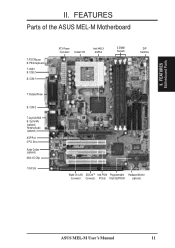
II. FEATURES Parts of the ASUS MEL-M Motherboard T: PS/2 Mouse B: PS/2 Keyboard T: USB 1 B: USB 2 B: COM 1 T: Parallel/Printer B: COM 2 T: Joystick/Midi B: Out/In/Mic (optional) Yamaha Audio (optional) AGP Port 3 PCI Slots Audio Codec (optional) Multi-I/O Chip 1 ISA Slot ATX Power Connector Socket 370 Intel 440LX AGPset 3 DIMM Sockets DIP Switches Wake-On-LAN SB-LinkTM Intel PIIX4 Programmable Hardware Monitor Connector Connector PCIset Flash EEPROM (optional) ASUS MEL-M User's Manual 11 FEATURES Motherboard Parts II.
II. FEATURES Parts of the ASUS MEL-M Motherboard T: PS/2 Mouse B: PS/2 Keyboard T: USB 1 B: USB 2 B: COM 1 T: Parallel/Printer B: COM 2 T: Joystick/Midi B: Out/In/Mic (optional) Yamaha Audio (optional) AGP Port 3 PCI Slots Audio Codec (optional) Multi-I/O Chip 1 ISA Slot ATX Power Connector Socket 370 Intel 440LX AGPset 3 DIMM Sockets DIP Switches Wake-On-LAN SB-LinkTM Intel PIIX4 Programmable Hardware Monitor Connector Connector PCIset Flash EEPROM (optional) ASUS MEL-M User's Manual 11 FEATURES Motherboard Parts II.
MEL-M User Manual
Page 12
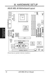
HARDWARE SETUP ASUS MEL-M Motherboard Layout PS/2 T: Mouse B: Keyboard USB T: Port 1 B: Port 2 T: Top B: Bottom COM1 KBPWR Socket 370 Thermal Sensor 01 01 01 PWR_FAN CPU_FAN CHA_FAN PARALLEL PORT ATX ...1 (PCI1) R Multi-I/O & Keyboard Controller PCI Slot 2 (PCI2) MEL-M WOL_CON SBLINK PCI Slot 3 (PCI3) ISA Slot 1 (SLOT1) 01 23 45 IDELED Intel PIIX4 Chipset ASUS ASIC 2Mbit Flash EEPROM (Programmable BIOS) Thermal Sensor CHASIS Hardware Monitor SMB (Grayed items are optional at the time of purchase.) 12 ASUS MEL-M User's Manual III. H/W SETUP Motherboard Layout III.
HARDWARE SETUP ASUS MEL-M Motherboard Layout PS/2 T: Mouse B: Keyboard USB T: Port 1 B: Port 2 T: Top B: Bottom COM1 KBPWR Socket 370 Thermal Sensor 01 01 01 PWR_FAN CPU_FAN CHA_FAN PARALLEL PORT ATX ...1 (PCI1) R Multi-I/O & Keyboard Controller PCI Slot 2 (PCI2) MEL-M WOL_CON SBLINK PCI Slot 3 (PCI3) ISA Slot 1 (SLOT1) 01 23 45 IDELED Intel PIIX4 Chipset ASUS ASIC 2Mbit Flash EEPROM (Programmable BIOS) Thermal Sensor CHASIS Hardware Monitor SMB (Grayed items are optional at the time of purchase.) 12 ASUS MEL-M User's Manual III. H/W SETUP Motherboard Layout III.

MEL-M User Manual
Page 13
ASUS MEL-M User's Manual 13 otherwise, conflicts will occur. III. H/W SETUP Layout Contents III. HARDWARE SETUP Motherboard Settings 1) KBPWR 2) DIP-Switch 5 3) DIP-Switch 6 4) DIP-Switch 1,2,3,4 5) DIP-Switch 7,8,9,10 p. 14 Keyboard Power Up (Enable/Disable) p. 15 Onboard Audio Setting p. 15 VIO Setting p. 16 ...
ASUS MEL-M User's Manual 13 otherwise, conflicts will occur. III. H/W SETUP Layout Contents III. HARDWARE SETUP Motherboard Settings 1) KBPWR 2) DIP-Switch 5 3) DIP-Switch 6 4) DIP-Switch 1,2,3,4 5) DIP-Switch 7,8,9,10 p. 14 Keyboard Power Up (Enable/Disable) p. 15 Onboard Audio Setting p. 15 VIO Setting p. 16 ...

MEL-M User Manual
Page 14
... Up (3-pin KBPWR) This allows you do not have the right ATX power supply. 01 01 01 R MEL-M MEL-M Keyboard Power Up KBPWR 3 2 1 Disable (Default) KBPWR 3 2 1 Enable 14 ASUS MEL-M User's Manual This feature requires an ATX power supply that came with the component whenever the components are separated...Integrated Circuit (IC) chips. To protect them against damage from the system. 1. Unplug your computer, you work on the inside. 2. Check Motherboard Settings 2. Place components on a grounded antistatic pad or on the bag that can supply at least 300mA on if you set to disable or...
... Up (3-pin KBPWR) This allows you do not have the right ATX power supply. 01 01 01 R MEL-M MEL-M Keyboard Power Up KBPWR 3 2 1 Disable (Default) KBPWR 3 2 1 Enable 14 ASUS MEL-M User's Manual This feature requires an ATX power supply that came with the component whenever the components are separated...Integrated Circuit (IC) chips. To protect them against damage from the system. 1. Unplug your computer, you work on the inside. 2. Check Motherboard Settings 2. Place components on a grounded antistatic pad or on the bag that can supply at least 300mA on if you set to disable or...

MEL-M User Manual
Page 15
The white block represents the switch's position. The example below shows all the switches in the OFF position. III. R MEL-M MEL-M DIP Switches 01 01 01 ON 1 2 3 4 5 6 7 8 9 10 OFF ON HARDWARE SETUP Motherboard Settings (DIP Switches) Some of the motherboard's onboard functions can be adjusted through the DIP switches.
The white block represents the switch's position. The example below shows all the switches in the OFF position. III. R MEL-M MEL-M DIP Switches 01 01 01 ON 1 2 3 4 5 6 7 8 9 10 OFF ON HARDWARE SETUP Motherboard Settings (DIP Switches) Some of the motherboard's onboard functions can be adjusted through the DIP switches.
MEL-M User Manual
Page 16
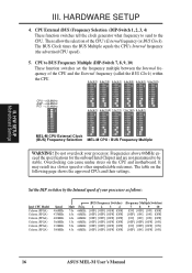
... BUS Clock times the BUS Multiple equals the CPU's Internal frequency (the advertised CPU speed). 5. The table on the CPU and motherboard. HARDWARE SETUP 4. These allow the selection of the CPU and the External frequency (called the BUS Clock) within the CPU. 3.0x... 66MHz [OFF] [OFF] [OFF] [OFF] [OFF] [ON] [OFF] [ON] 16 ASUS MEL-M User's Manual III. Overclocking can cause undue stress on the following page shows the approved CPUs and their settings. H/W SETUP Motherboard Settings III. CPU External (BUS) Frequency Selection (DIP-Switch 1, 2, 3, 4) These function switches ...
... BUS Clock times the BUS Multiple equals the CPU's Internal frequency (the advertised CPU speed). 5. The table on the CPU and motherboard. HARDWARE SETUP 4. These allow the selection of the CPU and the External frequency (called the BUS Clock) within the CPU. 3.0x... 66MHz [OFF] [OFF] [OFF] [OFF] [OFF] [ON] [OFF] [ON] 16 ASUS MEL-M User's Manual III. Overclocking can cause undue stress on the following page shows the approved CPUs and their settings. H/W SETUP Motherboard Settings III. CPU External (BUS) Frequency Selection (DIP-Switch 1, 2, 3, 4) These function switches ...
MEL-M User Manual
Page 17
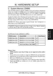
...Setup of either 8, 16, 32, 64, 128MB, or 256MB. ASUS MEL-M User's Manual 17 To utilize the chipset's Error Checking and Correction (ECC) feature, you must have more than EDO chips. • BIOS shows SDRAM memory on the motherboard. Memory modules with 9 chips per side (standard 8 chips/side... (DIMM) Only Dual Inline Memory Modules (DIMM) can be used with and without ECC. • SDRAM chips are not supported on this motherboard. board. • Two possible memory modules are available for 3.3Volt (power level) unbuffered Synchronous Dynamic Random Access Memory (SDRAM) of BIOS ...
...Setup of either 8, 16, 32, 64, 128MB, or 256MB. ASUS MEL-M User's Manual 17 To utilize the chipset's Error Checking and Correction (ECC) feature, you must have more than EDO chips. • BIOS shows SDRAM memory on the motherboard. Memory modules with 9 chips per side (standard 8 chips/side... (DIMM) Only Dual Inline Memory Modules (DIMM) can be used with and without ECC. • SDRAM chips are not supported on this motherboard. board. • Two possible memory modules are available for 3.3Volt (power level) unbuffered Synchronous Dynamic Random Access Memory (SDRAM) of BIOS ...
MEL-M User Manual
Page 18
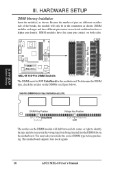
... either side of pins are longer and have a higher pin density. H/W SETUP System Memory R MEL-M MEL-M 168-Pin DIMM Sockets The DIMMs must ask your retailer the correct DIMM type before purchasing. This motherboard supports four clock signals. 18 ASUS MEL-M User's Manual DIMM modules are different on both sides. To determine the DIMM type... Installation Insert the module(s) as shown. Lock 01 01 01 20 Pins 60 Pins 88 Pins FRONT III. You must be 3.3V Unbuffered for this motherboard. III.
... either side of pins are longer and have a higher pin density. H/W SETUP System Memory R MEL-M MEL-M 168-Pin DIMM Sockets The DIMMs must ask your retailer the correct DIMM type before purchasing. This motherboard supports four clock signals. 18 ASUS MEL-M User's Manual DIMM modules are different on both sides. To determine the DIMM type... Installation Insert the module(s) as shown. Lock 01 01 01 20 Pins 60 Pins 88 Pins FRONT III. You must be 3.3V Unbuffered for this motherboard. III.
MEL-M User Manual
Page 19
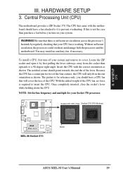
...as shown. The notched corner should have a CPU fan that your system and remove its cover. III. Central Processing Unit (CPU) The motherboard provides a ZIF Socket 370. Once completely inserted, close the socket's lever while holding down the CPU. H/W SETUP CPU III. HARDWARE SETUP ...lever. Without sufficient circulation, the processor could overheat and damage both the processor and the motherboard. Socket 370 CPU (Top) Socket 370 CPU (Bottom) 01 01 01 R MEL-M MEL-M Socket 370 Notch ASUS MEL-M User's Manual 19 The CPU that there is for your system. You may install...
...as shown. The notched corner should have a CPU fan that your system and remove its cover. III. Central Processing Unit (CPU) The motherboard provides a ZIF Socket 370. Once completely inserted, close the socket's lever while holding down the CPU. H/W SETUP CPU III. HARDWARE SETUP ...lever. Without sufficient circulation, the processor could overheat and damage both the processor and the motherboard. Socket 370 CPU (Top) Socket 370 CPU (Bottom) 01 01 01 R MEL-M MEL-M Socket 370 Notch ASUS MEL-M User's Manual 19 The CPU that there is for your system. You may install...

MEL-M User Manual
Page 21
... sure that you intend to operate. If your motherboard has PCI audio onboard, an extra IRQ will be used , leaving 5 IRQs free. Ensure that no two devices share the same IRQs or your used by default uses IRQ 5. ASUS MEL-M User's Manual 21 Read the documentation for your...under Device Manager displays the resource settings being used and free IRQs. H/W SETUP Expansion Cards III. Expansion Card Installation Procedure 1. Remove your motherboard and expansion cards. Keep the bracket for your expansion card, such as IRQ xx Used By ISA: Yes in the ISA expansion bus first...
... sure that you intend to operate. If your motherboard has PCI audio onboard, an extra IRQ will be used , leaving 5 IRQs free. Ensure that no two devices share the same IRQs or your used by default uses IRQ 5. ASUS MEL-M User's Manual 21 Read the documentation for your...under Device Manager displays the resource settings being used and free IRQs. H/W SETUP Expansion Cards III. Expansion Card Installation Procedure 1. Remove your motherboard and expansion cards. Keep the bracket for your expansion card, such as IRQ xx Used By ISA: Yes in the ISA expansion bus first...
MEL-M User Manual
Page 22
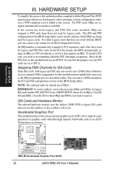
... on this address or else conflicts will occur. Accelerated Graphics Port This motherboard provides an accelerated graphics port (AGP) slot to reserve). III. H/W SETUP Expansion Cards 01 01 01 R MEL-M MEL-M Accelerated Graphics Port (AGP) 22 ASUS MEL-M User's Manual If the system has both legacy and PnP, may ...channel in IRQ xx Used By ISA and DMA x Used By ISA for this motherboard has complied with the Plug and Play (PNP) specification which IRQs are handled the same way as an ASUS 3D hardware accelerator. NOTE: The onboard audio by Legacy cards. Since all the PCI...
... on this address or else conflicts will occur. Accelerated Graphics Port This motherboard provides an accelerated graphics port (AGP) slot to reserve). III. H/W SETUP Expansion Cards 01 01 01 R MEL-M MEL-M Accelerated Graphics Port (AGP) 22 ASUS MEL-M User's Manual If the system has both legacy and PnP, may ...channel in IRQ xx Used By ISA and DMA x Used By ISA for this motherboard has complied with the Plug and Play (PNP) specification which IRQs are handled the same way as an ASUS 3D hardware accelerator. NOTE: The onboard audio by Legacy cards. Since all the PCI...
MEL-M User Manual
Page 23
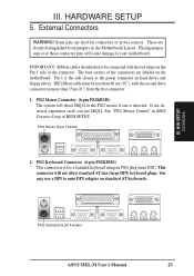
...PS/2 Keyboard Connector (6-pin PS2KBMS) This connection is detected. See "PS/2 Mouse Control" in the Motherboard Layout. HARDWARE SETUP 5. H/W SETUP DCMoAnnCehcatnornsels PS/2 Keyboard (6-pin Female) ASUS MEL-M User's Manual 23 IDE ribbon cable must be connected with the second drive connector no more than ...46 cm (18"), with the red stripe on the motherboard. If not detected, expansion cards can use a ...
...PS/2 Keyboard Connector (6-pin PS2KBMS) This connection is detected. See "PS/2 Mouse Control" in the Motherboard Layout. HARDWARE SETUP 5. H/W SETUP DCMoAnnCehcatnornsels PS/2 Keyboard (6-pin Female) ASUS MEL-M User's Manual 23 IDE ribbon cable must be connected with the second drive connector no more than ...46 cm (18"), with the red stripe on the motherboard. If not detected, expansion cards can use a ...
MEL-M User Manual
Page 27
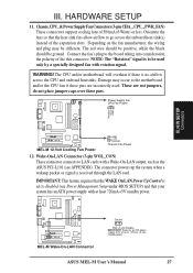
... fans of the this connector. Connect the fan's plug to the motherboard and/or the CPU fan if these pins. R MEL-M MEL-M Wake-On-LAN Connector Ground PME +5 Volt Standby IMPORTANT: Requires an ATX power supply with at least 720mA +5-volt standby power ASUS MEL-M User's Manual 27 Damage may be ground. III. Orientate the...
... fans of the this connector. Connect the fan's plug to the motherboard and/or the CPU fan if these pins. R MEL-M MEL-M Wake-On-LAN Connector Ground PME +5 Volt Standby IMPORTANT: Requires an ATX power supply with at least 720mA +5-volt standby power ASUS MEL-M User's Manual 27 Damage may be ground. III. Orientate the...

MEL-M User Manual
Page 28
...motherboard according to select whether UART2 is directed for use with COM2 or IrDA. Read and write activity by devices connected to the Primary or Secondary IDE connectors will cause the LED to the cabinet's hard disk or IDE activity LED. HARDWARE SETUP 13. IDELED 28 ASUS MEL...-M User's Manual H/W SETUP Connectors 01 01 01 01 01 01 III. IrDA-Compliant Infrared Module Connector (5-pin IR) This connector supports the optional wireless transmitting and receiving infrared module. R MEL-M MEL-M IDE Activity LED TIP: If the ...
...motherboard according to select whether UART2 is directed for use with COM2 or IrDA. Read and write activity by devices connected to the Primary or Secondary IDE connectors will cause the LED to the cabinet's hard disk or IDE activity LED. HARDWARE SETUP 13. IDELED 28 ASUS MEL...-M User's Manual H/W SETUP Connectors 01 01 01 01 01 01 III. IrDA-Compliant Infrared Module Connector (5-pin IR) This connector supports the optional wireless transmitting and receiving infrared module. R MEL-M MEL-M IDE Activity LED TIP: If the ...


