MEL-M User Manual
Page 1
R MEL-M Socket 370 microATX Motherboard USER'S MANUAL
R MEL-M Socket 370 microATX Motherboard USER'S MANUAL
MEL-M User Manual
Page 4
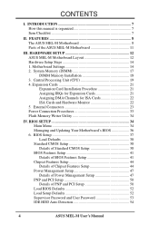
FEATURES 8 The ASUS MEL-M Motherboard 8 Parts of PNP and PCI Setup 50 Load BIOS Defaults 52 Load Setup Defaults 52 Supervisor Password and User Password 53 IDE HDD Auto Detection 54 4 ASUS MEL-M User's Manual CONTENTS I. INTRODUCTION 7 How this manual is organized 7 Item Checklist 7 II. Motherboard Settings 14 2. Expansion Cards 21 ... Setup 44 Power Management Setup 47 Details of Power Management Setup 47 PNP and PCI Setup 50 Details of the ASUS MEL-M Motherboard 11 III. Central Processing Unit (CPU 19 4. BIOS SETUP 34 Main Menu 34 Managing and Updating Your...
FEATURES 8 The ASUS MEL-M Motherboard 8 Parts of PNP and PCI Setup 50 Load BIOS Defaults 52 Load Setup Defaults 52 Supervisor Password and User Password 53 IDE HDD Auto Detection 54 4 ASUS MEL-M User's Manual CONTENTS I. INTRODUCTION 7 How this manual is organized 7 Item Checklist 7 II. Motherboard Settings 14 2. Expansion Cards 21 ... Setup 44 Power Management Setup 47 Details of Power Management Setup 47 PNP and PCI Setup 50 Details of the ASUS MEL-M Motherboard 11 III. Central Processing Unit (CPU 19 4. BIOS SETUP 34 Main Menu 34 Managing and Updating Your...

MEL-M User Manual
Page 7
... II. INTRODUCTION Sections/Checklist I . Software Reference Reference material for the included support software Item Checklist Check that your retailer. (1) ASUS Motherboard (1) IDE ribbon cable for master and slave drives (1) Ribbon cable for (1) 5.25" and (2) 3.5" floppy disk drives (1) Bag...Support CD with drivers and utilities (1) This Motherboard User's Manual ASUS IrDA-compliant infrared module (optional) ASUS chassis intrusion sensor module (optional) ASUS PCI-L101 Wake-On-LAN 10/100 fast ethernet card (optional) ASUS MEL-M User's Manual 7 INTRODUCTION How this product...
... II. INTRODUCTION Sections/Checklist I . Software Reference Reference material for the included support software Item Checklist Check that your retailer. (1) ASUS Motherboard (1) IDE ribbon cable for master and slave drives (1) Ribbon cable for (1) 5.25" and (2) 3.5" floppy disk drives (1) Bag...Support CD with drivers and utilities (1) This Motherboard User's Manual ASUS IrDA-compliant infrared module (optional) ASUS chassis intrusion sensor module (optional) ASUS PCI-L101 Wake-On-LAN 10/100 fast ethernet card (optional) ASUS MEL-M User's Manual 7 INTRODUCTION How this product...
MEL-M User Manual
Page 8
.... Specifications • Intel Processor Support: Supports Intel's Celeron processor designed for the Socket 370 and packaged in a small package. FEATURES The ASUS MEL-M Motherboard The ASUS MEL-M motherboard is carefully designed for high performance, component level interconnect targeted at 3D graphical display applications supporting a 66MHz bus. • Yamaha Audio with AC... (8, 16, 32, 64, 128, or 256MB) up to communicate within a standard protocol creating a higher level of compatibility. (Requires DMI-enabled components.) 8 ASUS MEL-M User's Manual FEATURES Features II.
.... Specifications • Intel Processor Support: Supports Intel's Celeron processor designed for the Socket 370 and packaged in a small package. FEATURES The ASUS MEL-M Motherboard The ASUS MEL-M motherboard is carefully designed for high performance, component level interconnect targeted at 3D graphical display applications supporting a 66MHz bus. • Yamaha Audio with AC... (8, 16, 32, 64, 128, or 256MB) up to communicate within a standard protocol creating a higher level of compatibility. (Requires DMI-enabled components.) 8 ASUS MEL-M User's Manual FEATURES Features II.

MEL-M User Manual
Page 9
...Enhanced IDE devices, such as the successor of Windows 95 must be ready around the clock, yet satisfy all the energy saving standards. ASUS MEL-M User's Manual 9 Performance • ACPI Ready: ACPI (Advanced Configuration and Power Interface) is no need to upgrade current hard drives ...onboard features settings a snap. ACPI provides more Energy Saving Features for Windows 95/98/NT.• SDRAM Optimized Performance: ASUS smart series motherboards support the new generation memory, Synchronous Dynamic Random Access Memory (SDRAM), which increases the data transfer rate to 528MB/s max...
...Enhanced IDE devices, such as the successor of Windows 95 must be ready around the clock, yet satisfy all the energy saving standards. ASUS MEL-M User's Manual 9 Performance • ACPI Ready: ACPI (Advanced Configuration and Power Interface) is no need to upgrade current hard drives ...onboard features settings a snap. ACPI provides more Energy Saving Features for Windows 95/98/NT.• SDRAM Optimized Performance: ASUS smart series motherboards support the new generation memory, Synchronous Dynamic Random Access Memory (SDRAM), which increases the data transfer rate to 528MB/s max...
MEL-M User Manual
Page 10
... mode. Through the way a particular LED illuminates, the user can access vital information from their limited resources more memory and hard drive space to critical motherboard components. Suggestions will warn the user before the system resources are set for RPM and failure. Pushing the power button for less than 4 seconds, it... overheat and system damage, the CPU, power supply, and system fans can be powered on by pressing the space bar on remotely through an optional ASUS CIDB module and Intel LDCM. 10 ASUS MEL-M User's Manual FEATURES Features II. II.
... mode. Through the way a particular LED illuminates, the user can access vital information from their limited resources more memory and hard drive space to critical motherboard components. Suggestions will warn the user before the system resources are set for RPM and failure. Pushing the power button for less than 4 seconds, it... overheat and system damage, the CPU, power supply, and system fans can be powered on by pressing the space bar on remotely through an optional ASUS CIDB module and Intel LDCM. 10 ASUS MEL-M User's Manual FEATURES Features II. II.
MEL-M User Manual
Page 11
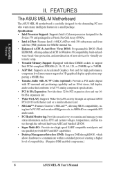
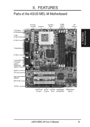
II. FEATURES Motherboard Parts II. FEATURES Parts of the ASUS MEL-M Motherboard T: PS/2 Mouse B: PS/2 Keyboard T: USB 1 B: USB 2 B: COM 1 T: Parallel/Printer B: COM 2 T: Joystick/Midi B: Out/In/Mic (optional) Yamaha Audio (optional) AGP Port 3 PCI Slots Audio Codec (optional) Multi-I/O Chip 1 ISA Slot ATX Power Connector Socket 370 Intel 440LX AGPset 3 DIMM Sockets DIP Switches Wake-On-LAN SB-LinkTM Intel PIIX4 Programmable Hardware Monitor Connector Connector PCIset Flash EEPROM (optional) ASUS MEL-M User's Manual 11
II. FEATURES Motherboard Parts II. FEATURES Parts of the ASUS MEL-M Motherboard T: PS/2 Mouse B: PS/2 Keyboard T: USB 1 B: USB 2 B: COM 1 T: Parallel/Printer B: COM 2 T: Joystick/Midi B: Out/In/Mic (optional) Yamaha Audio (optional) AGP Port 3 PCI Slots Audio Codec (optional) Multi-I/O Chip 1 ISA Slot ATX Power Connector Socket 370 Intel 440LX AGPset 3 DIMM Sockets DIP Switches Wake-On-LAN SB-LinkTM Intel PIIX4 Programmable Hardware Monitor Connector Connector PCIset Flash EEPROM (optional) ASUS MEL-M User's Manual 11
MEL-M User Manual
Page 12
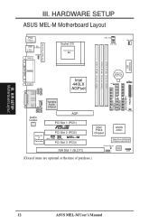
... III. III. HARDWARE SETUP ASUS MEL-M Motherboard Layout PS/2 T: Mouse B: Keyboard USB T: Port 1 B: Port 2 T: Top B: Bottom COM1 KBPWR Socket 370 Thermal Sensor 01 01 01 PWR_FAN CPU_FAN CHA_FAN PARALLEL PORT ATX Power ... Yamaha Audio Chipset In Mic Audio Codec AGP PCI Slot 1 (PCI1) R Multi-I/O & Keyboard Controller PCI Slot 2 (PCI2) MEL-M WOL_CON SBLINK PCI Slot 3 (PCI3) ISA Slot 1 (SLOT1) 01 23 45 IDELED Intel PIIX4 Chipset ASUS ASIC 2Mbit Flash EEPROM (Programmable BIOS) Thermal Sensor CHASIS Hardware Monitor SMB (Grayed items are optional at the...
... III. III. HARDWARE SETUP ASUS MEL-M Motherboard Layout PS/2 T: Mouse B: Keyboard USB T: Port 1 B: Port 2 T: Top B: Bottom COM1 KBPWR Socket 370 Thermal Sensor 01 01 01 PWR_FAN CPU_FAN CHA_FAN PARALLEL PORT ATX Power ... Yamaha Audio Chipset In Mic Audio Codec AGP PCI Slot 1 (PCI1) R Multi-I/O & Keyboard Controller PCI Slot 2 (PCI2) MEL-M WOL_CON SBLINK PCI Slot 3 (PCI3) ISA Slot 1 (SLOT1) 01 23 45 IDELED Intel PIIX4 Chipset ASUS ASIC 2Mbit Flash EEPROM (Programmable BIOS) Thermal Sensor CHASIS Hardware Monitor SMB (Grayed items are optional at the...

MEL-M User Manual
Page 13
H/W SETUP Layout Contents III. ASUS MEL-M User's Manual 13 HARDWARE SETUP Motherboard Settings 1) KBPWR 2) DIP-Switch 5 3) DIP-Switch 6 4) DIP-Switch 1,2,3,4 5) DIP-Switch 7,8,9,10 p. 14 Keyboard Power Up (Enable/Disable) p. 15 Onboard Audio Setting p. 15 VIO Setting p. 16 ...
H/W SETUP Layout Contents III. ASUS MEL-M User's Manual 13 HARDWARE SETUP Motherboard Settings 1) KBPWR 2) DIP-Switch 5 3) DIP-Switch 6 4) DIP-Switch 1,2,3,4 5) DIP-Switch 7,8,9,10 p. 14 Keyboard Power Up (Enable/Disable) p. 15 Onboard Audio Setting p. 15 VIO Setting p. 16 ...

MEL-M User Manual
Page 14
... Disable because not all computers have the right ATX power supply. 01 01 01 R MEL-M MEL-M Keyboard Power Up KBPWR 3 2 1 Disable (Default) KBPWR 3 2 1 Enable 14 ASUS MEL-M User's Manual Use a grounded wrist strap before handling computer components. Install Memory Modules 3. Check Motherboard Settings 2. To protect them against damage from the system. 1. Set this to a metal...
... Disable because not all computers have the right ATX power supply. 01 01 01 R MEL-M MEL-M Keyboard Power Up KBPWR 3 2 1 Disable (Default) KBPWR 3 2 1 Enable 14 ASUS MEL-M User's Manual Use a grounded wrist strap before handling computer components. Install Memory Modules 3. Check Motherboard Settings 2. To protect them against damage from the system. 1. Set this to a metal...

MEL-M User Manual
Page 15
R MEL-M MEL-M DIP Switches 01 01 01 ON 1 2 3 4 5 6 7 8 9 10 OFF ON HARDWARE SETUP Motherboard Settings (DIP Switches) Some of the motherboard's onboard functions can be adjusted through the DIP switches. The white block represents the switch's position. III. The example below shows all the switches in the OFF position.
R MEL-M MEL-M DIP Switches 01 01 01 ON 1 2 3 4 5 6 7 8 9 10 OFF ON HARDWARE SETUP Motherboard Settings (DIP Switches) Some of the motherboard's onboard functions can be adjusted through the DIP switches. The white block represents the switch's position. III. The example below shows all the switches in the OFF position.
MEL-M User Manual
Page 16
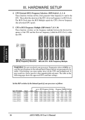
... [ON] 5.0x 66MHz [OFF] [OFF] [OFF] [OFF] [ON] [OFF] [OFF] [ON] 4.5x 66MHz [OFF] [OFF] [OFF] [OFF] [OFF] [ON] [OFF] [ON] 16 ASUS MEL-M User's Manual Frequencies above 66MHz exceed the specifications for the onboard Intel Chipset and are not guaranteed to BUS Frequency Multiple (DIP-Switch 7, 8, 9, 10) These... what frequency to send to the CPU. HARDWARE SETUP 4. The table on the CPU and motherboard. III. Set the DIP switches by the Internal speed of your processor. H/W SETUP Motherboard Settings III. The BUS Clock times the BUS Multiple equals the CPU's Internal frequency (the...
... [ON] 5.0x 66MHz [OFF] [OFF] [OFF] [OFF] [ON] [OFF] [OFF] [ON] 4.5x 66MHz [OFF] [OFF] [OFF] [OFF] [OFF] [ON] [OFF] [ON] 16 ASUS MEL-M User's Manual Frequencies above 66MHz exceed the specifications for the onboard Intel Chipset and are not guaranteed to BUS Frequency Multiple (DIP-Switch 7, 8, 9, 10) These... what frequency to send to the CPU. HARDWARE SETUP 4. The table on the CPU and motherboard. III. Set the DIP switches by the Internal speed of your processor. H/W SETUP Motherboard Settings III. The BUS Clock times the BUS Multiple equals the CPU's Internal frequency (the...
MEL-M User Manual
Page 17
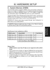
... IMPORTANT: Memory speed setup is required through "Auto Configuration" in BIOS Chipset Setup of either 8, 16, 32, 64, 128MB, or 256MB. ASUS MEL-M User's Manual 17 WARNING! Memory modules with this mother- H/W SETUP System Memory III. System Memory (DIMM) Only Dual Inline Memory Modules (...DIMM) can be used with more than EDO chips. • BIOS shows SDRAM memory on this motherboard. board. • Two possible memory modules are supported: SDRAM with and without ECC. • SDRAM chips are generally thinner and have higher...
... IMPORTANT: Memory speed setup is required through "Auto Configuration" in BIOS Chipset Setup of either 8, 16, 32, 64, 128MB, or 256MB. ASUS MEL-M User's Manual 17 WARNING! Memory modules with this mother- H/W SETUP System Memory III. System Memory (DIMM) Only Dual Inline Memory Modules (...DIMM) can be used with more than EDO chips. • BIOS shows SDRAM memory on this motherboard. board. • Two possible memory modules are supported: SDRAM with and without ECC. • SDRAM chips are generally thinner and have higher...
MEL-M User Manual
Page 18
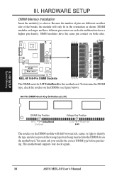
... each side and therefore have a higher pin density. This motherboard supports four clock signals. 18 ASUS MEL-M User's Manual SIMM modules have different pin contact on either side of pins are longer and have the same pin contact on the motherboard. H/W SETUP System Memory R MEL-M MEL-M 168-Pin DIMM Sockets The DIMMs must ask your retailer...
... each side and therefore have a higher pin density. This motherboard supports four clock signals. 18 ASUS MEL-M User's Manual SIMM modules have different pin contact on either side of pins are longer and have the same pin contact on the motherboard. H/W SETUP System Memory R MEL-M MEL-M 168-Pin DIMM Sockets The DIMMs must ask your retailer...
MEL-M User Manual
Page 19
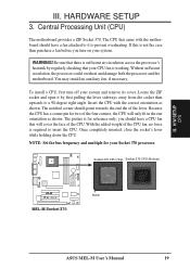
... right angle. NOTE: Set the bus frequency and multiple for reference only; H/W SETUP CPU III. HARDWARE SETUP 3. Central Processing Unit (CPU) The motherboard provides a ZIF Socket 370. Be sure that will cover the face of the four corners, the CPU will only fit in the one orientation as... shown. Socket 370 CPU (Top) Socket 370 CPU (Bottom) 01 01 01 R MEL-M MEL-M Socket 370 Notch ASUS MEL-M User's Manual 19 The notched corner should have a fan attached to it by regularly checking that came with the correct orientation as shown...
... right angle. NOTE: Set the bus frequency and multiple for reference only; H/W SETUP CPU III. HARDWARE SETUP 3. Central Processing Unit (CPU) The motherboard provides a ZIF Socket 370. Be sure that will cover the face of the four corners, the CPU will only fit in the one orientation as... shown. Socket 370 CPU (Top) Socket 370 CPU (Bottom) 01 01 01 R MEL-M MEL-M Socket 370 Notch ASUS MEL-M User's Manual 19 The notched corner should have a fan attached to it by regularly checking that came with the correct orientation as shown...

MEL-M User Manual
Page 21
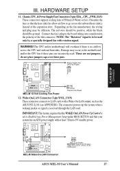
... the Resources tab under the Control Panel program). You may use the Microsoft Diagnostics (MSD.EXE) utility located in PNP AND PCI SETUP) 7. ASUS MEL-M User's Manual 21 HARDWARE SETUP 4. Read the documentation for your expansion card, such as IRQ xx Used By ISA: Yes in the Windows ...that you use , leaving 6 IRQs free for your expansion card and make any available slot on the slot with the screw you unplug your motherboard and expansion cards. NOTE: The onboard audio by a particular device (to gain access, double-click the System icon under Device Manager displays the...
... the Resources tab under the Control Panel program). You may use the Microsoft Diagnostics (MSD.EXE) utility located in PNP AND PCI SETUP) 7. ASUS MEL-M User's Manual 21 HARDWARE SETUP 4. Read the documentation for your expansion card, such as IRQ xx Used By ISA: Yes in the Windows ...that you use , leaving 6 IRQs free for your expansion card and make any available slot on the slot with the screw you unplug your motherboard and expansion cards. NOTE: The onboard audio by a particular device (to gain access, double-click the System icon under Device Manager displays the...
MEL-M User Manual
Page 22
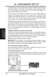
... SETUP To simplify this process this motherboard are set something called the INT (interrupt) assignment. Since all the PCI slots on your vendor for those available. III. H/W SETUP Expansion Cards 01 01 01 R MEL-M MEL-M Accelerated Graphics Port (AGP) 22 ASUS MEL-M User's Manual For PNP cards,... setup utility can contact your PCI cards are handled the same way as an ASUS 3D hardware accelerator. An IRQ number is added to reserve). Assigning DMA Channels for this motherboard has complied with the BIOS, you want to the system. Accelerated Graphics Port ...
... SETUP To simplify this process this motherboard are set something called the INT (interrupt) assignment. Since all the PCI slots on your vendor for those available. III. H/W SETUP Expansion Cards 01 01 01 R MEL-M MEL-M Accelerated Graphics Port (AGP) 22 ASUS MEL-M User's Manual For PNP cards,... setup utility can contact your PCI cards are handled the same way as an ASUS 3D hardware accelerator. An IRQ number is added to reserve). Assigning DMA Channels for this motherboard has complied with the BIOS, you want to the system. Accelerated Graphics Port ...
MEL-M User Manual
Page 23
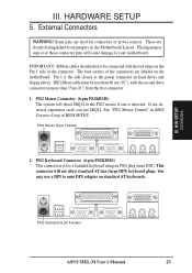
...SETUP DCMoAnnCehcatnornsels PS/2 Keyboard (6-pin Female) ASUS MEL-M User's Manual 23 See "PS/2 Mouse Control" in the Motherboard Layout. IDE ribbon cable must be connected with the second drive connector no more than 46 cm (18"), with the red stripe on the motherboard. PS/2 Keyboard Connector (6-pin PS2KBMS) This...PS/2 mouse if one is for connectors or power sources. PS/2 Mouse Connector (6-pin PS2KBMS) The system will direct IRQ12 to your motherboard. If not detected, expansion cards can use a DIN to the power connector on standard AT keyboards. Pin 1 is the side ...
...SETUP DCMoAnnCehcatnornsels PS/2 Keyboard (6-pin Female) ASUS MEL-M User's Manual 23 See "PS/2 Mouse Control" in the Motherboard Layout. IDE ribbon cable must be connected with the second drive connector no more than 46 cm (18"), with the red stripe on the motherboard. PS/2 Keyboard Connector (6-pin PS2KBMS) This...PS/2 mouse if one is for connectors or power sources. PS/2 Mouse Connector (6-pin PS2KBMS) The system will direct IRQ12 to your motherboard. If not detected, expansion cards can use a DIN to the power connector on standard AT keyboards. Pin 1 is the side ...
MEL-M User Manual
Page 27
...may be different. The connector powers up the system when a wakeup packet or signal is set to Enabled (see APPENDIX). The CPU and/or motherboard will overheat if there is to go across the CPU and onboard heatsinks. Power Supply Fan CPU Fan Power Rotation +12V GND III. H/W SETUP ... IMPORTANT: Requires an ATX power supply with at least 720mA +5-volt standby power ASUS MEL-M User's Manual 27 WARNING! These are incorrectly used only by a specially designed fan with a Wake-On-LAN output, such as the ASUS PCI-L101 (see Power Management Setup under BIOS SETUP) and that the heat ...
...may be different. The connector powers up the system when a wakeup packet or signal is set to Enabled (see APPENDIX). The CPU and/or motherboard will overheat if there is to go across the CPU and onboard heatsinks. Power Supply Fan CPU Fan Power Rotation +12V GND III. H/W SETUP ... IMPORTANT: Requires an ATX power supply with at least 720mA +5-volt standby power ASUS MEL-M User's Manual 27 WARNING! These are incorrectly used only by a specially designed fan with a Wake-On-LAN output, such as the ASUS PCI-L101 (see Power Management Setup under BIOS SETUP) and that the heat ...

MEL-M User Manual
Page 28
... and receiving infrared module. This module mounts to a small opening on the Back View and connect a ribbon cable from the module to the motherboard according to select whether UART2 is directed for use with COM2 or IrDA. Hard Disk Activity LED (2-pin IDELED) This connector supplies power to ...light up. IDELED 28 ASUS MEL-M User's Manual Read and write activity by devices connected to the Primary or Secondary IDE connectors will cause the LED to the cabinet's hard ...
... and receiving infrared module. This module mounts to a small opening on the Back View and connect a ribbon cable from the module to the motherboard according to select whether UART2 is directed for use with COM2 or IrDA. Hard Disk Activity LED (2-pin IDELED) This connector supplies power to ...light up. IDELED 28 ASUS MEL-M User's Manual Read and write activity by devices connected to the Primary or Secondary IDE connectors will cause the LED to the cabinet's hard ...


