
MEL-C User Manual
Page 1
R MEL-C Socket 370 Motherboard USER'S MANUAL
R MEL-C Socket 370 Motherboard USER'S MANUAL

MEL-C User Manual
Page 4
... DIMM Memory Installation 18 3. Central Processing Unit (CPU 19 4. CONTENTS I. HARDWARE SETUP 12 ASUS MEL-C Motherboard Layout 12 Hardware Setup Steps 14 1. FEATURES 8 The ASUS MEL-C Motherboard 8 Parts of PNP and PCI Setup 50 Load BIOS Defaults 52 Load Setup Defaults 52 4 ASUS MEL-C User's Manual Motherboard Settings 14 2. BIOS SETUP 34 Main Menu 34 Managing and Updating Your...
... DIMM Memory Installation 18 3. Central Processing Unit (CPU 19 4. CONTENTS I. HARDWARE SETUP 12 ASUS MEL-C Motherboard Layout 12 Hardware Setup Steps 14 1. FEATURES 8 The ASUS MEL-C Motherboard 8 Parts of PNP and PCI Setup 50 Load BIOS Defaults 52 Load Setup Defaults 52 4 ASUS MEL-C User's Manual Motherboard Settings 14 2. BIOS SETUP 34 Main Menu 34 Managing and Updating Your...
MEL-C User Manual
Page 6
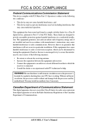
... the Radio Interference Regulations of the Canadian Department of Communications. 6 ASUS MEL-C User's Manual This equipment has been tested and found to comply with FCC Rules Part 15. Without sufficient circulation, the processor could overheat and damage both the processor and the motherboard. WARNING! These limits are designed to Part 15 of the...
... the Radio Interference Regulations of the Canadian Department of Communications. 6 ASUS MEL-C User's Manual This equipment has been tested and found to comply with FCC Rules Part 15. Without sufficient circulation, the processor could overheat and damage both the processor and the motherboard. WARNING! These limits are designed to Part 15 of the...
MEL-C User Manual
Page 7
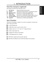
...Manual information and checklist II. BIOS Setup Instructions on available optional hardware Item Checklist Check that your retailer. (1) ASUS Motherboard (1) IDE ribbon cable for master and slave drives (1) Ribbon cable for the included support software VII. Software Setup Instructions ...Bag of spare jumper caps (1) Support CD with drivers and utilities (1) This Motherboard User's Manual ASUS IrDA-compliant infrared module (optional) ASUS PCI-L101 Wake-On-LAN 10/100 Fast Ethernet Card (optional) ASUS MEL-C User's Manual 7 INTRODUCTION How this product III. If you discover damaged ...
...Manual information and checklist II. BIOS Setup Instructions on available optional hardware Item Checklist Check that your retailer. (1) ASUS Motherboard (1) IDE ribbon cable for master and slave drives (1) Ribbon cable for the included support software VII. Software Setup Instructions ...Bag of spare jumper caps (1) Support CD with drivers and utilities (1) This Motherboard User's Manual ASUS IrDA-compliant infrared module (optional) ASUS PCI-L101 Wake-On-LAN 10/100 Fast Ethernet Card (optional) ASUS MEL-C User's Manual 7 INTRODUCTION How this product III. If you discover damaged ...

MEL-C User Manual
Page 8
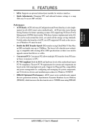
... to communicate within a standard protocol creating a higher level of hard drives, expansion cards, and other devices virtually automatic. 8 ASUS MEL-C User's Manual II. Specifications: • Intel Processor Support: Supports Intel Celeron processors (300MHz and faster) designed for the ... PCI Bus Master IDE controller with two connectors that support four IDE devices in a small package. FEATURES The ASUS MEL-C Motherboard The ASUS MEL-C motherboard is carefully designed for high performance, component level interconnect targeted at 3D graphical display applications supporting a 1X or...
... to communicate within a standard protocol creating a higher level of hard drives, expansion cards, and other devices virtually automatic. 8 ASUS MEL-C User's Manual II. Specifications: • Intel Processor Support: Supports Intel Celeron processors (300MHz and faster) designed for the ... PCI Bus Master IDE controller with two connectors that support four IDE devices in a small package. FEATURES The ASUS MEL-C Motherboard The ASUS MEL-C motherboard is carefully designed for high performance, component level interconnect targeted at 3D graphical display applications supporting a 1X or...
MEL-C User Manual
Page 9
...high-level goals: Support for Plug and Play compatibility and power management for Windows 95/98/NT. • SDRAM Optimized Performance: ASUS smart series motherboards support the new generation memory, Synchronous Dynamic Random Access Memory (SDRAM), which increases the data transfer rate to CPU. • ... also imple- II. To fully utilize the benefits of ACPI, an ACPI-supported OS such as the successor of the motherboard meets PC'98 compliancy. ASUS MEL-C User's Manual 9 The new PC'98 requirements for systems and components are based on all the energy saving standards. ...
...high-level goals: Support for Plug and Play compatibility and power management for Windows 95/98/NT. • SDRAM Optimized Performance: ASUS smart series motherboards support the new generation memory, Synchronous Dynamic Random Access Memory (SDRAM), which increases the data transfer rate to CPU. • ... also imple- II. To fully utilize the benefits of ACPI, an ACPI-supported OS such as the successor of the motherboard meets PC'98 compliancy. ASUS MEL-C User's Manual 9 The new PC'98 requirements for systems and components are based on all the energy saving standards. ...

MEL-C User Manual
Page 11
II. FEATURES Parts of the ASUS MEL-C Motherboard T: PS/2 Mouse B: PS/2 Keyboard T: USB 1 B: USB 2 B: COM 1 T: Parallel/Printer B: Serial Ports B: COM 2 T: Joystick/Midi B: Out/In/Mic (Optional) ESS Solo-1 Audio (Optional) AGP Port Multi-I/O Chip Programmable Flash EEPROM 4 PCI Slots ATX Power Connector Socket 370 Intel 440LX AGPset 3 DIMM Sockets IDE1 & 2 2 ISA Slots SB-LinkTM Wake-On-LAN Connector Connector Intel PIIX4 PCIset Wake-On-Ring DIP Connector Switches ASUS MEL-C User's Manual 11 FEATURES Motherboard Parts II.
II. FEATURES Parts of the ASUS MEL-C Motherboard T: PS/2 Mouse B: PS/2 Keyboard T: USB 1 B: USB 2 B: COM 1 T: Parallel/Printer B: Serial Ports B: COM 2 T: Joystick/Midi B: Out/In/Mic (Optional) ESS Solo-1 Audio (Optional) AGP Port Multi-I/O Chip Programmable Flash EEPROM 4 PCI Slots ATX Power Connector Socket 370 Intel 440LX AGPset 3 DIMM Sockets IDE1 & 2 2 ISA Slots SB-LinkTM Wake-On-LAN Connector Connector Intel PIIX4 PCIset Wake-On-Ring DIP Connector Switches ASUS MEL-C User's Manual 11 FEATURES Motherboard Parts II.

MEL-C User Manual
Page 12
HARDWARE SETUP ASUS MEL-C Motherboard Layout PS/2 T: Mouse B: Keyboard USB T: Port 1 B: Port 2 Socket 370 CPU_FAN PWR_FAN COM1 SECONDARY IDE DIMM Socket 1 (64/72 bit, 168 pin module) DIMM Socket 2 (64/72 bit, 168 pin module) DIMM Socket 3 (64/72 bit, 168 pin module) PARALLEL PORT KBPWR ATX Power Conenctor PRIMARY IDE III. H/W SETUP Motherboard Layout... PIIX4 Chipset CHA_FAN DIP Switches WOR CR2032 3V Lithium Cell CMOS Power IR IDELED PANEL (Grayed items are optional at the time of purchase.) 12 ASUS MEL-C User's Manual III.
HARDWARE SETUP ASUS MEL-C Motherboard Layout PS/2 T: Mouse B: Keyboard USB T: Port 1 B: Port 2 Socket 370 CPU_FAN PWR_FAN COM1 SECONDARY IDE DIMM Socket 1 (64/72 bit, 168 pin module) DIMM Socket 2 (64/72 bit, 168 pin module) DIMM Socket 3 (64/72 bit, 168 pin module) PARALLEL PORT KBPWR ATX Power Conenctor PRIMARY IDE III. H/W SETUP Motherboard Layout... PIIX4 Chipset CHA_FAN DIP Switches WOR CR2032 3V Lithium Cell CMOS Power IR IDELED PANEL (Grayed items are optional at the time of purchase.) 12 ASUS MEL-C User's Manual III.

MEL-C User Manual
Page 13
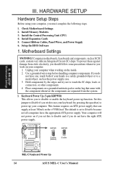
H/W SETUP Layout Contents III. III. HARDWARE SETUP Motherboard Settings 1) KBPWR 2) DIP5 3) DIP6 4) DIP1,2,3 5) DIP7,8,9,10 p. 14 Keyboard Power Up (Enable/Disable) p. 15 Onboard Audio Setting p. 15 VIO Setting p. 16 CPU Bus Frequency p. 16 ... (PANEL) p. 31 System Power LED Lead (3-1 pins) 25) KEYLOCK (PANEL) p. 31 Keyboard Lock Switch Lead (2 pins) 26) SPEAKER (PANEL) p. 31 System Warning Speaker Connector (4 pins) ASUS MEL-C User's Manual 13
H/W SETUP Layout Contents III. III. HARDWARE SETUP Motherboard Settings 1) KBPWR 2) DIP5 3) DIP6 4) DIP1,2,3 5) DIP7,8,9,10 p. 14 Keyboard Power Up (Enable/Disable) p. 15 Onboard Audio Setting p. 15 VIO Setting p. 16 CPU Bus Frequency p. 16 ... (PANEL) p. 31 System Power LED Lead (3-1 pins) 25) KEYLOCK (PANEL) p. 31 Keyboard Lock Switch Lead (2 pins) 26) SPEAKER (PANEL) p. 31 System Warning Speaker Connector (4 pins) ASUS MEL-C User's Manual 13
MEL-C User Manual
Page 14
... and if you must complete the following steps: 1. Use a grounded wrist strap before handling computer components. KBPWR 3 2 1 Disable (Default) KBPWR 3 2 1 Enable MEL-C Keyboard Power Up 14 ASUS MEL-C User's Manual H/W SETUP Motherboard Settings III. HARDWARE SETUP Hardware Setup Steps Before using your computer when working on the +5VSB lead. Install Expansion Cards 5. Connect Ribbon...
... and if you must complete the following steps: 1. Use a grounded wrist strap before handling computer components. KBPWR 3 2 1 Disable (Default) KBPWR 3 2 1 Enable MEL-C Keyboard Power Up 14 ASUS MEL-C User's Manual H/W SETUP Motherboard Settings III. HARDWARE SETUP Hardware Setup Steps Before using your computer when working on the +5VSB lead. Install Expansion Cards 5. Connect Ribbon...

MEL-C User Manual
Page 15
HARDWARE SETUP Motherboard Feature Settings (DIP Switches) The motherboard's onboard features can be adjusted through the DIP switches. The white block represents the switch's position. OFF ON ON 1 2 3 4 5 6 7 8 9 10 MEL-C DIP Switch The example below shows all the switches in the OFF position. III.
HARDWARE SETUP Motherboard Feature Settings (DIP Switches) The motherboard's onboard features can be adjusted through the DIP switches. The white block represents the switch's position. OFF ON ON 1 2 3 4 5 6 7 8 9 10 MEL-C DIP Switch The example below shows all the switches in the OFF position. III.

MEL-C User Manual
Page 16
... [ON] [OFF] [OFF] [ON] [ON] [OFF] [ON] [ON] [ON] [OFF] [OFF] [OFF] [OFF] [ON] [ON] [OFF] [OFF] [ON] [OFF] [ON] [OFF] [ON] 16 ASUS MEL-C User's Manual vertised CPU speed). III. CPU External (BUS) Frequency Selection (DIP1, 2, 3) These DIP switches tell the clock generator what frequency to send to BUS...3 4 5 6 7 8 9 10 ON 1 2 3 4 5 6 7 8 9 10 ON 1 2 3 4 5 6 7 8 9 10 ON 1 2 3 4 5 6 7 8 9 10 III. The BUS Clock times the BUS Ratio equals the CPU's Internal frequency (the ad- H/W SETUP Motherboard Settings MEL-C CPU BUS Frequency Selection 5. HARDWARE SETUP 4. CPU to the CPU.
... [ON] [OFF] [OFF] [ON] [ON] [OFF] [ON] [ON] [ON] [OFF] [OFF] [OFF] [OFF] [ON] [ON] [OFF] [OFF] [ON] [OFF] [ON] [OFF] [ON] 16 ASUS MEL-C User's Manual vertised CPU speed). III. CPU External (BUS) Frequency Selection (DIP1, 2, 3) These DIP switches tell the clock generator what frequency to send to BUS...3 4 5 6 7 8 9 10 ON 1 2 3 4 5 6 7 8 9 10 ON 1 2 3 4 5 6 7 8 9 10 ON 1 2 3 4 5 6 7 8 9 10 III. The BUS Clock times the BUS Ratio equals the CPU's Internal frequency (the ad- H/W SETUP Motherboard Settings MEL-C CPU BUS Frequency Selection 5. HARDWARE SETUP 4. CPU to the CPU.

MEL-C User Manual
Page 17
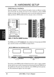
... 9 chips/side modules support ECC. • Single-sided DIMMs come in BIOS SETUP. This motherboard uses only Dual Inline Memory Modules (DIMMs). One side (with higher pin density than 18 chips exceed specifications and may cause unstable operation. ASUS MEL-C User's Manual 17 H/W SETUP System Memory III. Sockets are generally thinner with memory... Random Access Memory (SDRAM) of either 8, 16, 32, 64, 128MB, or 256MB. HARDWARE SETUP 2. tended Data Output) chips. • BIOS shows SDRAM memory on the motherboard.
... 9 chips/side modules support ECC. • Single-sided DIMMs come in BIOS SETUP. This motherboard uses only Dual Inline Memory Modules (DIMMs). One side (with higher pin density than 18 chips exceed specifications and may cause unstable operation. ASUS MEL-C User's Manual 17 H/W SETUP System Memory III. Sockets are generally thinner with memory... Random Access Memory (SDRAM) of either 8, 16, 32, 64, 128MB, or 256MB. HARDWARE SETUP 2. tended Data Output) chips. • BIOS shows SDRAM memory on the motherboard.
MEL-C User Manual
Page 18
...DIMM slot on both sides. DIMM modules are different on each side and therefore have the same pin contact on the motherboard. To determine the DIMM type, check the notches on the DIMMs (see figure below). 168-Pin DIMM Notch Key ...motherboard. HARDWARE SETUP DIMM Memory Installation Insert the module(s) as shown. SIMM modules have a higher pin density. Lock 20 Pins 60 Pins 88 Pins FRONT III. H/W SETUP System Memory MEL-C 168-Pin DIMM Sockets The DIMMs must ask your retailer the correct DIMM type before purchasing. This motherboard supports four clock signals. 18 ASUS MEL...
...DIMM slot on both sides. DIMM modules are different on each side and therefore have the same pin contact on the motherboard. To determine the DIMM type, check the notches on the DIMMs (see figure below). 168-Pin DIMM Notch Key ...motherboard. HARDWARE SETUP DIMM Memory Installation Insert the module(s) as shown. SIMM modules have a higher pin density. Lock 20 Pins 60 Pins 88 Pins FRONT III. H/W SETUP System Memory MEL-C 168-Pin DIMM Sockets The DIMMs must ask your retailer the correct DIMM type before purchasing. This motherboard supports four clock signals. 18 ASUS MEL...

MEL-C User Manual
Page 19
...'s lever while holding down the CPU. Socket 370 CPU (Top) Socket 370 CPU (Bottom) III. Central Processing Unit (CPU) The motherboard provides a ZIF Socket 370. Be sure that there is sufficient air circulation across the processor's heatsink by first pulling the lever sideways away... socket and open it to a 90-degree right angle. H/W SETUP CPU Notch MEL-C Socket 370 ASUS MEL-C User's Manual 19 Without sufficient circulation, the processor could overheat and damage both the processor and the motherboard. NOTE: Set the bus frequency and multiple for reference only; If this is...
...'s lever while holding down the CPU. Socket 370 CPU (Top) Socket 370 CPU (Bottom) III. Central Processing Unit (CPU) The motherboard provides a ZIF Socket 370. Be sure that there is sufficient air circulation across the processor's heatsink by first pulling the lever sideways away... socket and open it to a 90-degree right angle. H/W SETUP CPU Notch MEL-C Socket 370 ASUS MEL-C User's Manual 19 Without sufficient circulation, the processor could overheat and damage both the processor and the motherboard. NOTE: Set the bus frequency and multiple for reference only; If this is...
MEL-C User Manual
Page 21
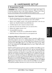
... expansion cards may require to use IRQs. Ensure that no two devices share the same IRQs or your motherboard has PCI audio onboard, an extra IRQ will be used and free IRQs. Secure the card on the slot ...bracket for expansion cards. In a standard design, there are 16 IRQs available but most of them are two types of your motherboard and expansion cards. III. HARDWARE SETUP 4. H/W SETUP Expansion Cards III. Failure to cards installed in PNP AND PCI SETUP)... of ISA cards. Currently, there are already in the Windows directory to operate. ASUS MEL-C User's Manual 21
... expansion cards may require to use IRQs. Ensure that no two devices share the same IRQs or your motherboard has PCI audio onboard, an extra IRQ will be used and free IRQs. Secure the card on the slot ...bracket for expansion cards. In a standard design, there are 16 IRQs available but most of them are two types of your motherboard and expansion cards. III. HARDWARE SETUP 4. H/W SETUP Expansion Cards III. Failure to cards installed in PNP AND PCI SETUP)... of ISA cards. Currently, there are already in the Windows directory to operate. ASUS MEL-C User's Manual 21
MEL-C User Manual
Page 22
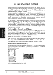
... H/W SETUP Expansion Cards MEL-C Accelerated Graphics Port (AGP) 22 ASUS MEL-C User's Manual An IRQ number is added to reserve). You can contact your PCI cards are handled the same way as an ASUS 3D hardware accelerator. Accelerated Graphics Port (AGP) This motherboard provides an accelerated graphics ...port (AGP) slot to a PCI slot that requires an IRQ. For older Legacy cards that the jumpers on this motherboard has complied with ultra-high ...
... H/W SETUP Expansion Cards MEL-C Accelerated Graphics Port (AGP) 22 ASUS MEL-C User's Manual An IRQ number is added to reserve). You can contact your PCI cards are handled the same way as an ASUS 3D hardware accelerator. Accelerated Graphics Port (AGP) This motherboard provides an accelerated graphics ...port (AGP) slot to a PCI slot that requires an IRQ. For older Legacy cards that the jumpers on this motherboard has complied with ultra-high ...
MEL-C User Manual
Page 23
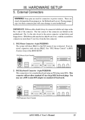
.... You may use IRQ12. III. IMPORTANT: Ribbon cables should always be less than 46 cm(18 in.), with the red stripe on the motherboard. Pin 1 is the side closest to the PS/2 mouse if one is for connectors or power sources. PS/2 Mouse (6-pin Female) 2....on standard AT keyboards. HARDWARE SETUP 5. External Connectors WARNING! If not detected, expansion cards can use a DIN to your motherboard. H/W SETUP Connectors PS/2 Keyboard (6-pin Female) ASUS MEL-C User's Manual 23 IDE ribbon cable must be connected with the second drive connector no more than 15 cm (6 in.)...
.... You may use IRQ12. III. IMPORTANT: Ribbon cables should always be less than 46 cm(18 in.), with the red stripe on the motherboard. Pin 1 is the side closest to the PS/2 mouse if one is for connectors or power sources. PS/2 Mouse (6-pin Female) 2....on standard AT keyboards. HARDWARE SETUP 5. External Connectors WARNING! If not detected, expansion cards can use a DIN to your motherboard. H/W SETUP Connectors PS/2 Keyboard (6-pin Female) ASUS MEL-C User's Manual 23 IDE ribbon cable must be connected with the second drive connector no more than 15 cm (6 in.)...
MEL-C User Manual
Page 27
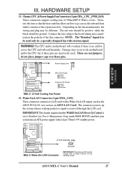
... allow airflow to LAN cards with at least 720mA +5V standby power. +5 Volt Standby PME Ground MEL-C Wake-On-LAN Connector IMPORTANT: Requires an ATX power supply with a Wake-On-LAN output, such as the ASUS PCI-L101 (see section on the fan manufacturer, the wiring and plug may occur to the... SETUP 11. Rotation +12V GND III. Orientate the fans so that your system has an ATX power supply with at least 720mA +5-volt standby power ASUS MEL-C User's Manual 27 Connect the fan's plug to the motherboard and/or the CPU fan if these pins. WARNING! Damage may be ground.
... allow airflow to LAN cards with at least 720mA +5V standby power. +5 Volt Standby PME Ground MEL-C Wake-On-LAN Connector IMPORTANT: Requires an ATX power supply with a Wake-On-LAN output, such as the ASUS PCI-L101 (see section on the fan manufacturer, the wiring and plug may occur to the... SETUP 11. Rotation +12V GND III. Orientate the fans so that your system has an ATX power supply with at least 720mA +5-volt standby power ASUS MEL-C User's Manual 27 Connect the fan's plug to the motherboard and/or the CPU fan if these pins. WARNING! Damage may be ground.
MEL-C User Manual
Page 28
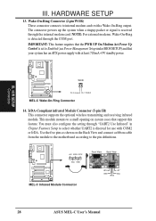
H/W SETUP Connectors WOR Pin 2 Ground Pin 1 PIXRI# MEL-C Wake-On-Ring Connector 14. IMPORTANT: This feature requires that the PWR UP On ... whether UART2 is set to a small opening on the Back View and connect a ribbon cable from the module to the motherboard according to internal modem cards with a Wake-On-Ring output. HARDWARE SETUP 13. The connector powers up the system when ...Ring Connector (2-pin WOR) These connector connects to the pin definitions. +5V IRRX IRTX (NC) GND MEL-C Infrared Module Connector Front View Back View IRTX GND IRRX +5V (NC) 28 ASUS MEL-C User's Manual
H/W SETUP Connectors WOR Pin 2 Ground Pin 1 PIXRI# MEL-C Wake-On-Ring Connector 14. IMPORTANT: This feature requires that the PWR UP On ... whether UART2 is set to a small opening on the Back View and connect a ribbon cable from the module to the motherboard according to internal modem cards with a Wake-On-Ring output. HARDWARE SETUP 13. The connector powers up the system when ...Ring Connector (2-pin WOR) These connector connects to the pin definitions. +5V IRRX IRTX (NC) GND MEL-C Infrared Module Connector Front View Back View IRTX GND IRRX +5V (NC) 28 ASUS MEL-C User's Manual


