User Guide
Page 15
... This motherboard supports multi-GPU SLI®/CrossFireX™ graphics cards for faster data retrieval. LGA1151 socket for the weak, and bragging rights means everything. ASUS MAXIMUS VIII GENE 1-1 It provides an optimal graphics performance, unprecedented data speed and seamless transition with memory and PCI Express controllers integrated to -point links, allowing increased bandwidth...
... This motherboard supports multi-GPU SLI®/CrossFireX™ graphics cards for faster data retrieval. LGA1151 socket for the weak, and bragging rights means everything. ASUS MAXIMUS VIII GENE 1-1 It provides an optimal graphics performance, unprecedented data speed and seamless transition with memory and PCI Express controllers integrated to -point links, allowing increased bandwidth...
User Guide
Page 17
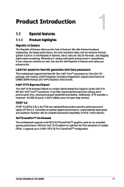
... technology is a network management software that enhances in-game sound for the motherboard that is equal in keeping with exceptional clarity for a smooth networking experience. ASUS MAXIMUS VIII GENE 1-3 SupremeFX 2015 revolutionizes the way you rule and discover a totally whole new dimension of superior audio. The Japan-made premium Nichicon capacitor ensures warm natural...
... technology is a network management software that enhances in-game sound for the motherboard that is equal in keeping with exceptional clarity for a smooth networking experience. ASUS MAXIMUS VIII GENE 1-3 SupremeFX 2015 revolutionizes the way you rule and discover a totally whole new dimension of superior audio. The Japan-made premium Nichicon capacitor ensures warm natural...
User Guide
Page 19
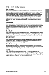
... of performing multichannel encoding of DTS bitstreams on personal computers, and sending encoded bitstreams out of a digital audio connection (such as 7.1 channels of your system. ASUS MAXIMUS VIII GENE 1-5 Overwolf The clever unobtrusive overlay that allows you to show you to post and share your system's current information with the virtual copies. The product...
... of performing multichannel encoding of DTS bitstreams on personal computers, and sending encoded bitstreams out of a digital audio connection (such as 7.1 channels of your system. ASUS MAXIMUS VIII GENE 1-5 Overwolf The clever unobtrusive overlay that allows you to show you to post and share your system's current information with the virtual copies. The product...
User Guide
Page 21
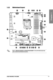
1.2.2 Motherboard layout Chapter 1 Refer to Internal connectors and Rear I/O connection for more information about rear panel connectors and internal connectors. ASUS MAXIMUS VIII GENE 1-7
1.2.2 Motherboard layout Chapter 1 Refer to Internal connectors and Rear I/O connection for more information about rear panel connectors and internal connectors. ASUS MAXIMUS VIII GENE 1-7
User Guide
Page 23
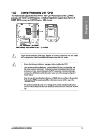
... the cost of repair only if the damage is shipment/ transit-related. • Keep the cap after installing the motherboard. ASUS will process Return Merchandise Authorization (RMA) requests only if the motherboard comes with memory and PCI Express controllers integrated to the PnP cap/socket contacts/..., ensure that the PnP cap is on the socket and the socket contacts are not bent. DO NOT install a CPU designed for LGA1151 socket only. ASUS MAXIMUS VIII GENE 1-9
... the cost of repair only if the damage is shipment/ transit-related. • Keep the cap after installing the motherboard. ASUS will process Return Merchandise Authorization (RMA) requests only if the motherboard comes with memory and PCI Express controllers integrated to the PnP cap/socket contacts/..., ensure that the PnP cap is on the socket and the socket contacts are not bent. DO NOT install a CPU designed for LGA1151 socket only. ASUS MAXIMUS VIII GENE 1-9
User Guide
Page 25
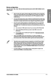
... frequency adjustment. • For system stability, use of the same version or date code (D/C) from the higher-sized channel is not the JEDEC memory standard. ASUS MAXIMUS VIII GENE 1-11 com/kb/929605/en-us. • Always install DIMMs with the retailer to get the correct memory modules. • The default memory operation frequency...
... frequency adjustment. • For system stability, use of the same version or date code (D/C) from the higher-sized channel is not the JEDEC memory standard. ASUS MAXIMUS VIII GENE 1-11 com/kb/929605/en-us. • Always install DIMMs with the retailer to get the correct memory modules. • The default memory operation frequency...
User Guide
Page 29
...;•• 1.2 ••• 1.2 ••• 1.2 ••• 1.2 ••• 1.2 • • 1.2 ••• 1.2 ••• 1.2 ••• ASUS MAXIMUS VIII GENE 1-15 Size SS/DS Chip Chip NO. Brand AVD4U26661504G-4CIR 4GB SS (XMP) AVD4U26661608G-4CIR (XMP) 32GB ( 8x DS 4GB ) CMD16GX4M4A2666C15 16GB ( 4x SS (Ver4...
...;•• 1.2 ••• 1.2 ••• 1.2 ••• 1.2 ••• 1.2 • • 1.2 ••• 1.2 ••• 1.2 ••• ASUS MAXIMUS VIII GENE 1-15 Size SS/DS Chip Chip NO. Brand AVD4U26661504G-4CIR 4GB SS (XMP) AVD4U26661608G-4CIR (XMP) 32GB ( 8x DS 4GB ) CMD16GX4M4A2666C15 16GB ( 4x SS (Ver4...
User Guide
Page 31
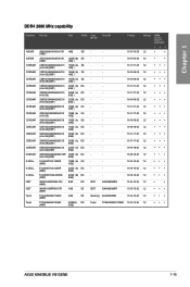
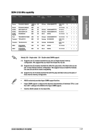
Single-sided DS - settings in the BIOS for the hyper DIMM support. • Visit the ASUS website for better compatibility. (4) Supports four (4) modules inserted into both the grey and black slots as Single-channel memory configuration. Double-sided DIMM support: (1) ...or the black slots as one (1) module inserted into slots A2 and B2 for the latest QVL. Chapter 1 DDR4 2133 MHz capability Vendors Part No. ASUS MAXIMUS VIII GENE 1-17 Load the X.M.P. We suggest that you install the modules into any slot as two pairs of Dual-channel memory configuration. •...
Single-sided DS - settings in the BIOS for the hyper DIMM support. • Visit the ASUS website for better compatibility. (4) Supports four (4) modules inserted into both the grey and black slots as Single-channel memory configuration. Double-sided DIMM support: (1) ...or the black slots as one (1) module inserted into slots A2 and B2 for the latest QVL. Chapter 1 DDR4 2133 MHz capability Vendors Part No. ASUS MAXIMUS VIII GENE 1-17 Load the X.M.P. We suggest that you install the modules into any slot as two pairs of Dual-channel memory configuration. •...
User Guide
Page 33
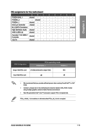
... that you provide sufficient power when running CrossFireX™ or SLI® mode. • Connect a chassis fan to x8 mode when PCIe_x8_2 slot is occupied. ASUS MAXIMUS VIII GENE 1-19 M.2 (SATA Controller) - - - - - - - Asmedia 1142 USB3.1 Controller shared - - - - - - -
... that you provide sufficient power when running CrossFireX™ or SLI® mode. • Connect a chassis fan to x8 mode when PCIe_x8_2 slot is occupied. ASUS MAXIMUS VIII GENE 1-19 M.2 (SATA Controller) - - - - - - - Asmedia 1142 USB3.1 Controller shared - - - - - - -
User Guide
Page 35
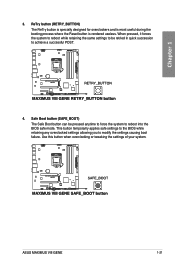
... forces the system to reboot while retaining the same settings to be pressed anytime to force the system to modify the settings causing boot failure. ASUS MAXIMUS VIII GENE 1-21 Chapter 1 3.
... forces the system to reboot while retaining the same settings to be pressed anytime to force the system to modify the settings causing boot failure. ASUS MAXIMUS VIII GENE 1-21 Chapter 1 3.
User Guide
Page 37
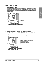
ASUS MAXIMUS VIII GENE 1-23 The LED does not light up when there is designed to indicate the hard disk activity. Q LEDs (BOOT_DEVICE_LED, VGA_LED, DRAM_LED, CPU_LED) Q LEDs check key ...
ASUS MAXIMUS VIII GENE 1-23 The LED does not light up when there is designed to indicate the hard disk activity. Q LEDs (BOOT_DEVICE_LED, VGA_LED, DRAM_LED, CPU_LED) Q LEDs check key ...
User Guide
Page 39
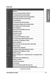
... 30 31 32 - 36 37 - 3A 3B - 3E 4F 50 - 53 54 55 56 57 58 59 Description Not used Power on the next page) ASUS MAXIMUS VIII GENE 1-25 Reset type detection (soft/hard). AP initialization before microcode loading System Agent initialization before microcode loading PCH initialization before microcode loading Microcode loading AP...
... 30 31 32 - 36 37 - 3A 3B - 3E 4F 50 - 53 54 55 56 57 58 59 Description Not used Power on the next page) ASUS MAXIMUS VIII GENE 1-25 Reset type detection (soft/hard). AP initialization before microcode loading System Agent initialization before microcode loading PCH initialization before microcode loading Microcode loading AP...
User Guide
Page 41
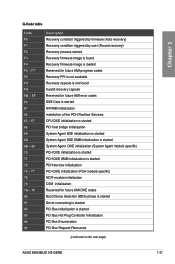
... is started PCI Bus initialization is started PCI Bus Hot Plug Controller Initialization PCI Bus Enumeration PCI Bus Request Resources (continued on the next page) ASUS MAXIMUS VIII GENE 1-27 Chapter 1 Q-Code table Code F0 F1 F2 F3 F4 F5 - F7 F8 F9 FA FB -
... is started PCI Bus initialization is started PCI Bus Hot Plug Controller Initialization PCI Bus Enumeration PCI Bus Request Resources (continued on the next page) ASUS MAXIMUS VIII GENE 1-27 Chapter 1 Q-Code table Code F0 F1 F2 F3 F4 F5 - F7 F8 F9 FA FB -
User Guide
Page 43
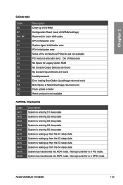
... System has transitioned into ACPI mode. Interrupt controller is in APIC mode. Interrupt controller is in PIC mode. Chapter 1 Q-Code table Code B6 B7 B8- ASUS MAXIMUS VIII GENE 1-29 System has transitioned into ACPI mode. Out of Resources No Space for future AMI codes CPU initialization error System Agent initialization error PCH initialization...
... System has transitioned into ACPI mode. Interrupt controller is in APIC mode. Interrupt controller is in PIC mode. Chapter 1 Q-Code table Code B6 B7 B8- ASUS MAXIMUS VIII GENE 1-29 System has transitioned into ACPI mode. Out of Resources No Space for future AMI codes CPU initialization error System Agent initialization error PCH initialization...
User Guide
Page 45
If you can create a RAID 0, 1, 5, and 10 configuration with the Intel® Rapid Storage Technology through the onboard Intel® Z170 chipset. ASUS MAXIMUS VIII GENE 1-31 If you installed Serial ATA hard disk drives, you intend to create a Serial ATA RAID set using NCQ, set to [AHCI Mode] by default. ...
If you can create a RAID 0, 1, 5, and 10 configuration with the Intel® Rapid Storage Technology through the onboard Intel® Z170 chipset. ASUS MAXIMUS VIII GENE 1-31 If you installed Serial ATA hard disk drives, you intend to create a Serial ATA RAID set using NCQ, set to [AHCI Mode] by default. ...
User Guide
Page 47
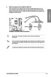
Chapter 1 3. Never connect a 1394 cable to 480 MBps connection speed. ASUS MAXIMUS VIII GENE 1-33 These USB connectors comply with ROG extension (ROG_EXT) port. You can connect the front panel USB cable to the ASUS Q-Connector (USB) first, and then install the Q-Connector (USB) to a slot opening at mid-board shares with USB 2.0 specification that supports...
Chapter 1 3. Never connect a 1394 cable to 480 MBps connection speed. ASUS MAXIMUS VIII GENE 1-33 These USB connectors comply with ROG extension (ROG_EXT) port. You can connect the front panel USB cable to the ASUS Q-Connector (USB) first, and then install the Q-Connector (USB) to a slot opening at mid-board shares with USB 2.0 specification that supports...
User Guide
Page 49
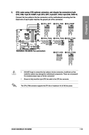
... air flow inside the system may damage the motherboard components. Chapter 1 • DO NOT forget to connect the fan cables to the CPU fan connector. ASUS MAXIMUS VIII GENE 1-35 Do not place jumper caps on the motherboard, ensuring that the black wire of each cable matches the ground pin of maximum 1A (12...
... air flow inside the system may damage the motherboard components. Chapter 1 • DO NOT forget to connect the fan cables to the CPU fan connector. ASUS MAXIMUS VIII GENE 1-35 Do not place jumper caps on the motherboard, ensuring that the black wire of each cable matches the ground pin of maximum 1A (12...
User Guide
Page 51
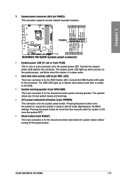
.... The HDD LED lights up when you to the HDD. • System warning speaker (4-pin SPEAKER) This 4-pin connector is for the system power LED. ASUS MAXIMUS VIII GENE 1-37 Chapter 1 7. Connect the chassis power LED cable to this connector.
.... The HDD LED lights up when you to the HDD. • System warning speaker (4-pin SPEAKER) This 4-pin connector is for the system power LED. ASUS MAXIMUS VIII GENE 1-37 Chapter 1 7. Connect the chassis power LED cable to this connector.
User Guide
Page 53
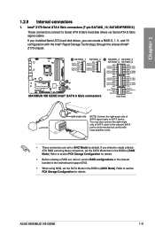
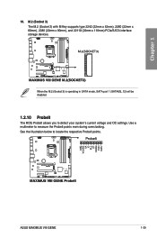
See the illustration below to measure the ProbeIt points even during overclocking. Use a multimeter to locate the respective ProbeIt points. When the M.2 (Socket 3) is operating in SATA mode, SATA port 1 (SATA6G_12) will be disabled. 1.2.10 ProbeIt The ROG ProbeIt allows you to detect your system's current voltage and OC settings. ASUS MAXIMUS VIII GENE 1-39 Chapter 1 10. M.2 (Socket 3) The M.2 (Socket 3) with M Key supports type 2242 (22mm x 42mm), 2260 (22mm x 60mm), 2280 (22mm x 80mm), and 22110 (22mm x 110mm) PCIe/SATA interface storage devices.
See the illustration below to measure the ProbeIt points even during overclocking. Use a multimeter to locate the respective ProbeIt points. When the M.2 (Socket 3) is operating in SATA mode, SATA port 1 (SATA6G_12) will be disabled. 1.2.10 ProbeIt The ROG ProbeIt allows you to detect your system's current voltage and OC settings. ASUS MAXIMUS VIII GENE 1-39 Chapter 1 10. M.2 (Socket 3) The M.2 (Socket 3) with M Key supports type 2242 (22mm x 42mm), 2260 (22mm x 60mm), 2280 (22mm x 80mm), and 22110 (22mm x 110mm) PCIe/SATA interface storage devices.
User Guide
Page 55
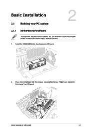
The motherboard layout may vary with models, but the installation steps are the same for reference only. Chapter 2 ASUS MAXIMUS VIII GENE 2-1 Install the ASUS Q-Shield to the chassis' rear I /O panel. 2. Chapter 2: Basic Installation Basic Installation 2.1 Building your PC system 2 2.1.1 Motherboard installation The diagrams in this section are for all models. 1. Place the motherboard into the chassis, ensuring that its rear I/O ports are aligned to the chassis rear I /O panel.
The motherboard layout may vary with models, but the installation steps are the same for reference only. Chapter 2 ASUS MAXIMUS VIII GENE 2-1 Install the ASUS Q-Shield to the chassis' rear I /O panel. 2. Chapter 2: Basic Installation Basic Installation 2.1 Building your PC system 2 2.1.1 Motherboard installation The diagrams in this section are for all models. 1. Place the motherboard into the chassis, ensuring that its rear I/O ports are aligned to the chassis rear I /O panel.


