User Manual
Page 32
Chapter summary 2 2.1 Before you proceed 2-1 2.2 Motherboard overview 2-2 2.3 Building your computer system 2-36 2.4 Starting up for the first time 2-53 2.5 Turning off the computer 2-54 ASUS Maximus IV GENE-Z
Chapter summary 2 2.1 Before you proceed 2-1 2.2 Motherboard overview 2-2 2.3 Building your computer system 2-36 2.4 Starting up for the first time 2-53 2.5 Turning off the computer 2-54 ASUS Maximus IV GENE-Z
User Manual
Page 33
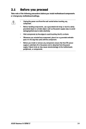
... you install or remove any component, ensure that the ATX power supply is switched off or the power cord is detached from the power supply. ASUS Maximus IV GENE-Z 2-1
... you install or remove any component, ensure that the ATX power supply is switched off or the power cord is detached from the power supply. ASUS Maximus IV GENE-Z 2-1

User Manual
Page 35
...) 12. Reset Switch 14. Digital audio connector (4-1 pin SPDIF_OUT) Page 2-19 2-34 2-4 2-32 2-5 2-19 2-31 2-28 2-29 2-35 2-30 2-22 2-18 2-18 2-27 2-33 2-31 ASUS Maximus IV GENE-Z 2-3 Power connectors (24-pin EATXPWR, 8-pin EATX12V) 3. Clear RTC RAM (3-pin CLRTC_SW) 16. 2.2.2 Layout contents Connectors/Jumpers/Switches/Slots 1. ROG Connect switch 2. LGA1155 CPU Socket...
...) 12. Reset Switch 14. Digital audio connector (4-1 pin SPDIF_OUT) Page 2-19 2-34 2-4 2-32 2-5 2-19 2-31 2-28 2-29 2-35 2-30 2-22 2-18 2-18 2-27 2-33 2-31 ASUS Maximus IV GENE-Z 2-3 Power connectors (24-pin EATXPWR, 8-pin EATX12V) 3. Clear RTC RAM (3-pin CLRTC_SW) 16. 2.2.2 Layout contents Connectors/Jumpers/Switches/Slots 1. ROG Connect switch 2. LGA1155 CPU Socket...
User Manual
Page 37
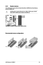
A DDR3 module is notched differently from a DDR or DDR2 module. Recommended memory configurations ASUS Maximus IV GENE-Z 2-5 DO NOT install a DDR or DDR2 memory module to the DDR3 slot. 2.2.4 System memory The motherboard comes with four Double Data Rate 3 (DDR3) Dual Inline Memory Modules (DIMM) slots.
A DDR3 module is notched differently from a DDR or DDR2 module. Recommended memory configurations ASUS Maximus IV GENE-Z 2-5 DO NOT install a DDR or DDR2 memory module to the DDR3 slot. 2.2.4 System memory The motherboard comes with four Double Data Rate 3 (DDR3) Dual Inline Memory Modules (DIMM) slots.
User Manual
Page 39
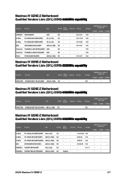
... 1.65 • • • 1.65 • • 1.66 • • • Maximus IV GENE-Z Motherboard Qualified Vendors Lists (QVL) DDR�3�-2���3��3�3��M��H�&#... DS - - 9-10-9-28 1.65 • • • DS - - - 1.5~1.7 • • DS Kingmax - - - • • ASUS Maximus IV GENE-Z 2-7 GEIL GET34GB2400C9DC(XMP) 4GB (2 x 2GB) DS - - Timing CORSAIR CMGTX3(XMP) 2GB DS - - Timing KINGSTON KHX2250C9D3T1K2/4GX(XMP) 4GB (2 x 2GB) ...
... 1.65 • • • 1.65 • • 1.66 • • • Maximus IV GENE-Z Motherboard Qualified Vendors Lists (QVL) DDR�3�-2���3��3�3��M��H�&#... DS - - 9-10-9-28 1.65 • • • DS - - - 1.5~1.7 • • DS Kingmax - - - • • ASUS Maximus IV GENE-Z 2-7 GEIL GET34GB2400C9DC(XMP) 4GB (2 x 2GB) DS - - Timing CORSAIR CMGTX3(XMP) 2GB DS - - Timing KINGSTON KHX2250C9D3T1K2/4GX(XMP) 4GB (2 x 2GB) ...
User Manual
Page 41
...8226; • • • • • • • • • • • • ASUS Maximus IV GENE-Z 2-9 Team TXD32048M2000C9(XMP) 2GB DS Team T3D1288RT-20 9-9-9-24 1.5 Team TXD32048M2000C9-L(XMP) 2GB DS Team T3D1288LT-20 9-9-9-24 1.5 Team TXD32048M2000C9...; • • • • • • • • • • • Maximus IV GENE-Z Motherboard Qualified Vendors Lists (QVL) DDR�3��-�1��8��6�6��M��H��&#...
...8226; • • • • • • • • • • • • ASUS Maximus IV GENE-Z 2-9 Team TXD32048M2000C9(XMP) 2GB DS Team T3D1288RT-20 9-9-9-24 1.5 Team TXD32048M2000C9-L(XMP) 2GB DS Team T3D1288LT-20 9-9-9-24 1.5 Team TXD32048M2000C9...; • • • • • • • • • • • Maximus IV GENE-Z Motherboard Qualified Vendors Lists (QVL) DDR�3��-�1��8��6�6��M��H��&#...

User Manual
Page 43
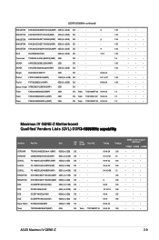
...; • • • • • • • • • • • • • • • • • • • • • • • • • ASUS Maximus IV GENE-Z 2-11 EK Memory EKM324L28BP8-I16(XMP) 4GB (2 x 2GB) DS - - 9 - GoodRam GR1600D364L9/2G 2GB DS GoodRam GF1008KC-JN - - KINGSTON KHX1600C9D3K3/12GX(XMP) 12GB (3 x 4GB) DS N/A - - 1.65...
...; • • • • • • • • • • • • • • • • • • • • • • • • • ASUS Maximus IV GENE-Z 2-11 EK Memory EKM324L28BP8-I16(XMP) 4GB (2 x 2GB) DS - - 9 - GoodRam GR1600D364L9/2G 2GB DS GoodRam GF1008KC-JN - - KINGSTON KHX1600C9D3K3/12GX(XMP) 12GB (3 x 4GB) DS N/A - - 1.65...
User Manual
Page 45
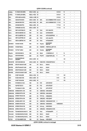
... M378B2873EH1-CH9 1GB SS SAMSUNG K4B1G0846E - - Transcend TS256MLK64V3N (566577) 2GB SS Hynix H5TQ2G83BFR 9 - ACTICA ACT1GHU64B8F1333S 1GB SS Samsung K4B1G0846F - - (DDR3-1333MHz continued on next page) ASUS Maximus IV GENE-Z • • • • • • • • • • • • • • • • • • • • • • • • •...
... M378B2873EH1-CH9 1GB SS SAMSUNG K4B1G0846E - - Transcend TS256MLK64V3N (566577) 2GB SS Hynix H5TQ2G83BFR 9 - ACTICA ACT1GHU64B8F1333S 1GB SS Samsung K4B1G0846F - - (DDR3-1333MHz continued on next page) ASUS Maximus IV GENE-Z • • • • • • • • • • • • • • • • • • • • • • • • •...
User Manual
Page 47
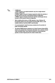
... dual-channel memory configuration. • When installing total memory of 4GB capacity or more, Windows 32bit operating system may operate at a lower frequency than 3GB. ASUS Maximus IV GENE-Z 2-15
... dual-channel memory configuration. • When installing total memory of 4GB capacity or more, Windows 32bit operating system may operate at a lower frequency than 3GB. ASUS Maximus IV GENE-Z 2-15

User Manual
Page 49
EHCI#1 (USB2.0) - - - ASM USB3.0#0 shared - - shared - shared - - SATA #1 - - - JMB362 - - - D E F G H - - - - - - - - - - - - - - - - - - - shared - - - PCIEx16_2 - Intel 82579 - - - ASUS Maximus IV GENE-Z 2-17 shared - - - - shared - - - - - - - - - - - - - - - - shared - - - - - - - - shared - shared - - - - I.G.D shared - - shared - ASM USB3.0#1 - PCIEx4 - IRQ assignments for this motherboard A B C PCIEx16/8_1 shared - - SATA #0 - - - shared - - ...
EHCI#1 (USB2.0) - - - ASM USB3.0#0 shared - - shared - shared - - SATA #1 - - - JMB362 - - - D E F G H - - - - - - - - - - - - - - - - - - - shared - - - PCIEx16_2 - Intel 82579 - - - ASUS Maximus IV GENE-Z 2-17 shared - - - - shared - - - - - - - - - - - - - - - - shared - - - - - - - - shared - shared - - - - I.G.D shared - - shared - ASM USB3.0#1 - PCIEx4 - IRQ assignments for this motherboard A B C PCIEx16/8_1 shared - - SATA #0 - - - shared - - ...

User Manual
Page 51
or press it to enable MemOK! ROG Connect switch Move the slide switch to ON before POST to quickly load the preset profile (GO_Button file) for temporary overclocking when in OS. 4. ASUS Maximus IV GENE-Z 2-19 GO button Press the GO button before you use the ROG Connect function. 3.
or press it to enable MemOK! ROG Connect switch Move the slide switch to ON before POST to quickly load the preset profile (GO_Button file) for temporary overclocking when in OS. 4. ASUS Maximus IV GENE-Z 2-19 GO button Press the GO button before you use the ROG Connect function. 3.
User Manual
Page 53
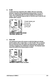
... LED The motherboard comes with a power-on switch. Q LED Q LEDs check key components (CPU, DRAM, VGA card, and booting devices) in soft‑off mode. ASUS Maximus IV GENE-Z 2-21 This user-friendly design provides an intuitional way to indicate that you should shut down the system and unplug the power cable before removing...
... LED The motherboard comes with a power-on switch. Q LED Q LEDs check key components (CPU, DRAM, VGA card, and booting devices) in soft‑off mode. ASUS Maximus IV GENE-Z 2-21 This user-friendly design provides an intuitional way to indicate that you should shut down the system and unplug the power cable before removing...
User Manual
Page 55
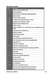
... S3 Resume is stared (S3 Resume PPI is started 3F - 4E OEM post memory initialization codes 4F DXE IPL is called by user (Forced recovery) ASUS Maximus IV GENE-Z 2-23 E7 Reserved for ASL (see ASL Status Codes section below) 31 Memory Installed 32 - 36 CPU post-memory initialization 37 - 3A Post-Memory System...
... S3 Resume is stared (S3 Resume PPI is started 3F - 4E OEM post memory initialization codes 4F DXE IPL is called by user (Forced recovery) ASUS Maximus IV GENE-Z 2-23 E7 Reserved for ASL (see ASL Status Codes section below) 31 Memory Installed 32 - 36 CPU post-memory initialization 37 - 3A Post-Memory System...
User Manual
Page 57
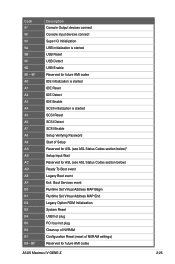
... Initialization System Reset USB hot plug PCI bus hot plug Clean-up of NVRAM Configuration Reset (reset of NVRAM settings) Reserved for future AMI codes ASUS Maximus IV GENE-Z 2-25 Code 97 98 99 9A 9B 9C 9D 9E - 9F A0 A1 A2 A3 A4 A5 A6 A7 A8 A9 AA AB AC AD...
... Initialization System Reset USB hot plug PCI bus hot plug Clean-up of NVRAM Configuration Reset (reset of NVRAM settings) Reserved for future AMI codes ASUS Maximus IV GENE-Z 2-25 Code 97 98 99 9A 9B 9C 9D 9E - 9F A0 A1 A2 A3 A4 A5 A6 A7 A8 A9 AA AB AC AD...
User Manual
Page 59
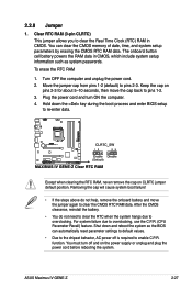
... help, remove the onboard battery and move the cap back to overclocking. For system failure due to pins 2-3. You must turn ON the computer. 4. function. ASUS Maximus IV GENE-Z 2-27 Keep the cap on CLRTC jumper default position.
... help, remove the onboard battery and move the cap back to overclocking. For system failure due to pins 2-3. You must turn ON the computer. 4. function. ASUS Maximus IV GENE-Z 2-27 Keep the cap on CLRTC jumper default position.
User Manual
Page 61
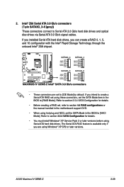
... in the BIOS to create a Serial ATA RAID set the SATA Mode in the motherboard support DVD. • When using Serial ATA hard disk drives. ASUS Maximus IV GENE-Z 2-29 Intel® Z68 Serial ATA 3.0 Gb/s connectors (7-pin SATA3G_3-6 [gray]) These connectors connect to [IDE Mode] by default. The Serial ATA RAID feature is...
... in the BIOS to create a Serial ATA RAID set the SATA Mode in the motherboard support DVD. • When using Serial ATA hard disk drives. ASUS Maximus IV GENE-Z 2-29 Intel® Z68 Serial ATA 3.0 Gb/s connectors (7-pin SATA3G_3-6 [gray]) These connectors connect to [IDE Mode] by default. The Serial ATA RAID feature is...
User Manual
Page 63
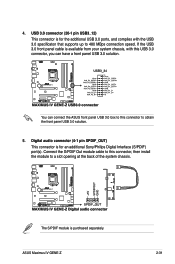
ASUS Maximus IV GENE-Z 2-31 Digital audio connector (4-1 pin SPDIF_OUT) This connector is for an additional Sony/Philips Digital Interface (S/PDIF) port(s). The S/PDIF module is available from your ... connection speed. USB 3.0 connector (20-1 pin USB3_12) This connector is for the additional USB 3.0 ports, and complies with this USB 3.0 connector, you can connect the ASUS front panel USB 3.0 box to this connector, then install the module to obtain the front panel USB 3.0 solution. 5. Connect the S/PDIF Out module cable to...
ASUS Maximus IV GENE-Z 2-31 Digital audio connector (4-1 pin SPDIF_OUT) This connector is for an additional Sony/Philips Digital Interface (S/PDIF) port(s). The S/PDIF module is available from your ... connection speed. USB 3.0 connector (20-1 pin USB3_12) This connector is for the additional USB 3.0 ports, and complies with this USB 3.0 connector, you can connect the ASUS front panel USB 3.0 box to this connector, then install the module to obtain the front panel USB 3.0 solution. 5. Connect the S/PDIF Out module cable to...
User Manual
Page 65
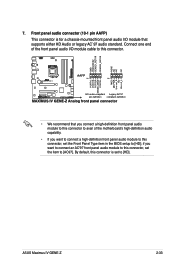
... for a chassis-mounted front panel audio I /O module cable to this connector. • We recommend that supports either HD Audio or legacy AC`97 audio standard. ASUS Maximus IV GENE-Z 2-33 Front panel audio connector (10-1 pin AAFP) This connector is set the Front Panel Type item in the BIOS setup to [AC97].
... for a chassis-mounted front panel audio I /O module cable to this connector. • We recommend that supports either HD Audio or legacy AC`97 audio standard. ASUS Maximus IV GENE-Z 2-33 Front panel audio connector (10-1 pin AAFP) This connector is set the Front Panel Type item in the BIOS setup to [AC97].
User Manual
Page 67
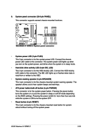
... sleep mode. • Hard disk drive activity LED (2-pin IDE_LED) This 2-pin connector is for the chassis-mounted reset button for the system power LED. 9. ASUS Maximus IV GENE-Z 2-35 Connect the chassis power LED cable to this connector. Connect the HDD Activity LED cable to this connector. System panel connector (20-8 pin PANEL...
... sleep mode. • Hard disk drive activity LED (2-pin IDE_LED) This 2-pin connector is for the chassis-mounted reset button for the system power LED. 9. ASUS Maximus IV GENE-Z 2-35 Connect the chassis power LED cable to this connector. Connect the HDD Activity LED cable to this connector. System panel connector (20-8 pin PANEL...
User Manual
Page 71
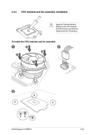
2.3.3 CPU heatsink and fan assembly installation Apply the Thermal Interface Material to the CPU heatsink and CPU before you install the heatsink and fan if necessary. To install the CPU heatsink and fan assembly 1 A 2 B B A 3 ASUS Maximus IV GENE-Z 2-39
2.3.3 CPU heatsink and fan assembly installation Apply the Thermal Interface Material to the CPU heatsink and CPU before you install the heatsink and fan if necessary. To install the CPU heatsink and fan assembly 1 A 2 B B A 3 ASUS Maximus IV GENE-Z 2-39


