User Manual
Page 32
Chapter summary 2 2.1 Before you proceed 2-1 2.2 Motherboard overview 2-2 2.3 Building your computer system 2-36 2.4 Starting up for the first time 2-53 2.5 Turning off the computer 2-54 ASUS Maximus IV GENE-Z
Chapter summary 2 2.1 Before you proceed 2-1 2.2 Motherboard overview 2-2 2.3 Building your computer system 2-36 2.4 Starting up for the first time 2-53 2.5 Turning off the computer 2-54 ASUS Maximus IV GENE-Z
User Manual
Page 33
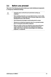
... as the power supply case, to avoid damaging them due to static electricity. • Hold components by the edges to the motherboard, peripherals, or components. ASUS Maximus IV GENE-Z 2-1
... as the power supply case, to avoid damaging them due to static electricity. • Hold components by the edges to the motherboard, peripherals, or components. ASUS Maximus IV GENE-Z 2-1

User Manual
Page 35
... (10-1 pin AAFP) 17. Digital audio connector (4-1 pin SPDIF_OUT) Page 2-19 2-34 2-4 2-32 2-5 2-19 2-31 2-28 2-29 2-35 2-30 2-22 2-18 2-18 2-27 2-33 2-31 ASUS Maximus IV GENE-Z 2-3 ROG Connect switch 2. USB 3.0 connector (USB3_34) 8. Power connectors (24-pin EATXPWR, 8-pin EATX12V) 3. Reset Switch 14. Start Switch 15.
... (10-1 pin AAFP) 17. Digital audio connector (4-1 pin SPDIF_OUT) Page 2-19 2-34 2-4 2-32 2-5 2-19 2-31 2-28 2-29 2-35 2-30 2-22 2-18 2-18 2-27 2-33 2-31 ASUS Maximus IV GENE-Z 2-3 ROG Connect switch 2. USB 3.0 connector (USB3_34) 8. Power connectors (24-pin EATXPWR, 8-pin EATX12V) 3. Reset Switch 14. Start Switch 15.
User Manual
Page 37
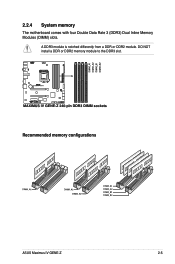
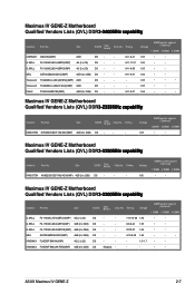
DO NOT install a DDR or DDR2 memory module to the DDR3 slot. Recommended memory configurations ASUS Maximus IV GENE-Z 2-5 2.2.4 System memory The motherboard comes with four Double Data Rate 3 (DDR3) Dual Inline Memory Modules (DIMM) slots. A DDR3 module is notched differently from a DDR or DDR2 module.
DO NOT install a DDR or DDR2 memory module to the DDR3 slot. Recommended memory configurations ASUS Maximus IV GENE-Z 2-5 2.2.4 System memory The motherboard comes with four Double Data Rate 3 (DDR3) Dual Inline Memory Modules (DIMM) slots. A DDR3 module is notched differently from a DDR or DDR2 module.
User Manual
Page 39
... • • DS Kingmax - - - • • ASUS Maximus IV GENE-Z 2-7 Transcend TX2400KLU-4GK (381850)(XMP) 2GB DS - - Voltage 1.65 DIMM socket support (Optional) 1 DIMM 2 DIMM 4 DIMM • • Maximus IV GENE-Z Motherboard Qualified Vendors Lists (QVL) DDR�3�-2�2��0�0&#...2GB) DS - - - Timing KINGSTON KHX2250C9D3T1K2/4GX(XMP) 4GB (2 x 2GB) DS - - - Maximus IV GENE-Z Motherboard Qualified Vendors Lists (QVL) DDR�3�-2�4��0�0��M��H��...
... • • DS Kingmax - - - • • ASUS Maximus IV GENE-Z 2-7 Transcend TX2400KLU-4GK (381850)(XMP) 2GB DS - - Voltage 1.65 DIMM socket support (Optional) 1 DIMM 2 DIMM 4 DIMM • • Maximus IV GENE-Z Motherboard Qualified Vendors Lists (QVL) DDR�3�-2�2��0�0&#...2GB) DS - - - Timing KINGSTON KHX2250C9D3T1K2/4GX(XMP) 4GB (2 x 2GB) DS - - - Maximus IV GENE-Z Motherboard Qualified Vendors Lists (QVL) DDR�3�-2�4��0�0��M��H��...
User Manual
Page 41
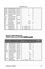
...8226; • • • • • • • • • • • • ASUS Maximus IV GENE-Z 2-9 Team TXD32048M2000C9(XMP) 2GB DS Team T3D1288RT-20 9-9-9-24 1.5 Team TXD32048M2000C9-L(XMP) 2GB DS Team T3D1288LT-20 9-9-9-24 1.5 Team TXD32048M2000C9...; • • • • • • • • • • • Maximus IV GENE-Z Motherboard Qualified Vendors Lists (QVL) DDR�3��-�1��8��6�6��M��H��&#...
...8226; • • • • • • • • • • • • ASUS Maximus IV GENE-Z 2-9 Team TXD32048M2000C9(XMP) 2GB DS Team T3D1288RT-20 9-9-9-24 1.5 Team TXD32048M2000C9-L(XMP) 2GB DS Team T3D1288LT-20 9-9-9-24 1.5 Team TXD32048M2000C9...; • • • • • • • • • • • Maximus IV GENE-Z Motherboard Qualified Vendors Lists (QVL) DDR�3��-�1��8��6�6��M��H��&#...

User Manual
Page 43
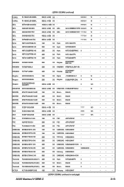
...; • • • • • • • • • • • • • • • • • • • • • • • • • ASUS Maximus IV GENE-Z 2-11 EK Memory EKM324L28BP8-I16(XMP) 4GB (2 x 2GB) DS - - 9 - AEXEA AXA3PS4GK1600S18V(XMP) 4GB (2 x 2GB) DS - - - 1.65 Asint SLZ3128M8-EGJ1D(XMP) 2GB DS Asint 3128M8-GJ1D...
...; • • • • • • • • • • • • • • • • • • • • • • • • • ASUS Maximus IV GENE-Z 2-11 EK Memory EKM324L28BP8-I16(XMP) 4GB (2 x 2GB) DS - - 9 - AEXEA AXA3PS4GK1600S18V(XMP) 4GB (2 x 2GB) DS - - - 1.65 Asint SLZ3128M8-EGJ1D(XMP) 2GB DS Asint 3128M8-GJ1D...
User Manual
Page 45
... TS256MLK64V3N (574206) 2GB SS Micron D9LGK 9 - Transcend TS512MLK64V3N (574831) 4GB DS Micron D9LGK 9 - ACTICA ACT1GHU64B8F1333S 1GB SS Samsung K4B1G0846F - - (DDR3-1333MHz continued on next page) ASUS Maximus IV GENE-Z • • • • • • • • • • • • • • • • • • • • • • • • •...
... TS256MLK64V3N (574206) 2GB SS Micron D9LGK 9 - Transcend TS512MLK64V3N (574831) 4GB DS Micron D9LGK 9 - ACTICA ACT1GHU64B8F1333S 1GB SS Samsung K4B1G0846F - - (DDR3-1333MHz continued on next page) ASUS Maximus IV GENE-Z • • • • • • • • • • • • • • • • • • • • • • • • •...
User Manual
Page 47
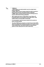
... both the red and gray slots as two pairs of dual-channel memory configuration. • When installing total memory of accessing information from a memory module. ASUS Maximus IV GENE-Z 2-15
... both the red and gray slots as two pairs of dual-channel memory configuration. • When installing total memory of accessing information from a memory module. ASUS Maximus IV GENE-Z 2-15

User Manual
Page 49
...- SATA #1 - - - shared - JMB362 - - - shared - shared - - - shared - - - - - - - - - - - - - - - - shared - - IRQ assignments for this motherboard A B C PCIEx16/8_1 shared - - PCIEx4 - D E F G H - - - - - - - - - - - - - - - - - - - shared - ASM USB3.0#1 - ASUS Maximus IV GENE-Z 2-17 PCIEx16_2 - shared - - - - - - - - ASM USB3.0#0 shared - - shared - - - - shared - - - - shared - - EHCI#1 (USB2.0) - - - High Definition Audio - - - Intel 82579 - - -
...- SATA #1 - - - shared - JMB362 - - - shared - shared - - - shared - - - - - - - - - - - - - - - - shared - - IRQ assignments for this motherboard A B C PCIEx16/8_1 shared - - PCIEx4 - D E F G H - - - - - - - - - - - - - - - - - - - shared - ASM USB3.0#1 - ASUS Maximus IV GENE-Z 2-17 PCIEx16_2 - shared - - - - - - - - ASM USB3.0#0 shared - - shared - - - - shared - - - - shared - - EHCI#1 (USB2.0) - - - High Definition Audio - - - Intel 82579 - - -

User Manual
Page 51
ROG Connect switch Move the slide switch to ON before POST to quickly load the preset profile (GO_Button file) for temporary overclocking when in OS. 4. 3. GO button Press the GO button before you use the ROG Connect function. or press it to enable MemOK! ASUS Maximus IV GENE-Z 2-19
ROG Connect switch Move the slide switch to ON before POST to quickly load the preset profile (GO_Button file) for temporary overclocking when in OS. 4. 3. GO button Press the GO button before you use the ROG Connect function. or press it to enable MemOK! ASUS Maximus IV GENE-Z 2-19
User Manual
Page 53
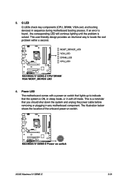
... comes with a power-on switch. This user-friendly design provides an intuitional way to indicate that lights up to locate the root problem within a second. 4. ASUS Maximus IV GENE-Z 2-21 Q LED Q LEDs check key components (CPU, DRAM, VGA card, and booting devices) in soft‑off mode.
... comes with a power-on switch. This user-friendly design provides an intuitional way to indicate that lights up to locate the root problem within a second. 4. ASUS Maximus IV GENE-Z 2-21 Q LED Q LEDs check key components (CPU, DRAM, VGA card, and booting devices) in soft‑off mode.
User Manual
Page 55
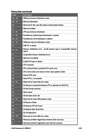
... CPU micro-code is not found or micro-code update is failed 5A Internal CPU error 5B Reset PPI is called by user (Forced recovery) ASUS Maximus IV GENE-Z 2-23 EF Reserved for future AMI error codes E0 S3 Resume is stared (S3 Resume PPI is not available 5C - 5F Reserved for future AMI...
... CPU micro-code is not found or micro-code update is failed 5A Internal CPU error 5B Reset PPI is called by user (Forced recovery) ASUS Maximus IV GENE-Z 2-23 EF Reserved for future AMI error codes E0 S3 Resume is stared (S3 Resume PPI is not available 5C - 5F Reserved for future AMI...
User Manual
Page 57
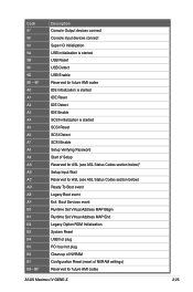
... Initialization System Reset USB hot plug PCI bus hot plug Clean-up of NVRAM Configuration Reset (reset of NVRAM settings) Reserved for future AMI codes ASUS Maximus IV GENE-Z 2-25 Code 97 98 99 9A 9B 9C 9D 9E - 9F A0 A1 A2 A3 A4 A5 A6 A7 A8 A9 AA AB AC AD...
... Initialization System Reset USB hot plug PCI bus hot plug Clean-up of NVRAM Configuration Reset (reset of NVRAM settings) Reserved for future AMI codes ASUS Maximus IV GENE-Z 2-25 Code 97 98 99 9A 9B 9C 9D 9E - 9F A0 A1 A2 A3 A4 A5 A6 A7 A8 A9 AA AB AC AD...
User Manual
Page 59
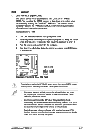
... power cord before rebooting the system. function. You can automatically reset parameter settings to default values. • Due to clear the CMOS RTC RAM data. ASUS Maximus IV GENE-Z 2-27 For system failure due to pins 2-3. Shut down the key during the boot process and enter BIOS setup to overclocking. Keep the cap on...
... power cord before rebooting the system. function. You can automatically reset parameter settings to default values. • Due to clear the CMOS RTC RAM data. ASUS Maximus IV GENE-Z 2-27 For system failure due to pins 2-3. Shut down the key during the boot process and enter BIOS setup to overclocking. Keep the cap on...
User Manual
Page 61
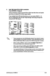
... are set to section 4.4 RAID configurations or the manual bundled in the motherboard support DVD. • When using Windows® XP SP2 or later versions. ASUS Maximus IV GENE-Z 2-29 If you can create a RAID 0, 1, 5, and 10 configuration with the Intel® Rapid Storage Technology through the onboard Intel® Z68 chipset. • These...
... are set to section 4.4 RAID configurations or the manual bundled in the motherboard support DVD. • When using Windows® XP SP2 or later versions. ASUS Maximus IV GENE-Z 2-29 If you can create a RAID 0, 1, 5, and 10 configuration with the Intel® Rapid Storage Technology through the onboard Intel® Z68 chipset. • These...
User Manual
Page 63
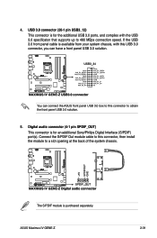
... can have a front panel USB 3.0 solution. Connect the S/PDIF Out module cable to this USB 3.0 connector, you can connect the ASUS front panel USB 3.0 box to this connector to a slot opening at the back of the system chassis. Digital audio connector (4-1 pin ...USB 3.0 specificaton that supports up to 480 MBps connection speed. The S/PDIF module is for an additional Sony/Philips Digital Interface (S/PDIF) port(s). 4. ASUS Maximus IV GENE-Z 2-31 If the USB 3.0 front panel cable is for the additional USB 3.0 ports, and complies with this connector, then install the module to...
... can have a front panel USB 3.0 solution. Connect the S/PDIF Out module cable to this USB 3.0 connector, you can connect the ASUS front panel USB 3.0 box to this connector to a slot opening at the back of the system chassis. Digital audio connector (4-1 pin ...USB 3.0 specificaton that supports up to 480 MBps connection speed. The S/PDIF module is for an additional Sony/Philips Digital Interface (S/PDIF) port(s). 4. ASUS Maximus IV GENE-Z 2-31 If the USB 3.0 front panel cable is for the additional USB 3.0 ports, and complies with this connector, then install the module to...
User Manual
Page 65
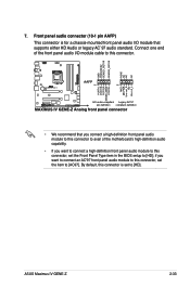
...`97 audio standard. Front panel audio connector (10-1 pin AAFP) This connector is set the Front Panel Type item in the BIOS setup to [HD]; ASUS Maximus IV GENE-Z 2-33 if you want to connect an AC'97 front panel audio module to this connector, set to [AC97]. Connect one end of the front...
...`97 audio standard. Front panel audio connector (10-1 pin AAFP) This connector is set the Front Panel Type item in the BIOS setup to [HD]; ASUS Maximus IV GENE-Z 2-33 if you want to connect an AC'97 front panel audio module to this connector, set to [AC97]. Connect one end of the front...
User Manual
Page 67
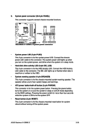
... the system power, and blinks when the system is in sleep or soft-off button (2-pin PWRSW) This connector is for the HDD Activity LED. ASUS Maximus IV GENE-Z 2-35 Connect the HDD Activity LED cable to this connector. The IDE LED lights up when you to the HDD. • System warning speaker (4-pin...
... the system power, and blinks when the system is in sleep or soft-off button (2-pin PWRSW) This connector is for the HDD Activity LED. ASUS Maximus IV GENE-Z 2-35 Connect the HDD Activity LED cable to this connector. The IDE LED lights up when you to the HDD. • System warning speaker (4-pin...
User Manual
Page 71
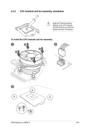
To install the CPU heatsink and fan assembly 1 A 2 B B A 3 ASUS Maximus IV GENE-Z 2-39 2.3.3 CPU heatsink and fan assembly installation Apply the Thermal Interface Material to the CPU heatsink and CPU before you install the heatsink and fan if necessary.
To install the CPU heatsink and fan assembly 1 A 2 B B A 3 ASUS Maximus IV GENE-Z 2-39 2.3.3 CPU heatsink and fan assembly installation Apply the Thermal Interface Material to the CPU heatsink and CPU before you install the heatsink and fan if necessary.


