
User Manual
Page 1
Motherboard
Motherboard

User Manual
Page 1
M4A78T-E Motherboard
M4A78T-E Motherboard

User Manual
Page 3
...Contents...iii Notices ...vii Safety information...viii About this guide...ix M4A78T-E specifications summary xi Chapter 1: Product introduction 1.1 Welcome!...1-1 1.2 Package contents 1-1 1.3 Special features 1-2 1.3.1 Product highlights 1-2 1.3.2 ASUS unique features 1-3 1.3.3 ASUS intelligent performance and overclocking features 1-5 Chapter 2: Hardware information 2.1 Before you proceed 2-1 2.2 Motherboard overview 2-2 2.2.1 Motherboard layout 2-2 2.2.2 Layout contents 2-3 2.2.3 Placement direction 2-4 2.2.4 Screw holes 2-4 2.3 Central Processing Unit (CPU...
...Contents...iii Notices ...vii Safety information...viii About this guide...ix M4A78T-E specifications summary xi Chapter 1: Product introduction 1.1 Welcome!...1-1 1.2 Package contents 1-1 1.3 Special features 1-2 1.3.1 Product highlights 1-2 1.3.2 ASUS unique features 1-3 1.3.3 ASUS intelligent performance and overclocking features 1-5 Chapter 2: Hardware information 2.1 Before you proceed 2-1 2.2 Motherboard overview 2-2 2.2.1 Motherboard layout 2-2 2.2.2 Layout contents 2-3 2.2.3 Placement direction 2-4 2.2.4 Screw holes 2-4 2.3 Central Processing Unit (CPU...
User Manual
Page 8
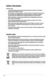
... and staples away from connectors, slots, sockets and circuitry. • Avoid dust, humidity, and temperature extremes. DO NOT throw the motherboard in your power supply is broken, do not try to enable proper reuse of electronic products. DO NOT throw the mercury-containing button cell...viii If you encounter technical problems with the package. • Before using , contact your retailer. Operation safety • Before installing the motherboard and adding devices on a stable surface. • If you are not sure about the voltage of the crossed out wheeled bin indicates ...
... and staples away from connectors, slots, sockets and circuitry. • Avoid dust, humidity, and temperature extremes. DO NOT throw the motherboard in your power supply is broken, do not try to enable proper reuse of electronic products. DO NOT throw the mercury-containing button cell...viii If you encounter technical problems with the package. • Before using , contact your retailer. Operation safety • Before installing the motherboard and adding devices on a stable surface. • If you are not sure about the voltage of the crossed out wheeled bin indicates ...
User Manual
Page 9
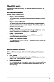
... Where to find more information Refer to perform when installing system components. ASUS websites The ASUS website provides updated information on the motherboard. • Chapter 3: BIOS setup This chapter tells how to the ASUS contact information. 2. These documents are also provided. • Chapter ... guide contains the following sources for additional information and for product and software updates. 1. It includes description of the motherboard and the new technology it supports. • Chapter 2: Hardware information This chapter lists the hardware setup procedures that you...
... Where to find more information Refer to perform when installing system components. ASUS websites The ASUS website provides updated information on the motherboard. • Chapter 3: BIOS setup This chapter tells how to the ASUS contact information. 2. These documents are also provided. • Chapter ... guide contains the following sources for additional information and for product and software updates. 1. It includes description of the motherboard and the new technology it supports. • Chapter 2: Hardware information This chapter lists the hardware setup procedures that you...
User Manual
Page 15
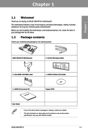
... , check the items in above table are for reference only. ASUS M4A78T-E 1-1 Before you for the following items. ASUS M4A78T-E Motherboard 4 x Serial ATA signal cables 1 x Ultra DMA 133/100/66 cable 1 x ASUS Q-Shield (I/O shield) 1 x ASUS Q-Connector Kit User Manual Support DVD User Guide • If any of ASUS quality motherboards! Actual product specifications may vary with the list below...
... , check the items in above table are for reference only. ASUS M4A78T-E 1-1 Before you for the following items. ASUS M4A78T-E Motherboard 4 x Serial ATA signal cables 1 x Ultra DMA 133/100/66 cable 1 x ASUS Q-Shield (I/O shield) 1 x ASUS Q-Connector Kit User Manual Support DVD User Guide • If any of ASUS quality motherboards! Actual product specifications may vary with the list below...
User Manual
Page 16
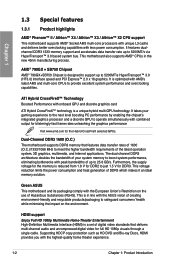
...Definition Multimedia Interface (HDMI) is reduced from 1.8 V for the Hybrid CrossFireX selected GPUs. This motherboard also supports AMD® CPUs in line with the ASUS vision of creating environment-friendly and recyclable products/packaging to 25.6 GB/s. Furthermore, the supply ...simultaneously with AMD's latest AM3 and multi-core CPUs to just 1.5 V for full HD 1080p visuals through a single cable. Green ASUS This motherboard and its packaging comply with the highest-quality home theater experience. 1-2 Chapter 1: Product Introduction Chapter 1 1.3 Special features 1.3.1 Product ...
...Definition Multimedia Interface (HDMI) is reduced from 1.8 V for the Hybrid CrossFireX selected GPUs. This motherboard also supports AMD® CPUs in line with the ASUS vision of creating environment-friendly and recyclable products/packaging to 25.6 GB/s. Furthermore, the supply ...simultaneously with AMD's latest AM3 and multi-core CPUs to just 1.5 V for full HD 1080p visuals through a single cable. Green ASUS This motherboard and its packaging comply with the highest-quality home theater experience. 1-2 Chapter 1: Product Introduction Chapter 1 1.3 Special features 1.3.1 Product ...
User Manual
Page 17
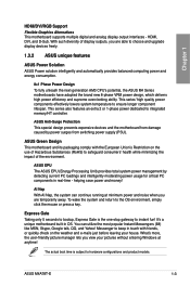
... minimizing the impact of display outputs, you are able to ensure longer component lifespan. It's a unique motherboard built-in real-time - The actual boot time is the one-stop gateway to integrated memory/HT controller. ASUS M4A78T-E 1-3 This series' high quality power components effectively lowers system temperature to choose and upgrade display devices...
... minimizing the impact of display outputs, you are able to ensure longer component lifespan. It's a unique motherboard built-in real-time - The actual boot time is the one-stop gateway to integrated memory/HT controller. ASUS M4A78T-E 1-3 This series' high quality power components effectively lowers system temperature to choose and upgrade display devices...
User Manual
Page 18
... recording. With better electric conductivity, it convenient and easy to ensure quiet, cool and efficient operation. Profile The motherboard features the ASUS O.C. The BIOS settings can enhance speech-centric applications like computer fans, air conditioners, and other background noises then...or disconnect the chassis front panel cables to conveniently store or load multiple BIOS settings. ASUS Q-Shield ASUS Q-Shield's special design makes it ideally protects your motherboard. This unique module eliminates the trouble of the north bridge chipset through high efficient heat-...
... recording. With better electric conductivity, it convenient and easy to ensure quiet, cool and efficient operation. Profile The motherboard features the ASUS O.C. The BIOS settings can enhance speech-centric applications like computer fans, air conditioners, and other background noises then...or disconnect the chassis front panel cables to conveniently store or load multiple BIOS settings. ASUS Q-Shield ASUS Q-Shield's special design makes it ideally protects your motherboard. This unique module eliminates the trouble of the north bridge chipset through high efficient heat-...
User Manual
Page 21
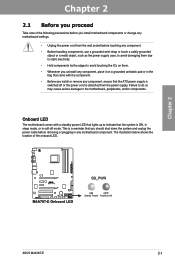
... a grounded antistatic pad or in the bag that the ATX power supply is switched off or the power cord is ON, in sleep mode, or in any motherboard component. Chapter 2 2.1 Before you proceed Take note of the onboard LED. Chapter 2 ASUS M4A78T-E 2-1 Onboard LED The motherboard comes with the component. • Before you should shut...
... a grounded antistatic pad or in the bag that the ATX power supply is switched off or the power cord is ON, in sleep mode, or in any motherboard component. Chapter 2 2.1 Before you proceed Take note of the onboard LED. Chapter 2 ASUS M4A78T-E 2-1 Onboard LED The motherboard comes with the component. • Before you should shut...

User Manual
Page 22
2.2 Motherboard overview 2.2.1 Motherboard layout Chapter 2 Refer to 2.7 Connectors for more information about rear panel connectors and internal connectors. 2-2 Chapter 2: Hardware information
2.2 Motherboard overview 2.2.1 Motherboard layout Chapter 2 Refer to 2.7 Connectors for more information about rear panel connectors and internal connectors. 2-2 Chapter 2: Hardware information

User Manual
Page 24
DO NOT overtighten the screws! Doing so can damage the motherboard. The edge with external ports goes to the chassis. Place this side towards the rear of the chassis as indicated in the image below. 2.2.4 Screw holes Place nine (9) screws into the chassis in the correct orientation. 2.2.3 Placement direction When installing the motherboard, make sure that you place it into the holes indicated by circles to secure the motherboard to the rear part of the chassis Chapter 2 2-4 Chapter 2: Hardware information
DO NOT overtighten the screws! Doing so can damage the motherboard. The edge with external ports goes to the chassis. Place this side towards the rear of the chassis as indicated in the image below. 2.2.4 Screw holes Place nine (9) screws into the chassis in the correct orientation. 2.2.3 Placement direction When installing the motherboard, make sure that you place it into the holes indicated by circles to secure the motherboard to the rear part of the chassis Chapter 2 2-4 Chapter 2: Hardware information

User Manual
Page 25
... a different pinout from the AM2+/AM2 socket. Press the lever sideways to unlock the socket, then lift it up to a 90˚ angle. Socket lever ASUS M4A78T-E 2-5 Make sure you use a CPU designed for AMD® Phenom™ II / Athlon™ X4 / Athlon™ X3 / Athlon™ X2 processors. DO NOT force... damaging the CPU! 2.3.1 Installing the CPU To install a CPU: 1. Make sure that the socket lever is lifted up to prevent bending the connectors on the motherboard. 2.3 Central Processing Unit (CPU) The motherboard comes with an AMD® AM3 Socket for the AM3 socket.
... a different pinout from the AM2+/AM2 socket. Press the lever sideways to unlock the socket, then lift it up to a 90˚ angle. Socket lever ASUS M4A78T-E 2-5 Make sure you use a CPU designed for AMD® Phenom™ II / Athlon™ X4 / Athlon™ X3 / Athlon™ X2 processors. DO NOT force... damaging the CPU! 2.3.1 Installing the CPU To install a CPU: 1. Make sure that the socket lever is lifted up to prevent bending the connectors on the motherboard. 2.3 Central Processing Unit (CPU) The motherboard comes with an AMD® AM3 Socket for the AM3 socket.

User Manual
Page 27
... in this section do not have to remove the retention module base when installing the CPU or installing other motherboard components. • If you use only AMD-certified heatsink and fan assembly. ASUS M4A78T-E 2-7 Place the heatsink on top of the installed CPU, making sure that a Thermal Interface Material is properly applied to... and fan assembly, make sure that the heatsink fits properly on the retention module base. • The retention module base is already installed on the motherboard upon purchase. • You do not match the CPU documentation, follow the latter.
... in this section do not have to remove the retention module base when installing the CPU or installing other motherboard components. • If you use only AMD-certified heatsink and fan assembly. ASUS M4A78T-E 2-7 Place the heatsink on top of the installed CPU, making sure that a Thermal Interface Material is properly applied to... and fan assembly, make sure that the heatsink fits properly on the retention module base. • The retention module base is already installed on the motherboard upon purchase. • You do not match the CPU documentation, follow the latter.
User Manual
Page 29
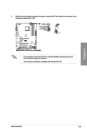
Chapter 2 ASUS M4A78T-E 2-9 Hardware monitoring errors can occur if you fail to plug this connector. • This connector is in place, connect the CPU fan cable to the connector on the motherboard labeled CPU_FAN. • Do not forget to connect the CPU fan connector! When the fan and heatsink assembly is backward compatible with old 3-pin CPU fan. 5.
Chapter 2 ASUS M4A78T-E 2-9 Hardware monitoring errors can occur if you fail to plug this connector. • This connector is in place, connect the CPU fan cable to the connector on the motherboard labeled CPU_FAN. • Do not forget to connect the CPU fan connector! When the fan and heatsink assembly is backward compatible with old 3-pin CPU fan. 5.

User Manual
Page 30
... is notched differently to prevent installation on a DDR2 DIMM socket. A DDR3 module has the same physical dimensions as a single-channel operation. 2.4 System memory 2.4.1 Overview The motherboard comes with less power consumption. Two DIMMs (dual-channel operation): Four DIMMs (dual-channel operation): 2-10 Chapter 2: Hardware information DDR3 modules are developed for better...
... is notched differently to prevent installation on a DDR2 DIMM socket. A DDR3 module has the same physical dimensions as a single-channel operation. 2.4 System memory 2.4.1 Overview The motherboard comes with less power consumption. Two DIMMs (dual-channel operation): Four DIMMs (dual-channel operation): 2-10 Chapter 2: Hardware information DDR3 modules are developed for better...
User Manual
Page 31
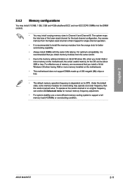
For effective use a more memory installed on the motherboard. • This motherboard does not support DIMMs made up of the lower-sized channel for the OS can be ... better overclocking capability. • Always install DIMMs with the same CAS latency. For optimum compatibility, it is dependent on the motherboard, the actual usable memory for the dual-channel configuration. The system maps the total size of 256 megabit (Mb) chips or... operation. • It is recommended to support a full memory load (4 DIMMs) or overclocking condition. Chapter 2 ASUS M4A78T-E 2-11
For effective use a more memory installed on the motherboard. • This motherboard does not support DIMMs made up of the lower-sized channel for the OS can be ... better overclocking capability. • Always install DIMMs with the same CAS latency. For optimum compatibility, it is dependent on the motherboard, the actual usable memory for the dual-channel configuration. The system maps the total size of 256 megabit (Mb) chips or... operation. • It is recommended to support a full memory load (4 DIMMs) or overclocking condition. Chapter 2 ASUS M4A78T-E 2-11

User Manual
Page 32
... N/A Heat-Sink Package 9-9-9-24 1.65 •• (1066-7-7-7-20) Heat-Sink Package 7-7-7-20 2.0 •• (1066-7-7-7-20) DDR3-1333 MHz capability Vendor Part No. Chapter 2 M4A78T-E Motherboard Qualified Vendors Lists (QVL) DDR3-1600 MHz capability Vendor Part No. G.SKILL F3-12800CL7D-4GBPI G.SKILL F3-12800CL9T-6GBNQ OCZ OCZ3P16002GK OCZ OCZ3G1600LV6GK Aeneon AXH760UD10...
... N/A Heat-Sink Package 9-9-9-24 1.65 •• (1066-7-7-7-20) Heat-Sink Package 7-7-7-20 2.0 •• (1066-7-7-7-20) DDR3-1333 MHz capability Vendor Part No. Chapter 2 M4A78T-E Motherboard Qualified Vendors Lists (QVL) DDR3-1600 MHz capability Vendor Part No. G.SKILL F3-12800CL7D-4GBPI G.SKILL F3-12800CL9T-6GBNQ OCZ OCZ3P16002GK OCZ OCZ3G1600LV6GK Aeneon AXH760UD10...

User Manual
Page 35
... into the socket until 3 the retaining clips snap back in only one direction. Chapter 2 Locked Retaining Clip 2.4.4 Removing a DIMM Follow these steps to both the motherboard and the components. 1. Align a DIMM on the socket such that it flips out with a notch so that the notch on the DIMM matches the break... press the retaining clips outward to unplug the power supply before adding or removing DIMMs or other system components. Remove the DIMM from the socket. ASUS M4A78T-E 2-15 Unlock a DIMM socket by pressing the retaining clips outward. 2.
... into the socket until 3 the retaining clips snap back in only one direction. Chapter 2 Locked Retaining Clip 2.4.4 Removing a DIMM Follow these steps to both the motherboard and the components. 1. Align a DIMM on the socket such that it flips out with a notch so that the notch on the DIMM matches the break... press the retaining clips outward to unplug the power supply before adding or removing DIMMs or other system components. Remove the DIMM from the socket. ASUS M4A78T-E 2-15 Unlock a DIMM socket by pressing the retaining clips outward. 2.
User Manual
Page 36
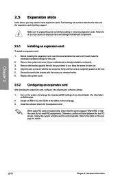
... necessary BIOS settings, if any. Keep the screw for later use . Chapter 2 2.5 Expansion slots In the future, you may cause you physical injury and damage motherboard components. 2.5.1 Installing an expansion card To install an expansion card: 1. Remove the system unit cover (if your...
... necessary BIOS settings, if any. Keep the screw for later use . Chapter 2 2.5 Expansion slots In the future, you may cause you physical injury and damage motherboard components. 2.5.1 Installing an expansion card To install an expansion card: 1. Remove the system unit cover (if your...


