User Manual
Page 10
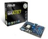
M4A78LT Series specifications summary Back panel I/O ports Internal I/O connectors BIOS Accessories Support DVD Form factor 1 x LPT port 1 x PS/2 Keyboard port 1 x PS/2 Mouse port 1 x LAN (RJ-45) ... connectors 1 x Front panel audio connector 1 x CPU fan connector 1 x Chassis fan connector 1 x IDE connector 1 x System panel connector 1 x S/PDIF Out connector 1 x 24-pin EATX power connector 1 x 4-pin ATX 12V power connector 8 Mb Flash ROM, AMI BIOS, PnP, DMI v2.0, WfM 2.0, ACPI v2.0a, SM BIOS v2.5 2 x Serial ATA cables 1 x I/O shield 1 x User Manual Drivers...
M4A78LT Series specifications summary Back panel I/O ports Internal I/O connectors BIOS Accessories Support DVD Form factor 1 x LPT port 1 x PS/2 Keyboard port 1 x PS/2 Mouse port 1 x LAN (RJ-45) ... connectors 1 x Front panel audio connector 1 x CPU fan connector 1 x Chassis fan connector 1 x IDE connector 1 x System panel connector 1 x S/PDIF Out connector 1 x 24-pin EATX power connector 1 x 4-pin ATX 12V power connector 8 Mb Flash ROM, AMI BIOS, PnP, DMI v2.0, WfM 2.0, ACPI v2.0a, SM BIOS v2.5 2 x Serial ATA cables 1 x I/O shield 1 x User Manual Drivers...

User Manual
Page 15
.... This is a reminder that the system is ON, in sleep mode, or in any component, switch off mode. M4A78LT Series SB_PWR ON OFF Standby Power Powered Off M4A78LT Series Onboard LED ASUS M4A78LT Series 1-5 Failure to do so may cause severe damage to indicate that you install or remove any motherboard component. The... motherboard components or change any motherboard settings. • Unplug the power cord from the wall socket before removing or plugging in soft-off the ATX power supply and detach its power cord. 1.4 Before you proceed Take note of the onboard LED.
.... This is a reminder that the system is ON, in sleep mode, or in any component, switch off mode. M4A78LT Series SB_PWR ON OFF Standby Power Powered Off M4A78LT Series Onboard LED ASUS M4A78LT Series 1-5 Failure to do so may cause severe damage to indicate that you install or remove any motherboard component. The... motherboard components or change any motherboard settings. • Unplug the power cord from the wall socket before removing or plugging in soft-off the ATX power supply and detach its power cord. 1.4 Before you proceed Take note of the onboard LED.

User Manual
Page 18
... (40-1 pin PRI_IDE) 1-24 USBPW5-10) 2. The AM3 socket has a different pinout from the AM2+/AM2 socket. M4A78LT Series M4A78LT Series CPU socket AM3 1-8 Chapter 1: Product introduction 1.5.4 Layout contents Connectors/Jumpers/Slots Page Connectors/Jumpers/Slots Page 1. USB ...device wake-up (3-pin USBPW1-4, 1-20 8. CPU and chassis fan connectors (4-pin CPU_FAN, 3-pin CHA_FAN) 1-28 11. ATX power connectors...
... (40-1 pin PRI_IDE) 1-24 USBPW5-10) 2. The AM3 socket has a different pinout from the AM2+/AM2 socket. M4A78LT Series M4A78LT Series CPU socket AM3 1-8 Chapter 1: Product introduction 1.5.4 Layout contents Connectors/Jumpers/Slots Page Connectors/Jumpers/Slots Page 1. USB ...device wake-up (3-pin USBPW1-4, 1-20 8. CPU and chassis fan connectors (4-pin CPU_FAN, 3-pin CHA_FAN) 1-28 11. ATX power connectors...

User Manual
Page 30
... (Default) M4A78LT Series USB Device Wake Up 3. Keyboard power (3-pin KBPWR) This jumper allows you to pins 2-3 (+5VSB), you set this jumper to enable or disable the keyboard wake-up the computer by pressing a key on the +5VSB lead, and a corresponding setting in reduced power mode). This feature requires an ATX power... in low power mode) using the connected USB devices. When you can supply at least 1A on the keyboard. 2. KBPWR 12 23 +5V +5VSB (Default) M4A78LT Series M4A78LT Series Keyboard Power Setting 1-20 Chapter 1: Product introduction
... (Default) M4A78LT Series USB Device Wake Up 3. Keyboard power (3-pin KBPWR) This jumper allows you to pins 2-3 (+5VSB), you set this jumper to enable or disable the keyboard wake-up the computer by pressing a key on the +5VSB lead, and a corresponding setting in reduced power mode). This feature requires an ATX power... in low power mode) using the connected USB devices. When you can supply at least 1A on the keyboard. 2. KBPWR 12 23 +5V +5VSB (Default) M4A78LT Series M4A78LT Series Keyboard Power Setting 1-20 Chapter 1: Product introduction

User Manual
Page 33
...and push down firmly until the connectors completely fit. The plugs from the power supply are designed to install additional devices. ASUS M4A78LT Series 1-23 2. ATX12V EATXPWR +12V DC +12V DC M4A78LT Series GND GND +3 Volts +12 Volts +12 Volts +5V Standby Power OK PIN 1 GND +5 Volts GND +5 Volts... become unstable or may not boot up . • We recommend that the PSU has a minimum power rating of 300W power rating. ATX power connectors (24-pin EATXPWR, 4-pin ATX12V) These connectors are uncertain about the minimum power supply requirement for your system, refer to ...
...and push down firmly until the connectors completely fit. The plugs from the power supply are designed to install additional devices. ASUS M4A78LT Series 1-23 2. ATX12V EATXPWR +12V DC +12V DC M4A78LT Series GND GND +3 Volts +12 Volts +12 Volts +5V Standby Power OK PIN 1 GND +5 Volts GND +5 Volts... become unstable or may not boot up . • We recommend that the PSU has a minimum power rating of 300W power rating. ATX power connectors (24-pin EATXPWR, 4-pin ATX12V) These connectors are uncertain about the minimum power supply requirement for your system, refer to ...

User Manual
Page 36
...-mounted system warning speaker. Connect the HDD Activity LED cable to this connector. PWR Ground Reset Ground IDE_LED PWRSW RESET * Requires an ATX power supply M4A78LT Series System panel connector • System power LED (2-pin PLED) This 2-pin connector is for the HDD Activity LED. 5. Connect ...the chassis power LED cable to this connector. PLED SPEAKER PLED+ PLED+5V Ground Ground Speaker M4A78LT Series PANEL PIN 1 IDE_LED+ IDE_LED- The system power LED lights up or flashes when data is read from or written to hear system...
...-mounted system warning speaker. Connect the HDD Activity LED cable to this connector. PWR Ground Reset Ground IDE_LED PWRSW RESET * Requires an ATX power supply M4A78LT Series System panel connector • System power LED (2-pin PLED) This 2-pin connector is for the HDD Activity LED. 5. Connect ...the chassis power LED cable to this connector. PLED SPEAKER PLED+ PLED+5V Ground Ground Speaker M4A78LT Series PANEL PIN 1 IDE_LED+ IDE_LED- The system power LED lights up or flashes when data is read from or written to hear system...

User Manual
Page 58
This feature requires an ATX power supply that smartly adjusts the CPU fan speeds for more efficient system operation. Select [gnored] if you to individually set the appropriate performance level ... onboard hardware monitor automatically detects and displays the CPU / Chassis fan speeds in rotations per minute (RPM). CPU Q-Fan Function [Enabled] Enables or disables the ASUS Q-Fan feature that provides at least 1A on the system. Configuration options: [Disabled] [Space Bar] [Power Key] [Ctrl-Esc] Power On By PS/2 Mouse [Disabled...
This feature requires an ATX power supply that smartly adjusts the CPU fan speeds for more efficient system operation. Select [gnored] if you to individually set the appropriate performance level ... onboard hardware monitor automatically detects and displays the CPU / Chassis fan speeds in rotations per minute (RPM). CPU Q-Fan Function [Enabled] Enables or disables the ASUS Q-Fan feature that provides at least 1A on the system. Configuration options: [Disabled] [Space Bar] [Power Key] [Ctrl-Esc] Power On By PS/2 Mouse [Disabled...


