
User Manual
Page 11
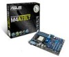
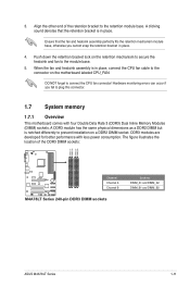
...5200MT/s via HyperTransport™ 3.0based system bus. ASUS M4A78LT Series 1-1 Before you for the following items. Motherboard Cables Accessories Application DVD Documentation ASUS M4A78LT Series motherboard 2 x Serial ATA cables 1 x I/O shield ASUS motherboard Support DVD User Manual • M4A78LT Series motherboards include M4A78LT and M4A78LT LE two models. This motherboard also supports AMD®... motherboard delivers a host of new features and latest technologies, making it , check the items in your motherboard package for buying an ASUS® M4A78LT Series motherboard!
...5200MT/s via HyperTransport™ 3.0based system bus. ASUS M4A78LT Series 1-1 Before you for the following items. Motherboard Cables Accessories Application DVD Documentation ASUS M4A78LT Series motherboard 2 x Serial ATA cables 1 x I/O shield ASUS motherboard Support DVD User Manual • M4A78LT Series motherboards include M4A78LT and M4A78LT LE two models. This motherboard also supports AMD®... motherboard delivers a host of new features and latest technologies, making it , check the items in your motherboard package for buying an ASUS® M4A78LT Series motherboard!
User Manual
Page 13
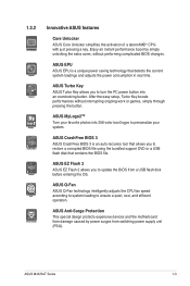
... tool that allows you to personalize your favorite photos into an overclocking button. ASUS CrashFree BIOS 3 ASUS CrashFree BIOS 3 is a unique power saving technology that contains the BIOS file. ASUS M4A78LT Series 1-3 ASUS MyLogo2™ Turn your system. 1.3.2 Innovative ASUS features Core Unlocker ASUS Core Unlocker simplifies the activation of a latent AMD® CPUwith just pressing a key...
... tool that allows you to personalize your favorite photos into an overclocking button. ASUS CrashFree BIOS 3 ASUS CrashFree BIOS 3 is a unique power saving technology that contains the BIOS file. ASUS M4A78LT Series 1-3 ASUS MyLogo2™ Turn your system. 1.3.2 Innovative ASUS features Core Unlocker ASUS Core Unlocker simplifies the activation of a latent AMD® CPUwith just pressing a key...

User Manual
Page 15
... from the wall socket before removing or plugging in soft-off the ATX power supply and detach its power cord. M4A78LT Series SB_PWR ON OFF Standby Power Powered Off M4A78LT Series Onboard LED ASUS M4A78LT Series 1-5 The illustration below shows the location of the following precautions before you install or remove any component, switch...
... from the wall socket before removing or plugging in soft-off the ATX power supply and detach its power cord. M4A78LT Series SB_PWR ON OFF Standby Power Powered Off M4A78LT Series Onboard LED ASUS M4A78LT Series 1-5 The illustration below shows the location of the following precautions before you install or remove any component, switch...
User Manual
Page 17
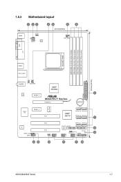
... module) DDR3 DIMM_B2 (64bit, 240-pin module) SOCKET AM3 USB34 LAN1_USB12 30.5cm(12.0in) USBPW1-4 AUDIO CHA_FAN AMD® RS780L EATXPWR 2 RTL 8111E PCIEX1_1 M4A78LT Series PCIEX16_1 Lithium Cell CMOS Power ICS 9LPRS483 Super I/O PCIEX1_2 PCI1 SATA3G_5 SATA3G_6 AMD® SB710 SATA3G_3 SATA3G_4 7 ALC 887 SPDIF_OUT AAFP PCI2 SATA3G_1 SATA3G_2...
... module) DDR3 DIMM_B2 (64bit, 240-pin module) SOCKET AM3 USB34 LAN1_USB12 30.5cm(12.0in) USBPW1-4 AUDIO CHA_FAN AMD® RS780L EATXPWR 2 RTL 8111E PCIEX1_1 M4A78LT Series PCIEX16_1 Lithium Cell CMOS Power ICS 9LPRS483 Super I/O PCIEX1_2 PCI1 SATA3G_5 SATA3G_6 AMD® SB710 SATA3G_3 SATA3G_4 7 ALC 887 SPDIF_OUT AAFP PCI2 SATA3G_1 SATA3G_2...
User Manual
Page 19
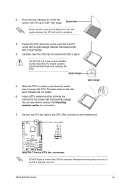
... 1.6.2 Installing heatsink and fan for instructions. The lever clicks on the motherboard. Press the lever sideways to unlock the socket, then lift it is locked. 6. ASUS M4A78LT Series 1-9 Carefully insert the CPU into the socket to connect the CPU fan connector! Gold triangle 7. Small triangle 5. CPU_FAN GND CPU FAN PWR CPU FAN...
... 1.6.2 Installing heatsink and fan for instructions. The lever clicks on the motherboard. Press the lever sideways to unlock the socket, then lift it is locked. 6. ASUS M4A78LT Series 1-9 Carefully insert the CPU into the socket to connect the CPU fan connector! Gold triangle 7. Small triangle 5. CPU_FAN GND CPU FAN PWR CPU FAN...
User Manual
Page 21
... is in place. 4. Align the other end of the DDR3 DIMM sockets: DIMM_A1 DIMM_A2 DIMM_B1 DIMM_B2 M4A78LT Series Channel Channel A Channel B M4A78LT Series 240-pin DDR3 DIMM sockets Sockets DIMM_A1 and DIMM_A2 DIMM_B1 and DIMM_B2 ASUS M4A78LT Series 1-11 A clicking sound denotes that the fan and heatsink assembly perfectly fits the retention mechanism module...
... is in place. 4. Align the other end of the DDR3 DIMM sockets: DIMM_A1 DIMM_A2 DIMM_B1 DIMM_B2 M4A78LT Series Channel Channel A Channel B M4A78LT Series 240-pin DDR3 DIMM sockets Sockets DIMM_A1 and DIMM_A2 DIMM_B1 and DIMM_B2 ASUS M4A78LT Series 1-11 A clicking sound denotes that the fan and heatsink assembly perfectly fits the retention mechanism module...

User Manual
Page 27
... fits in place 3 and the DIMM is keyed with a notch so that it flips out with your fingers when pressing the retaining 1 clips. DIMM notch ASUS M4A78LT Series 1-17 1.7.3 Installing a DIMM Unplug the power supply before adding or removing DIMMs or other system components. Remove the DIMM from the socket. Align a DIMM...
... fits in place 3 and the DIMM is keyed with a notch so that it flips out with your fingers when pressing the retaining 1 clips. DIMM notch ASUS M4A78LT Series 1-17 1.7.3 Installing a DIMM Unplug the power supply before adding or removing DIMMs or other system components. Remove the DIMM from the socket. Align a DIMM...

User Manual
Page 29
The onboard button cell battery powers the RAM data in CMOS. Turn OFF the computer and unplug the power cord. 2. ASUS M4A78LT Series 1-19 Clear RTC RAM (CLRTC) This jumper allows you to default values. Except when clearing the RTC RAM, never remove the cap on pins 2-3 ..., remove the onboard battery and move the cap back to pins 2-3. For system failure due to clear the CMOS RTC RAM data. M4A78LT Series CLRTC 12 23 Normal (Default) M4A78LT Series Clear RTC RAM Clear RTC To erase the RTC RAM: 1. Removing the cap will cause system boot failure! • If the...
The onboard button cell battery powers the RAM data in CMOS. Turn OFF the computer and unplug the power cord. 2. ASUS M4A78LT Series 1-19 Clear RTC RAM (CLRTC) This jumper allows you to default values. Except when clearing the RTC RAM, never remove the cap on pins 2-3 ..., remove the onboard battery and move the cap back to pins 2-3. For system failure due to clear the CMOS RTC RAM data. M4A78LT Series CLRTC 12 23 Normal (Default) M4A78LT Series Clear RTC RAM Clear RTC To erase the RTC RAM: 1. Removing the cap will cause system boot failure! • If the...

User Manual
Page 31
... ORANGE Linked BLINKING Data activity Speed LED Status OFF ORANGE GREEN Description 10Mbps connection 100Mbps connection 1Gbps connection ACT/LINK SPEED LED LED LAN port 4. ASUS M4A78LT Series 1-21 Line Out port (lime). This port allows Gigabit connection to the audio configuration table below for a PS/2 mouse. 2. Line In port (light blue...
... ORANGE Linked BLINKING Data activity Speed LED Status OFF ORANGE GREEN Description 10Mbps connection 100Mbps connection 1Gbps connection ACT/LINK SPEED LED LED LAN port 4. ASUS M4A78LT Series 1-21 Line Out port (lime). This port allows Gigabit connection to the audio configuration table below for a PS/2 mouse. 2. Line In port (light blue...

User Manual
Page 33
... GND GND +3 Volts +12 Volts +12 Volts +5V Standby Power OK PIN 1 GND +5 Volts GND +5 Volts GND +3 Volts +3 Volts PIN 1 M4A78LT Series ATX power connectors GND +5 Volts +5 Volts +5 Volts -5 Volts GND GND GND PSON# GND -12 Volts +3 Volts • We recommend that you use a PSU ... 2.0‑compliant power supply unit (PSU) with 20-pin and 4-pin power plugs, ensure that the 20-pin power plug can provide at http://support.asus. ASUS M4A78LT Series 1-23 This PSU type has 24-pin and 4-pin power plugs. • If you use a PSU with a minimum of 300W. 2. The system may ...
... GND GND +3 Volts +12 Volts +12 Volts +5V Standby Power OK PIN 1 GND +5 Volts GND +5 Volts GND +3 Volts +3 Volts PIN 1 M4A78LT Series ATX power connectors GND +5 Volts +5 Volts +5 Volts -5 Volts GND GND GND PSON# GND -12 Volts +3 Volts • We recommend that you use a PSU ... 2.0‑compliant power supply unit (PSU) with 20-pin and 4-pin power plugs, ensure that the 20-pin power plug can provide at http://support.asus. ASUS M4A78LT Series 1-23 This PSU type has 24-pin and 4-pin power plugs. • If you use a PSU with a minimum of 300W. 2. The system may ...
User Manual
Page 35
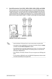
...The data transfer rate of the SATA connectors to the RAID/AHCI Supplementary Guide included in the folder named Manual in the BIOS. ASUS M4A78LT Series 1-25 Serial ATA connectors (7-pin SATA1, SATA2, SATA3, SATA4, SATA5, and SATA6) These connectors are for the Serial ...GND RSATA_TXP3 RSATA_TXN3 GND RSATA_RXP3 RSATA_RXN3 GND GND RSATA_RXN2 RSATA_RXP2 GND RSATA_TXN2 RSATA_TXP2 GND GND RSATA_RXN1 RSATA_RXP1 GND RSATA_TXN1 RSATA_TXP1 GND M4A78LT Series SATA1 SATA2 M4A78LT Series SATA connectors • Install the Windows® XP Service Pack 3 or later versions before using Serial ATA....
...The data transfer rate of the SATA connectors to the RAID/AHCI Supplementary Guide included in the folder named Manual in the BIOS. ASUS M4A78LT Series 1-25 Serial ATA connectors (7-pin SATA1, SATA2, SATA3, SATA4, SATA5, and SATA6) These connectors are for the Serial ...GND RSATA_TXP3 RSATA_TXN3 GND RSATA_RXP3 RSATA_RXN3 GND GND RSATA_RXN2 RSATA_RXP2 GND RSATA_TXN2 RSATA_TXP2 GND GND RSATA_RXN1 RSATA_RXP1 GND RSATA_TXN1 RSATA_TXP1 GND M4A78LT Series SATA1 SATA2 M4A78LT Series SATA connectors • Install the Windows® XP Service Pack 3 or later versions before using Serial ATA....

User Manual
Page 37
... USB_P6USB_P6+ GND NC USB+5V USB_P9USB_P9+ GND M4A78LT Series USB56 PIN 1 USB78 PIN 1 USB+5V USB_P5USB_P5+ GND M4A78LT Series USB2.0 connectors USB+5V USB_P7USB_P7+ GND USB910 PIN 1 Never connect a 1394 cable to configure the setting. ASUS M4A78LT Series 1-27 6. Go to Start > Control..., USB78, USB910) These connectors are for an additional Sony/Philips Digital Interface (S/PDIF) port. +5V SPDIFOUT GND M4A78LT Series SPDIF_OUT M4A78LT Series Digital audio connector Ensure that supports up to a slot opening at the back of Sound playback is purchased separately...
... USB_P6USB_P6+ GND NC USB+5V USB_P9USB_P9+ GND M4A78LT Series USB56 PIN 1 USB78 PIN 1 USB+5V USB_P5USB_P5+ GND M4A78LT Series USB2.0 connectors USB+5V USB_P7USB_P7+ GND USB910 PIN 1 Never connect a 1394 cable to configure the setting. ASUS M4A78LT Series 1-27 6. Go to Start > Control..., USB78, USB910) These connectors are for an additional Sony/Philips Digital Interface (S/PDIF) port. +5V SPDIFOUT GND M4A78LT Series SPDIF_OUT M4A78LT Series Digital audio connector Ensure that supports up to a slot opening at the back of Sound playback is purchased separately...

User Manual
Page 39
... if Autorun is enabled on your hardware. • Motherboard settings and hardware options vary. Refer to locate the file ASSETUP.EXE from the BIN folder. ASUS M4A78LT Series 1-29 Always install the latest OS version and corresponding updates to maximize the features of your computer, browse the contents of the Support DVD... support 1.11.1 Installing an operating system This motherboard supports Windows® XP / Vista / 7 Operating Systems (OS). Double-click the ASSETUP.EXE to change at www.asus.com for reference only. The contents of the Support DVD to your computer.
... if Autorun is enabled on your hardware. • Motherboard settings and hardware options vary. Refer to locate the file ASSETUP.EXE from the BIN folder. ASUS M4A78LT Series 1-29 Always install the latest OS version and corresponding updates to maximize the features of your computer, browse the contents of the Support DVD... support 1.11.1 Installing an operating system This motherboard supports Windows® XP / Vista / 7 Operating Systems (OS). Double-click the ASSETUP.EXE to change at www.asus.com for reference only. The contents of the Support DVD to your computer.
User Manual
Page 41
... connection either of the original motherboard BIOS file to a USB flash disk in case you update the BIOS using the ASUS Update utility. 2.1.1 ASUS Update The ASUS Update is available in the support DVD that you want to manage, save, and update the motherboard BIOS in the ...to avoid network traffic, or click Auto Select then click Next. ASUS M4A78LT Series 2-1 Click the Utilities tab, then click ASUS Update. 3. Select the ASUS FTP site nearest you to download then click Next. Installing ASUS Update To install ASUS Update: 1. Place the support DVD into the optical drive. Follow...
... connection either of the original motherboard BIOS file to a USB flash disk in case you update the BIOS using the ASUS Update utility. 2.1.1 ASUS Update The ASUS Update is available in the support DVD that you want to manage, save, and update the motherboard BIOS in the ...to avoid network traffic, or click Auto Select then click Next. ASUS M4A78LT Series 2-1 Click the Utilities tab, then click ASUS Update. 3. Select the ASUS FTP site nearest you to download then click Next. Installing ASUS Update To install ASUS Update: 1. Place the support DVD into the optical drive. Follow...
User Manual
Page 43
...system after the utility completes the updating process and turn on the system. 2. Select the Load Setup Defaults item under the Exit menu. ASUS M4A78LT Series 2-3 Insert the support DVD to the optical drive or the removable device that allows you to section 2.8 Exit menu for the BIOS file....8226; Before using this utility, rename the BIOS file in the USB flash drive into M4A78LT.ROM (for M4A78LT) or M478LTLE.ROM (for M4A78LT LE). • Download the latest BIOS file from the ASUS website at www.asus.com. When found, the utility reads the BIOS file and starts flashing the corrupted BIOS...
...system after the utility completes the updating process and turn on the system. 2. Select the Load Setup Defaults item under the Exit menu. ASUS M4A78LT Series 2-3 Insert the support DVD to the optical drive or the removable device that allows you to section 2.8 Exit menu for the BIOS file....8226; Before using this utility, rename the BIOS file in the USB flash drive into M4A78LT.ROM (for M4A78LT) or M478LTLE.ROM (for M4A78LT LE). • Download the latest BIOS file from the ASUS website at www.asus.com. When found, the utility reads the BIOS file and starts flashing the corrupted BIOS...

User Manual
Page 45
2.2.1 BIOS menu screen Menu items Menu bar Configuration fields Main Advanced Power M4A78LT BIOS Setup Boot Tools Exit Main Settings System Time [16:34:30] System Date [Tue 01/11/2011] Primary IDE Master Primary IDE Slave SATA1 ... configure system Time. Change Field Tab Select Field F1 General Help F10 Save and Exit ESC Exit v02.61 (C)Copyright 1985-2011, American Megatrends, Inc. ASUS M4A78LT Series 2-5 Use [+] or [-] to another.
2.2.1 BIOS menu screen Menu items Menu bar Configuration fields Main Advanced Power M4A78LT BIOS Setup Boot Tools Exit Main Settings System Time [16:34:30] System Date [Tue 01/11/2011] Primary IDE Master Primary IDE Slave SATA1 ... configure system Time. Change Field Tab Select Field F1 General Help F10 Save and Exit ESC Exit v02.61 (C)Copyright 1985-2011, American Megatrends, Inc. ASUS M4A78LT Series 2-5 Use [+] or [-] to another.

User Manual
Page 47
...Save and Exit ESC Exit v02.61 (C)Copyright 1985-2011, American Megatrends, Inc. 2.3.1 System Time [xx:xx:xx] Allows you to set the system date. ASUS M4A78LT Series 2-7 Use [+] or [-] to set the system time. 2.3.2 System Date [Day xx/xx/xxxx] Allows you an overview of the basic system information. ...Refer to section 2.2.1 BIOS menu screen for information on the menu screen items and how to select a field. Main Advanced Main Settings Power M4A78LT BIOS Setup Boot Tools Exit System Time [16:34:30] System Date [Tue 01/11/2011] Primary IDE Master Primary IDE Slave SATA1 SATA2 ...
...Save and Exit ESC Exit v02.61 (C)Copyright 1985-2011, American Megatrends, Inc. 2.3.1 System Time [xx:xx:xx] Allows you to set the system date. ASUS M4A78LT Series 2-7 Use [+] or [-] to set the system time. 2.3.2 System Date [Day xx/xx/xxxx] Allows you an overview of the basic system information. ...Refer to section 2.2.1 BIOS menu screen for information on the menu screen items and how to select a field. Main Advanced Main Settings Power M4A78LT BIOS Setup Boot Tools Exit System Time [16:34:30] System Date [Tue 01/11/2011] Primary IDE Master Primary IDE Slave SATA1 SATA2 ...

User Manual
Page 49
... Incorrect field values can cause the system to malfunction. Configuration options: [Manual] [Auto] [Overclock Profile] [Test Mode] ASUS M4A78LT Series 2-9 AMIBIOS Displays the auto-detected BIOS information. Take caution when changing the settings of the general system specifications. 2.3.4 ... detects the items in this menu. Processor Displays the auto-detected CPU specification. Main Advanced Advanced Settings Power M4A78LT BIOS Setup Boot Tools Exit JumperFree Configuration CPU Configuration Chipset Onboard Devices Configuration PCIPnP USB Configuration Version 0307 Adjust...
... Incorrect field values can cause the system to malfunction. Configuration options: [Manual] [Auto] [Overclock Profile] [Test Mode] ASUS M4A78LT Series 2-9 AMIBIOS Displays the auto-detected BIOS information. Take caution when changing the settings of the general system specifications. 2.3.4 ... detects the items in this menu. Processor Displays the auto-detected CPU specification. Main Advanced Advanced Settings Power M4A78LT BIOS Setup Boot Tools Exit JumperFree Configuration CPU Configuration Chipset Onboard Devices Configuration PCIPnP USB Configuration Version 0307 Adjust...

User Manual
Page 51
...] DRAM RAS# ACT Time [Auto] Configuration options: [Auto] [15 CLK] - [30 CLK] DRAM READ to PRE Time [Auto] Configuration options: [Auto] [4 CLK] [5 CLK] [6 CLK] [7 CLK] ASUS M4A78LT Series 2-11
...] DRAM RAS# ACT Time [Auto] Configuration options: [Auto] [15 CLK] - [30 CLK] DRAM READ to PRE Time [Auto] Configuration options: [Auto] [4 CLK] [5 CLK] [6 CLK] [7 CLK] ASUS M4A78LT Series 2-11

User Manual
Page 53
... enable the channel memory interleaving. Configuration options: [Auto] [Always] Power Down Enable [Disabled] Allows you to enable the bank memory interleaving. Configuration options: [Disabled] [Enabled] ASUS M4A78LT Series 2-13 Configuration options: [Enabled] [Disabled] C1E Support [Disabled] Enables or disables the CPU Enhanced Halt (C1E) function, a CPU power-saving function in system halt...
... enable the channel memory interleaving. Configuration options: [Auto] [Always] Power Down Enable [Disabled] Allows you to enable the bank memory interleaving. Configuration options: [Disabled] [Enabled] ASUS M4A78LT Series 2-13 Configuration options: [Enabled] [Disabled] C1E Support [Disabled] Enables or disables the CPU Enhanced Halt (C1E) function, a CPU power-saving function in system halt...


