User Manual
Page 7
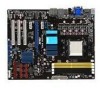
5. 從 CPU PnP 6. 請確認 CPU CPU CPU PnP 保護蓋 CPU CPU CPU CPU 7 A B A B
5. 從 CPU PnP 6. 請確認 CPU CPU CPU PnP 保護蓋 CPU CPU CPU CPU 7 A B A B
User Manual
Page 3
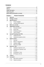
... Notices...vi Safety information vii About this guide vii M4A78 PRO specifications summary ix Chapter 1 Product introduction 1.1 Welcome 1-1 1.2 Package contents 1-1 1.3 Special features 1-1 1.3.1 Product highlights 1-1 1.3.2 Innovative ASUS features 1-2 1.4 Before you proceed 1-4 1.5 Motherboard overview 1-5 1.5.1 Placement direction 1-5 1.5.2 Screw holes 1-5 1.5.3 Motherboard layout 1-6 1.5.4 Layout contents 1-6 1.6 Central Processing Unit (CPU 1-7 1.6.1 Installing the CPU 1-7 1.6.2 Installing the heatsink and fan 1-8 1.7 System memory 1-10 1.7.1 Overview...
... Notices...vi Safety information vii About this guide vii M4A78 PRO specifications summary ix Chapter 1 Product introduction 1.1 Welcome 1-1 1.2 Package contents 1-1 1.3 Special features 1-1 1.3.1 Product highlights 1-1 1.3.2 Innovative ASUS features 1-2 1.4 Before you proceed 1-4 1.5 Motherboard overview 1-5 1.5.1 Placement direction 1-5 1.5.2 Screw holes 1-5 1.5.3 Motherboard layout 1-6 1.5.4 Layout contents 1-6 1.6 Central Processing Unit (CPU 1-7 1.6.1 Installing the CPU 1-7 1.6.2 Installing the heatsink and fan 1-8 1.7 System memory 1-10 1.7.1 Overview...

User Manual
Page 4
...31 1.11.2 Support DVD information 1-31 Chapter 2 BIOS information 2.1 Managing and updating your BIOS 2-1 2.1.1 Creating a bootable floppy disk 2-1 2.1.2 ASUS Update utility 2-2 2.1.3 ASUS EZ Flash 2 utility 2-3 2.1.4 AFUDOS utility 2-4 2.1.5 ASUS CrashFree BIOS 3 utility 2-5 2.2 BIOS setup program 2-6 2.2.1 BIOS menu screen 2-7 2.2.2 Menu bar 2-7 2.2.3 Navigation keys 2-8 2.2.4 Menu items...2.4.1 AI Overclocking 2-12 2.4.2 DRAM Frequency Control 2-12 2.4.3 HT Link Speed 2-13 2.4.4 Processor Voltage 2-15 2.4.5 CPU/NB Voltage 2-15 2.4.6 CPU VDDA Voltage 2-16 iv
...31 1.11.2 Support DVD information 1-31 Chapter 2 BIOS information 2.1 Managing and updating your BIOS 2-1 2.1.1 Creating a bootable floppy disk 2-1 2.1.2 ASUS Update utility 2-2 2.1.3 ASUS EZ Flash 2 utility 2-3 2.1.4 AFUDOS utility 2-4 2.1.5 ASUS CrashFree BIOS 3 utility 2-5 2.2 BIOS setup program 2-6 2.2.1 BIOS menu screen 2-7 2.2.2 Menu bar 2-7 2.2.3 Navigation keys 2-8 2.2.4 Menu items...2.4.1 AI Overclocking 2-12 2.4.2 DRAM Frequency Control 2-12 2.4.3 HT Link Speed 2-13 2.4.4 Processor Voltage 2-15 2.4.5 CPU/NB Voltage 2-15 2.4.6 CPU VDDA Voltage 2-16 iv

User Manual
Page 5
...HT Voltage 2-16 2.4.9 NB Voltage 2-16 2.4.10 NB 1.8V Voltage 2-16 2.4.11 SB Voltage 2-16 2.4.12 CPU Spread Spectrum 2-16 2.4.13 PCIE Spread Spectrum 2-16 2.4.14 SB Clock Spread Spectrum 2-16 2.5 Advanced menu 2-17 2.5.1 CPU Configuration 2-17 2.5.2 Chipset 2-18 2.5.3 Onboard Devices Configuration 2-20 2.5.4 USB Configuration 2-21 2.6 Power menu 2-21...Configuration 2-22 2.6.6 Hardware Monitor 2-23 2.7 Boot menu 2-24 2.7.1 Boot Device Priority 2-24 2.7.2 Boot Settings Configuration 2-24 2.7.3 Security 2-25 2.8 Tools menu 2-26 2.8.1 ASUS EZ Flash 2 2-26 2.8.2 Express Gate 2-26...
...HT Voltage 2-16 2.4.9 NB Voltage 2-16 2.4.10 NB 1.8V Voltage 2-16 2.4.11 SB Voltage 2-16 2.4.12 CPU Spread Spectrum 2-16 2.4.13 PCIE Spread Spectrum 2-16 2.4.14 SB Clock Spread Spectrum 2-16 2.5 Advanced menu 2-17 2.5.1 CPU Configuration 2-17 2.5.2 Chipset 2-18 2.5.3 Onboard Devices Configuration 2-20 2.5.4 USB Configuration 2-21 2.6 Power menu 2-21...Configuration 2-22 2.6.6 Hardware Monitor 2-23 2.7 Boot menu 2-24 2.7.1 Boot Device Priority 2-24 2.7.2 Boot Settings Configuration 2-24 2.7.3 Security 2-25 2.8 Tools menu 2-26 2.8.1 ASUS EZ Flash 2 2-26 2.8.2 Express Gate 2-26...
User Manual
Page 9
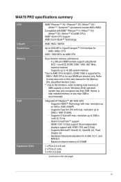
... (Qualified Vendors Lists). ** Due to 1920 x 1080 (1080P) - Refer to www.asus.com or this user manual for one DIMM per channel only. Integrated ATI Radeon™ HD 3200 GPU - Supports Microsoft® DirectX 10, OpenGL 2.0, Pixel Shader 4.0 - M4A78 PRO specifications summary CPU Chipset System bus Memory VGA Expansion Slots AMD® Phenom™...
... (Qualified Vendors Lists). ** Due to 1920 x 1080 (1080P) - Refer to www.asus.com or this user manual for one DIMM per channel only. Integrated ATI Radeon™ HD 3200 GPU - Supports Microsoft® DirectX 10, OpenGL 2.0, Pixel Shader 4.0 - M4A78 PRO specifications summary CPU Chipset System bus Memory VGA Expansion Slots AMD® Phenom™...
User Manual
Page 11
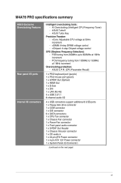
... Tuner) - M4A78 PRO specifications summary ASUS Exclusive Overclocking Features Rear panel I/O ports Internal I /O 4 x USB connectors support additional 8 USB ports 1 x Floppy disk drive connector 1 x COM connector 1 x IDE connector 6 x SATA connectors 1 x CPU Fan connector 1 x Chassis Fan connector 1 x Power Fan connector 1 x Front panel audio connector 1 x S/PDIF Out Header 1 x Chassis Intrusion connector 1 x CD audio in 1 x 24-pin ATX Power...
... Tuner) - M4A78 PRO specifications summary ASUS Exclusive Overclocking Features Rear panel I/O ports Internal I /O 4 x USB connectors support additional 8 USB ports 1 x Floppy disk drive connector 1 x COM connector 1 x IDE connector 6 x SATA connectors 1 x CPU Fan connector 1 x Chassis Fan connector 1 x Power Fan connector 1 x Front panel audio connector 1 x S/PDIF Out Header 1 x Chassis Intrusion connector 1 x CD audio in 1 x 24-pin ATX Power...

User Manual
Page 14
... Hybrid CrossFireX Technology is supported per channel. ASUS M4A78 PRO also features an extra 1-phase power for the Hybrid CrossfireX selected GPUs. 1.3.2 Innovative ASUS features ASUS Power Solution ASUS 4+1 Phase Power Design To fully unleash the next-generation AM3 CPU's potential, ASUS M4A78 PRO motherboard has adopted a brand-new 4-phase VRM power design. ASUS Anti-Surge This special design prevents expensive devices...
... Hybrid CrossFireX Technology is supported per channel. ASUS M4A78 PRO also features an extra 1-phase power for the Hybrid CrossfireX selected GPUs. 1.3.2 Innovative ASUS features ASUS Power Solution ASUS 4+1 Phase Power Design To fully unleash the next-generation AM3 CPU's potential, ASUS M4A78 PRO motherboard has adopted a brand-new 4-phase VRM power design. ASUS Anti-Surge This special design prevents expensive devices...
User Manual
Page 18
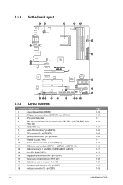
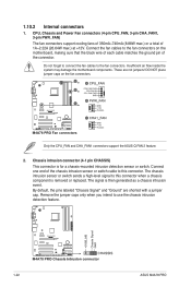
... Power Fan connectors (4-pin CPU_FAN, 3-pin CHA_FAN1, 3-pin PWR_FAN) 5. Onboard LED (SB_PWR) 10. ATX power connectors (24-pin EATXPWR, 4-pin ATX12V) 3. CPU socket AM2+/AM2 4. IDE connector (40-1 pin PRI_IDE) 8. Optical drive audio in connector (4-pin CD) 17... RTC RAM (CLRTC) 14. 1.5.3 Motherboard layout 1.5.4 Layout contents Connectors/Jumpers/Slots 1. Keyboard power (3-pin KBPWR) 2. DDR2 DIMM slots 6. Serial port connector (10-1 pin COM1) Page 1-18 1-23 1-7 1-22 1-10 1-25 1-24 1-26 1-4 1-22 1-18 1-27 1-17 1-27 1-28 1-28 1-29 1-29 1-6 ASUS M4A78 PRO
... Power Fan connectors (4-pin CPU_FAN, 3-pin CHA_FAN1, 3-pin PWR_FAN) 5. Onboard LED (SB_PWR) 10. ATX power connectors (24-pin EATXPWR, 4-pin ATX12V) 3. CPU socket AM2+/AM2 4. IDE connector (40-1 pin PRI_IDE) 8. Optical drive audio in connector (4-pin CD) 17... RTC RAM (CLRTC) 14. 1.5.3 Motherboard layout 1.5.4 Layout contents Connectors/Jumpers/Slots 1. Keyboard power (3-pin KBPWR) 2. DDR2 DIMM slots 6. Serial port connector (10-1 pin COM1) Page 1-18 1-23 1-7 1-22 1-10 1-25 1-24 1-26 1-4 1-22 1-18 1-27 1-17 1-27 1-28 1-28 1-29 1-29 1-6 ASUS M4A78 PRO
User Manual
Page 19
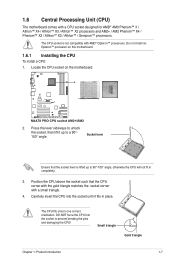
... only in place. DO NOT force the CPU into the socket until it up to prevent bending the pins and damaging the CPU! Locate the CPU socket on this motherboard. 1.6.1 Installing the CPU To install a CPU: 1. Position the CPU above the socket such that the socket lever is not compatible ...with AMD® Opteron™ processors. Carefully insert the CPU into the socket to 90°-...
... only in place. DO NOT force the CPU into the socket until it up to prevent bending the pins and damaging the CPU! Locate the CPU socket on this motherboard. 1.6.1 Installing the CPU To install a CPU: 1. Position the CPU above the socket such that the socket lever is not compatible ...with AMD® Opteron™ processors. Carefully insert the CPU into the socket to 90°-...
User Manual
Page 20
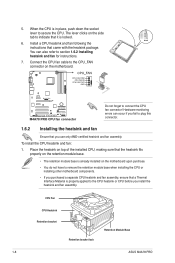
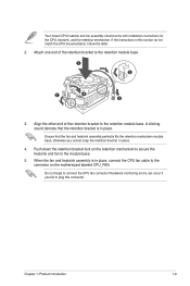
... heatsink and fan assembly. Do not forget to the CPU_FAN connector on the motherboard. To install the CPU heatsink and fan: 1. CPU Fan CPU Heatsink Retention bracket Retention bracket lock Retention Module Base 1-8 ASUS M4A78 PRO When the CPU is properly applied to secure the CPU. Hardware monitoring errors can also refer to plug this connector. 1.6.2 Installing the heatsink...
... heatsink and fan assembly. Do not forget to the CPU_FAN connector on the motherboard. To install the CPU heatsink and fan: 1. CPU Fan CPU Heatsink Retention bracket Retention bracket lock Retention Module Base 1-8 ASUS M4A78 PRO When the CPU is properly applied to secure the CPU. Hardware monitoring errors can also refer to plug this connector. 1.6.2 Installing the heatsink...
User Manual
Page 21
... retention bracket is in place. 4. Hardware monitoring errors can occur if you cannot snap the retention bracket in place, connect the CPU fan cable to the connector on the retention mechanism to secure the heatsink and fan to the retention module base. 1 2 3...CPU documentation, follow the latter. 2. Your boxed CPU heatsink and fan assembly should come with installation instructions for the CPU, heatsink, and the retention mechanism. Chapter 1: Product introduction 1-9 When the fan and heatsink assembly is in this connector. Push down the retention bracket lock on the motherboard...
... retention bracket is in place. 4. Hardware monitoring errors can occur if you cannot snap the retention bracket in place, connect the CPU fan cable to the connector on the retention mechanism to secure the heatsink and fan to the retention module base. 1 2 3...CPU documentation, follow the latter. 2. Your boxed CPU heatsink and fan assembly should come with installation instructions for the CPU, heatsink, and the retention mechanism. Chapter 1: Product introduction 1-9 When the fan and heatsink assembly is in this connector. Push down the retention bracket lock on the motherboard...
User Manual
Page 23
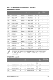
...8226; • • • • • • • • • • • Due to AM2+ CPU limitation, only one DDR2 1066 DIMM is supported per channel.When four DDR2 1066 DIMMs are installed, all DIMMs run at 800Mhz frequency by default...• • • • • • • • • • • Chapter 1: Product introduction 1-11 M4A78 PRO Motherboard Qualified Vendors Lists (QVL) DDR2-1066MHz capability Vendor Part No. A-DATA A-DATA Apacer Apacer G.SKILL G.SKILL G.SKILL GEIL GEIL GEIL GEIL Kingmax Kingston Kingston...
...8226; • • • • • • • • • • • Due to AM2+ CPU limitation, only one DDR2 1066 DIMM is supported per channel.When four DDR2 1066 DIMMs are installed, all DIMMs run at 800Mhz frequency by default...• • • • • • • • • • • Chapter 1: Product introduction 1-11 M4A78 PRO Motherboard Qualified Vendors Lists (QVL) DDR2-1066MHz capability Vendor Part No. A-DATA A-DATA Apacer Apacer G.SKILL G.SKILL G.SKILL GEIL GEIL GEIL GEIL Kingmax Kingston Kingston...

User Manual
Page 29
... of date, time, and system setup parameters by erasing the CMOS RTC RAM data. Move the jumper cap from pins 1-2 (default) to overclocking, use the C.P.R. (CPU Parameter Recall) feature. After the CMOS clearance, reinstall the battery. • You do not help, remove the onboard battery and move the cap back to...
... of date, time, and system setup parameters by erasing the CMOS RTC RAM data. Move the jumper cap from pins 1-2 (default) to overclocking, use the C.P.R. (CPU Parameter Recall) feature. After the CMOS clearance, reinstall the battery. • You do not help, remove the onboard battery and move the cap back to...
User Manual
Page 30
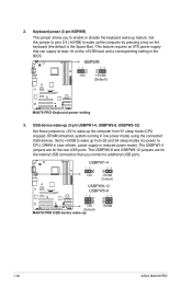
... these jumpers to +5V to additional USB ports. 1-18 ASUS M4A78 PRO The USBPW1-4 jumpers are for the rear USB ports. This feature requires an ATX power supply that you to wake up the computer from S3 and S4 sleep modes (no power to CPU, DRAM in slow refresh, power supply in low power mode... lead, and a corresponding setting in the BIOS. 3. Set this jumper to pins 2-3 (+5VSB) to enable or disable the keyboard wake-up from S1 sleep mode (CPU stopped, DRAM refreshed, system running in reduced power mode). Set to +5VSB to wake up feature. 2.
... these jumpers to +5V to additional USB ports. 1-18 ASUS M4A78 PRO The USBPW1-4 jumpers are for the rear USB ports. This feature requires an ATX power supply that you to wake up the computer from S3 and S4 sleep modes (no power to CPU, DRAM in slow refresh, power supply in low power mode... lead, and a corresponding setting in the BIOS. 3. Set this jumper to pins 2-3 (+5VSB) to enable or disable the keyboard wake-up from S1 sleep mode (CPU stopped, DRAM refreshed, system running in reduced power mode). Set to +5VSB to wake up feature. 2.
User Manual
Page 32
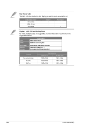
CPU DIMM Suggested list AMD® Athlon 4400+ DDR2 800 (1GB or higher) BIOS setup Playback software Frame Buffer Size--256MB or higher CyberLink® PowerDVD 7.3 (...-protected clips HD-DVD Blu-Ray Best resolution Windows XP Windows Vista 1920 x 1080p 1920 x 1080p 1920 x 1080p 1280 x 1080p 1280 x 1080p 1280 x 1080p 1-20 ASUS M4A78 PRO Dual display table This table indicates whether the dual display you follow the system requirements in the suggested list below. Dual display output DVI + D-Sub...
CPU DIMM Suggested list AMD® Athlon 4400+ DDR2 800 (1GB or higher) BIOS setup Playback software Frame Buffer Size--256MB or higher CyberLink® PowerDVD 7.3 (...-protected clips HD-DVD Blu-Ray Best resolution Windows XP Windows Vista 1920 x 1080p 1920 x 1080p 1920 x 1080p 1280 x 1080p 1280 x 1080p 1280 x 1080p 1-20 ASUS M4A78 PRO Dual display table This table indicates whether the dual display you follow the system requirements in the suggested list below. Dual display output DVI + D-Sub...
User Manual
Page 34
...intend to the fan connectors. Insufficient air flow inside the system may damage the motherboard components. Do not forget to connect the fan cables to use the chassis intrusion detection feature. 1-22 ASUS M4A78 PRO By default, the pins labeled "Chassis Signal" and "Ground" are not jumpers!... The chassis intrusion sensor or switch sends a high-level signal to this connector. The signal is then generated as a chassis intrusion event. CPU, Chassis and Power Fan connectors (4-pin CPU_FAN, 3-pin CHA_FAN1, 3-pin PWR_FAN) The fan connectors support cooling fans of 350mA~740mA (8.88W max...
...intend to the fan connectors. Insufficient air flow inside the system may damage the motherboard components. Do not forget to connect the fan cables to use the chassis intrusion detection feature. 1-22 ASUS M4A78 PRO By default, the pins labeled "Chassis Signal" and "Ground" are not jumpers!... The chassis intrusion sensor or switch sends a high-level signal to this connector. The signal is then generated as a chassis intrusion event. CPU, Chassis and Power Fan connectors (4-pin CPU_FAN, 3-pin CHA_FAN1, 3-pin PWR_FAN) The fan connectors support cooling fans of 350mA~740mA (8.88W max...

User Manual
Page 55
... 10 configuration from the Serial ATA hard disk drives, set this menu. BIOS Information Displays the auto-detected BIOS information. Processor Displays the auto-detected CPU specification.
... 10 configuration from the Serial ATA hard disk drives, set this menu. BIOS Information Displays the auto-detected BIOS information. Processor Displays the auto-detected CPU specification.

User Manual
Page 56
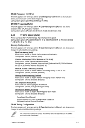
... on the motherboard. Configuration options: [Auto] [8.00x] [8.50x] [9.00x] [9.50x] [10.00x] [10.50x] [11.00x] FSB Frequency [XXX] Displays the frequency sent by the clock generator to adjust the ratio between CPU Core Clock and FSB Frequency. The default values of CPU overclocking options to [Manual]. Configuration options: [Auto] [Manual] 2-12 ASUS M4A78 PRO BIOS...
... on the motherboard. Configuration options: [Auto] [8.00x] [8.50x] [9.00x] [9.50x] [10.00x] [10.50x] [11.00x] FSB Frequency [XXX] Displays the frequency sent by the clock generator to adjust the ratio between CPU Core Clock and FSB Frequency. The default values of CPU overclocking options to [Manual]. Configuration options: [Auto] [Manual] 2-12 ASUS M4A78 PRO BIOS...
User Manual
Page 57
Configuration options: [Disabled] [Auto] Channel Interleaving [XOR of Address bit [20:16, 6]] Allows you to set the CPU-Northbridge HyperTransport link speed. Configuration options: [Disabled] [Enabled] Memory Hole Remapping [Enabled] Allows you enable the Power Down Enable...12] [XOR of Address bits [20:16, 6] [XOR of the CPU frequency multiplier. Configuration options: [Auto] [Enabled] [Disabled] Power Down Enable [Disabled] Allows you install on the motherboard. Configuration options: [667MHz] [800MHz] [1067MHz] CPU/NB Frequency [Auto] This item appears only when you set the AI ...
Configuration options: [Disabled] [Auto] Channel Interleaving [XOR of Address bit [20:16, 6]] Allows you to set the CPU-Northbridge HyperTransport link speed. Configuration options: [Disabled] [Enabled] Memory Hole Remapping [Enabled] Allows you enable the Power Down Enable...12] [XOR of Address bits [20:16, 6] [XOR of the CPU frequency multiplier. Configuration options: [Auto] [Enabled] [Disabled] Power Down Enable [Disabled] Allows you install on the motherboard. Configuration options: [667MHz] [800MHz] [1067MHz] CPU/NB Frequency [Auto] This item appears only when you set the AI ...

User Manual
Page 59
... typing the desired values using the keyboard and press the key. 2.4.4 Processor Voltage [Auto] Allows you to set the CPU VCore voltage. 2.4.5 CPU/NB Voltage [Auto] Allows you set the voltage between the CPU and Northbridge. Chapter 2: BIOS setup 2-15 item to adjust the value. You can also use the and keys to...
... typing the desired values using the keyboard and press the key. 2.4.4 Processor Voltage [Auto] Allows you to set the CPU VCore voltage. 2.4.5 CPU/NB Voltage [Auto] Allows you set the voltage between the CPU and Northbridge. Chapter 2: BIOS setup 2-15 item to adjust the value. You can also use the and keys to...


