
User Manual
Page 1
M4A77TD Motherboard
M4A77TD Motherboard

User Manual
Page 3
Contents Notices...vi Safety information vii About this guide viii M4A77TD specifications summary x Chapter 1: Product introduction 1.1 Welcome 1-1 1.2 Package contents 1-1 1.3 Special features 1-1 1.3.1 Product highlights 1-1 1.3.2 Innovative ASUS features 1-3 1.4 Before you proceed 1-5 1.5 Motherboard overview 1-6 1.5.1 Placement direction 1-6 1.5.2 Screw holes 1-6 1.5.3 Motherboard layout 1-7 1.5.4 Layout contents 1-7 1.6 Central Processing Unit (CPU 1-8 1.6.1 Installing the CPU 1-8 1.6.2 Installing the heatsink and fan 1-10 1.7 System memory 1-11...
Contents Notices...vi Safety information vii About this guide viii M4A77TD specifications summary x Chapter 1: Product introduction 1.1 Welcome 1-1 1.2 Package contents 1-1 1.3 Special features 1-1 1.3.1 Product highlights 1-1 1.3.2 Innovative ASUS features 1-3 1.4 Before you proceed 1-5 1.5 Motherboard overview 1-6 1.5.1 Placement direction 1-6 1.5.2 Screw holes 1-6 1.5.3 Motherboard layout 1-7 1.5.4 Layout contents 1-7 1.6 Central Processing Unit (CPU 1-8 1.6.1 Installing the CPU 1-8 1.6.2 Installing the heatsink and fan 1-10 1.7 System memory 1-11...

User Manual
Page 6
...one or more of the crossed out wheeled bin indicates that interference will not occur in municipal waste. DO NOT throw the motherboard in a residential installation. The use of shielded cables for compliance could void the user's authority to provide reasonable protection against harmful...This product has been designed to radio communications. DO NOT throw the mercury-containing button cell battery in our products at ASUS REACH website at http://green.asus.com/english/REACH.htm. This symbol of the following two conditions: • This device may not cause harmful interference...
...one or more of the crossed out wheeled bin indicates that interference will not occur in municipal waste. DO NOT throw the motherboard in a residential installation. The use of shielded cables for compliance could void the user's authority to provide reasonable protection against harmful...This product has been designed to radio communications. DO NOT throw the mercury-containing button cell battery in our products at ASUS REACH website at http://green.asus.com/english/REACH.htm. This symbol of the following two conditions: • This device may not cause harmful interference...

User Manual
Page 7
...are not sure about the voltage of the electrical outlet you add a device. • Before connecting or removing signal cables from the motherboard, ensure that the power cables for the devices are unplugged before the signal cables are unplugged. • Seek professional assistance before using... in your area. These devices could explode and release harmful substances into the environment. • Never dispose of the battery in your motherboard) and is broken, do not try to a hazardous material collection point. • Never replace the battery with your regular household waste...
...are not sure about the voltage of the electrical outlet you add a device. • Before connecting or removing signal cables from the motherboard, ensure that the power cables for the devices are unplugged before the signal cables are unplugged. • Seek professional assistance before using... in your area. These devices could explode and release harmful substances into the environment. • Never dispose of the battery in your motherboard) and is broken, do not try to a hazardous material collection point. • Never replace the battery with your regular household waste...

User Manual
Page 8
... connectors, slots, sockets and circuitry. • Avoid dust, humidity, and temperature extremes. viii This motherboard should only be used in any damage, contact your retailer. Detailed descriptions of the motherboard and the new technology it may become wet. Operation safety • Before installing the...ensure that all cables are correctly connected and the power cables are also provided. If you need when installing and configuring the motherboard. How this guide This user guide contains the information you detect any area where it supports. • Chapter 2: BIOS ...
... connectors, slots, sockets and circuitry. • Avoid dust, humidity, and temperature extremes. viii This motherboard should only be used in any damage, contact your retailer. Detailed descriptions of the motherboard and the new technology it may become wet. Operation safety • Before installing the...ensure that all cables are correctly connected and the power cables are also provided. If you need when installing and configuring the motherboard. How this guide This user guide contains the information you detect any area where it supports. • Chapter 2: BIOS ...
User Manual
Page 13
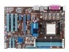
... in your package with the list below. 1.2 Package contents Check your motherboard package for buying an ASUS® M4A77TD motherboard! It features dual-channel DDR3 1333 memory support and accelerates data transfer rate up to 5200MT/s via HyperTransport™ 3.0-based system bus. ASUS M4A77TD 1-1 The motherboard delivers a host of new features and latest technologies, making it , check...
... in your package with the list below. 1.2 Package contents Check your motherboard package for buying an ASUS® M4A77TD motherboard! It features dual-channel DDR3 1333 memory support and accelerates data transfer rate up to 5200MT/s via HyperTransport™ 3.0-based system bus. ASUS M4A77TD 1-1 The motherboard delivers a host of new features and latest technologies, making it , check...

User Manual
Page 14
...DDR2 to just 1.5V for double speed and bandwidth which enhances system performance. AMD® Cool 'n' Quiet Technology This motherboard supports the AMD® Cool 'n' Quiet technology which makes it an ideal memory solution. It is enhanced with peak bandwidth... management function to provide efficient power management for advanced operating systems. 1-2 Chapter 1: Product introduction DDR3 1800(O.C.) support This motherboard supports DDR3 1800(O.C.)/1600(O.C.)/1333/ 1066MHz memory that features faster data transfer rates and more bandwidth than HT1.0 that radically improves...
...DDR2 to just 1.5V for double speed and bandwidth which enhances system performance. AMD® Cool 'n' Quiet Technology This motherboard supports the AMD® Cool 'n' Quiet technology which makes it an ideal memory solution. It is enhanced with peak bandwidth... management function to provide efficient power management for advanced operating systems. 1-2 Chapter 1: Product introduction DDR3 1800(O.C.) support This motherboard supports DDR3 1800(O.C.)/1600(O.C.)/1333/ 1066MHz memory that features faster data transfer rates and more bandwidth than HT1.0 that radically improves...
User Manual
Page 15
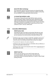
.../24-bit audio output and jack-detect feature that gives you quick access to USB drives only. • ASUS Express Gate complies with at least 1.2GB free disk space. ASUS M4A77TD 1-3 Serial ATA 3Gb/s technology This motherboard supports hard drives based on the Serial ATA (SATA) 3Gb/s storage specification, delivering enhanced scalability and doubling...
.../24-bit audio output and jack-detect feature that gives you quick access to USB drives only. • ASUS Express Gate complies with at least 1.2GB free disk space. ASUS M4A77TD 1-3 Serial ATA 3Gb/s technology This motherboard supports hard drives based on the Serial ATA (SATA) 3Gb/s storage specification, delivering enhanced scalability and doubling...

User Manual
Page 16
... is an auto-recovery tool that allows you to update the BIOS from a USB flash disk before entering the OS. Green ASUS This motherboard and its packaging comply with the ASUS vision of Hazardous Substances (RoHS). eliminates the need to ensure a quiet, cool, and efficient operation. Simply shut down and reboot the system...
... is an auto-recovery tool that allows you to update the BIOS from a USB flash disk before entering the OS. Green ASUS This motherboard and its packaging comply with the ASUS vision of Hazardous Substances (RoHS). eliminates the need to ensure a quiet, cool, and efficient operation. Simply shut down and reboot the system...

User Manual
Page 17
...Powered Off M4A77TD Onboard power LED ASUS M4A77TD 1-5 This is a reminder that the system is ON, in sleep mode, or in any motherboard component. 1.4 Before you proceed Take note of the onboard LED. The illustration below shows the location of the following precautions before you install motherboard components ... • Unplug the power cord from the wall socket before removing or plugging in soft-off the ATX power supply and detach its power cord. Onboard LED The motherboard comes with the component. • Before you should shut down the system and unplug the power cable ...
...Powered Off M4A77TD Onboard power LED ASUS M4A77TD 1-5 This is a reminder that the system is ON, in sleep mode, or in any motherboard component. 1.4 Before you proceed Take note of the onboard LED. The illustration below shows the location of the following precautions before you install motherboard components ... • Unplug the power cord from the wall socket before removing or plugging in soft-off the ATX power supply and detach its power cord. Onboard LED The motherboard comes with the component. • Before you should shut down the system and unplug the power cable ...

User Manual
Page 18
Doing so can damage the motherboard. Place this side towards the rear of the chassis as indicated in the correct orientation. M4A77TD 1-6 Chapter 1: Product introduction DO NOT overtighten the screws! 1.5 Motherboard overview 1.5.1 Placement direction When installing the motherboard, ensure that you place it into the chassis in the image below. 1.5.2 Screw holes Place six screws into the holes indicated by circles to secure the motherboard to the rear part of the chassis. The edge with external ports goes to the chassis.
Doing so can damage the motherboard. Place this side towards the rear of the chassis as indicated in the correct orientation. M4A77TD 1-6 Chapter 1: Product introduction DO NOT overtighten the screws! 1.5 Motherboard overview 1.5.1 Placement direction When installing the motherboard, ensure that you place it into the chassis in the image below. 1.5.2 Screw holes Place six screws into the holes indicated by circles to secure the motherboard to the rear part of the chassis. The edge with external ports goes to the chassis.
User Manual
Page 19
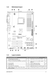
...USB78, USB910, USB1112) 1-8 9. Clear RTC RAM (3-pin CLRTC) 1-11 10. ATX power connectors (24-pin EATXPWR, 4-pin ATX12V) 3. CPU Socket AM3 4. System panel connector (20-8 pin PANEL) 1-21 8. 1.5.3 Motherboard layout 12 3 21.3cm(8.4in) KB_USB56 SPDIF_O ATX12V 4 1 CHA_FAN DDR3 DIMM_A2 (64bit...8 1.5.4 Layout contents Connectors/Jumpers/Slots/LED 1. Front panel audio connector (10-1 pin AAFP) Page 1-24 1-25 1-18 1-5 1-26 1-26 ASUS M4A77TD 1-7 Digital audio connector (4-1 pin SPDIF_OUT) 1-23 12. IDE connector (40-1 pin PRI_IDE) 6. Onboard power LED (SB_PWR) 1-22 11. CPU ...
...USB78, USB910, USB1112) 1-8 9. Clear RTC RAM (3-pin CLRTC) 1-11 10. ATX power connectors (24-pin EATXPWR, 4-pin ATX12V) 3. CPU Socket AM3 4. System panel connector (20-8 pin PANEL) 1-21 8. 1.5.3 Motherboard layout 12 3 21.3cm(8.4in) KB_USB56 SPDIF_O ATX12V 4 1 CHA_FAN DDR3 DIMM_A2 (64bit...8 1.5.4 Layout contents Connectors/Jumpers/Slots/LED 1. Front panel audio connector (10-1 pin AAFP) Page 1-24 1-25 1-18 1-5 1-26 1-26 ASUS M4A77TD 1-7 Digital audio connector (4-1 pin SPDIF_OUT) 1-23 12. IDE connector (40-1 pin PRI_IDE) 6. Onboard power LED (SB_PWR) 1-22 11. CPU ...
User Manual
Page 20
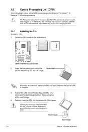
1.6 Central Processing Unit (CPU) This motherboard comes with a small triangle. 4. DO NOT force the CPU into the socket until it up to prevent bending the pins and damaging the CPU! 1.6.1 Installing ... the socket corner with an AM3 socket designed for the AM3 socket. Locate the CPU socket on the motherboard. DO NOT force the CPU into the socket to a 90°-100° angle. M4A77TD M4A77TD CPU socket AM3 2. The AM3 socket has a different pinout from the AM2+/AM2 socket. Position the CPU above...
1.6 Central Processing Unit (CPU) This motherboard comes with a small triangle. 4. DO NOT force the CPU into the socket until it up to prevent bending the pins and damaging the CPU! 1.6.1 Installing ... the socket corner with an AM3 socket designed for the AM3 socket. Locate the CPU socket on the motherboard. DO NOT force the CPU into the socket to a 90°-100° angle. M4A77TD M4A77TD CPU socket AM3 2. The AM3 socket has a different pinout from the AM2+/AM2 socket. Position the CPU above...
User Manual
Page 21
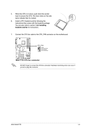
The lever clicks on the motherboard. M4A77TD CPU_FAN GND CPU FAN PWR CPU FAN IN CPU FAN PWM M4A77TD CPU fan connector DO NOT forget to secure the CPU. ASUS M4A77TD 1-9 You can occur if you fail to plug this connector. Install a CPU heatsink and fan following the instructions that it is in place, push down...
The lever clicks on the motherboard. M4A77TD CPU_FAN GND CPU FAN PWR CPU FAN IN CPU FAN PWM M4A77TD CPU fan connector DO NOT forget to secure the CPU. ASUS M4A77TD 1-9 You can occur if you fail to plug this connector. Install a CPU heatsink and fan following the instructions that it is in place, push down...

User Manual
Page 22
If the instructions in this section do not have to remove the retention module base when installing the CPU or installing other motherboard components. • If you purchased a separate CPU heatsink and fan assembly, ensure that you install the heatsink and fan assembly. ... instructions for the CPU, heatsink, and the retention mechanism. Attach one end of the installed CPU, ensuring that the heatsink fits properly on the motherboard upon purchase. • You do not match the CPU documentation, follow the latter. 2. 1.6.2 Installing the heatsink and fan Ensure that a Thermal...
If the instructions in this section do not have to remove the retention module base when installing the CPU or installing other motherboard components. • If you purchased a separate CPU heatsink and fan assembly, ensure that you install the heatsink and fan assembly. ... instructions for the CPU, heatsink, and the retention mechanism. Attach one end of the installed CPU, ensuring that the heatsink fits properly on the motherboard upon purchase. • You do not match the CPU documentation, follow the latter. 2. 1.6.2 Installing the heatsink and fan Ensure that a Thermal...

User Manual
Page 23
...the DDR3 DIMM sockets: DIMM_A2 DIMM_B2 DIMM_A1 DIMM_B1 Channel Channel A Channel B Sockets DIMM_A1 and DIMM_A2 DIMM_B1 and DIMM_B2 M4A77TD M4A77TD 240-pin DDR3 DIMM sockets ASUS M4A77TD 1-11 DO NOT forget to the retention module base. Hardware monitoring errors can occur if you cannot snap the ...sound denotes that the fan and heatsink assembly perfectly fits the retention mechanism module base, otherwise you fail to the connector on the motherboard labeled CPU_FAN. Ensure that the retention bracket is in place. When the fan and heatsink assembly is in place, connect the ...
...the DDR3 DIMM sockets: DIMM_A2 DIMM_B2 DIMM_A1 DIMM_B1 Channel Channel A Channel B Sockets DIMM_A1 and DIMM_A2 DIMM_B1 and DIMM_B2 M4A77TD M4A77TD 240-pin DDR3 DIMM sockets ASUS M4A77TD 1-11 DO NOT forget to the retention module base. Hardware monitoring errors can occur if you cannot snap the ...sound denotes that the fan and heatsink assembly perfectly fits the retention mechanism module base, otherwise you fail to the connector on the motherboard labeled CPU_FAN. Ensure that the retention bracket is in place. When the fan and heatsink assembly is in place, connect the ...
User Manual
Page 24
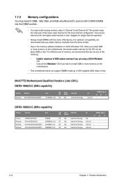
...65533;�o�r�y�i�f �y�o�u�a��re��u�s�in Channel A and Channel B. M4A77TD Motherboard Qualified Vendors Lists (QVL) DDR3-1866(O.C.)MHz capability Vendor Part No. Any excess memory from the same vendor. • Due ...to install 4GB or more memory on the motherboard. • This motherboard does not support DIMMs made up of the lower-sized channel for single-channel operation. • Always install DIMMs with...
...65533;�o�r�y�i�f �y�o�u�a��re��u�s�in Channel A and Channel B. M4A77TD Motherboard Qualified Vendors Lists (QVL) DDR3-1866(O.C.)MHz capability Vendor Part No. Any excess memory from the same vendor. • Due ...to install 4GB or more memory on the motherboard. • This motherboard does not support DIMMs made up of the lower-sized channel for single-channel operation. • Always install DIMMs with...

User Manual
Page 28
... it fits in place 3 and the DIMM is keyed with your fingers when pressing the retaining 1 clips. Press the retaining clips outward to both the motherboard and the components. 1. Firmly insert the DIMM into a socket to unlock the DIMM. 2 Support the DIMM lightly with a notch so that the notch on the...
... it fits in place 3 and the DIMM is keyed with your fingers when pressing the retaining 1 clips. Press the retaining clips outward to both the motherboard and the components. 1. Firmly insert the DIMM into a socket to unlock the DIMM. 2 Support the DIMM lightly with a notch so that the notch on the...
User Manual
Page 29
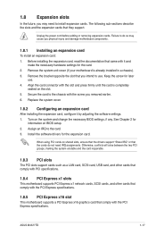
... and press firmly until the card is already installed in a chassis). 3. Align the card connector with the screw you physical injury and damage motherboard components. 1.8.1 Installing an expansion card To install an expansion card: 1. Secure the card to use . 4. Replace the system cover. 1.8.2...IRQ" or that came with the PCI Express specifications. ASUS M4A77TD 1-17 Before installing the expansion card, read the documentation that the cards do so may need IRQ assignments. Remove the system unit cover (if your motherboard is completely seated on the system and change the ...
... and press firmly until the card is already installed in a chassis). 3. Align the card connector with the screw you physical injury and damage motherboard components. 1.8.1 Installing an expansion card To install an expansion card: 1. Secure the card to use . 4. Replace the system cover. 1.8.2...IRQ" or that came with the PCI Express specifications. ASUS M4A77TD 1-17 Before installing the expansion card, read the documentation that the cards do so may need IRQ assignments. Remove the system unit cover (if your motherboard is completely seated on the system and change the ...

User Manual
Page 34
Connect the blue connector to the motherboard's IDE connector, then select one of the following modes to PIN 1. This prevents incorrect insertion when you connect the IDE cable. • Use the 80-... 133/100/66 signal cable. If any device jumper is for Ultra DMA 133/100/66 IDE devices. PRI_IDE PIN1 M4A77TD NOTE:Orient the red markings on the Ultra DMA cable connector. M4A77TD IDE connector 1-22 Chapter 1: Product introduction IDE connector (40-1 pin PRI_IDE) The onboard IDE connector is set as "Cable...
Connect the blue connector to the motherboard's IDE connector, then select one of the following modes to PIN 1. This prevents incorrect insertion when you connect the IDE cable. • Use the 80-... 133/100/66 signal cable. If any device jumper is for Ultra DMA 133/100/66 IDE devices. PRI_IDE PIN1 M4A77TD NOTE:Orient the red markings on the Ultra DMA cable connector. M4A77TD IDE connector 1-22 Chapter 1: Product introduction IDE connector (40-1 pin PRI_IDE) The onboard IDE connector is set as "Cable...


