User Manual
Page 10
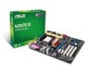
... 1 x PS/2 Keyboard/Mouse Combo port 1 x RJ45 port 6 x USB 2.0/1.1 ports 6-channel Audio I /O connectors BIOS Accessories Form Factor Support DVD ASUS Quiet Thermal Solution - ASUS Q-Fan ASUS EZ DIY - M3N78 SE specifications summary ASUS special features Back panel I/O ports Internal I /O ports 1 x LPT port 1 x COM port 3 x USB 2.0/1.1 connectors support additional... CPU Fan connectors 24-pin EATX power connector 4-pin ATX 12V power connector 8Mb Flash ROM, AMI BIOS, PnP, DMI2.0, WfM2.0, ACPI2.0, SM BIOS 2.5, ASUS EZ Flash 2 1 x Serial ATA cable 1 x Serial ATA power cable 1 x UltraDMA 133/...
... 1 x PS/2 Keyboard/Mouse Combo port 1 x RJ45 port 6 x USB 2.0/1.1 ports 6-channel Audio I /O connectors BIOS Accessories Form Factor Support DVD ASUS Quiet Thermal Solution - ASUS Q-Fan ASUS EZ DIY - M3N78 SE specifications summary ASUS special features Back panel I/O ports Internal I /O ports 1 x LPT port 1 x COM port 3 x USB 2.0/1.1 connectors support additional... CPU Fan connectors 24-pin EATX power connector 4-pin ATX 12V power connector 8Mb Flash ROM, AMI BIOS, PnP, DMI2.0, WfM2.0, ACPI2.0, SM BIOS 2.5, ASUS EZ Flash 2 1 x Serial ATA cable 1 x Serial ATA power cable 1 x UltraDMA 133/...
User Manual
Page 13
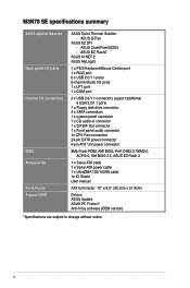
... 2-5 for details. See page 2-3 for details. Just simply restart the system, the BIOS would show the previous setting and then users can update your system. ASUS M3N78 SE 1-3 ASUS MyLogo2™ Turn your favorite photos into 256-color boot logos to personalize your BIOS only in line with the European Union's Restriction on the environment. CPU...
... 2-5 for details. See page 2-3 for details. Just simply restart the system, the BIOS would show the previous setting and then users can update your system. ASUS M3N78 SE 1-3 ASUS MyLogo2™ Turn your favorite photos into 256-color boot logos to personalize your BIOS only in line with the European Union's Restriction on the environment. CPU...
User Manual
Page 16
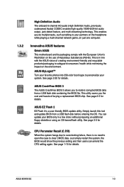
... 30.5cm(12.0in) USB34 2 LAN1_USB12 AUDIO Realtek 8211CL NVIDIA® MCP78D PCIEX16 SATA4 SATA3 SATA2 SATA1 5 PCIEX1_1 M3N78 SE PCIEX1_2 USB910 USB78 USB1112 Super I/O PCI1 6 PRI_IDE 7 PCI2 Lithium Cell 14 CMOS Power 8Mb BIOS 8 SPEAKER PCI3 ALC 662 AAFP SPDIF_OUT CD FLOPPY SB_PWR CLRTC F_PANEL 9 13 12 11 10 1.5.4 Layout contents Connectors...
... 30.5cm(12.0in) USB34 2 LAN1_USB12 AUDIO Realtek 8211CL NVIDIA® MCP78D PCIEX16 SATA4 SATA3 SATA2 SATA1 5 PCIEX1_1 M3N78 SE PCIEX1_2 USB910 USB78 USB1112 Super I/O PCI1 6 PRI_IDE 7 PCI2 Lithium Cell 14 CMOS Power 8Mb BIOS 8 SPEAKER PCI3 ALC 662 AAFP SPDIF_OUT CD FLOPPY SB_PWR CLRTC F_PANEL 9 13 12 11 10 1.5.4 Layout contents Connectors...
User Manual
Page 25
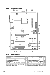
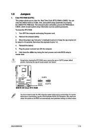
... position. For system failure due to pins 1-2. 4. Shut down the key during the boot process and enter BIOS setup to clear the Real Time Clock (RTC) RAM in CMOS, which include system setup information such as ... powers the RAM data in CMOS. Reinstall the battery. 5. Hold down and reboot the system so the BIOS can clear the CMOS memory of date, time, and system setup parameters by erasing the CMOS RTC RAM data...move the cap back to overclocking, use the CPU Parameter Recall (C.P.R) feature. ASUS M3N78 SE 1-15 1.9 Jumpers 1. Removing the cap will cause system boot failure!
... position. For system failure due to pins 1-2. 4. Shut down the key during the boot process and enter BIOS setup to clear the Real Time Clock (RTC) RAM in CMOS, which include system setup information such as ... powers the RAM data in CMOS. Reinstall the battery. 5. Hold down and reboot the system so the BIOS can clear the CMOS memory of date, time, and system setup parameters by erasing the CMOS RTC RAM data...move the cap back to overclocking, use the CPU Parameter Recall (C.P.R) feature. ASUS M3N78 SE 1-15 1.9 Jumpers 1. Removing the cap will cause system boot failure!
User Manual
Page 29
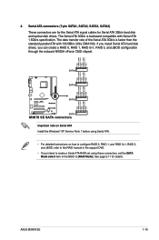
... RAID manual in the support DVD. • If you can create a RAID 0, RAID 1, RAID 0+1, RAID 5, and JBOD configuration through the onboard NVIDIA nForce 720D chipset. ASUS M3N78 SE 1-19 The Serial ATA 3Gb/s is faster than the standard parallel ATA with Serial ATA 1.5Gb/s specification. Serial ATA connectors (7-pin SATA1, SATA2, SATA3, SATA4... for details. If you install Serial ATA hard disk drives, you intend to create a Serial ATA RAID set the SATA Mode select item in the BIOS to [RAID Mode]. See page 2-11 for Serial ATA 3Gb/s hard disk and optical disk drives.
... RAID manual in the support DVD. • If you can create a RAID 0, RAID 1, RAID 0+1, RAID 5, and JBOD configuration through the onboard NVIDIA nForce 720D chipset. ASUS M3N78 SE 1-19 The Serial ATA 3Gb/s is faster than the standard parallel ATA with Serial ATA 1.5Gb/s specification. Serial ATA connectors (7-pin SATA1, SATA2, SATA3, SATA4... for details. If you install Serial ATA hard disk drives, you intend to create a Serial ATA RAID set the SATA Mode select item in the BIOS to [RAID Mode]. See page 2-11 for Serial ATA 3Gb/s hard disk and optical disk drives.
User Manual
Page 31
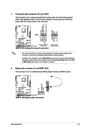
... (10-1 pin AAFP) This connector is for an additional Sony/Philips Digital Interface (S/PDIF) port(s). +5V SPDIFOUT GND M3N78 SE SPDIF_OUT M3N78 SE Digital audio connector ASUS M3N78 SE 1-21 Connect one end of the front panel audio I /O module that you want to connect a High Definition front ...M3N78 SE Analog front panel connector • We recommend that supports either High Definition Audio or AC`97 audio standard. 7. See section "2.4.3 Chipset" for a chassis-mounted front panel audio I /O module cable to this connector is set the Front Panel Select item in the BIOS...
... (10-1 pin AAFP) This connector is for an additional Sony/Philips Digital Interface (S/PDIF) port(s). +5V SPDIFOUT GND M3N78 SE SPDIF_OUT M3N78 SE Digital audio connector ASUS M3N78 SE 1-21 Connect one end of the front panel audio I /O module that you want to connect a High Definition front ...M3N78 SE Analog front panel connector • We recommend that supports either High Definition Audio or AC`97 audio standard. 7. See section "2.4.3 Chipset" for a chassis-mounted front panel audio I /O module cable to this connector is set the Front Panel Select item in the BIOS...
User Manual
Page 33
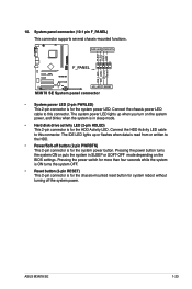
...) This 2-pin connector is for the chassis-mounted reset button for the system power LED. Ground Reset M3N78 SE F_PANEL PIN 1 HD_LED RESET M3N78 SE System panel connector • System power LED (2-pin PWRLED) This 2-pin connector is for system reboot... without turning off button (2-pin PWRBTN) This 2-pin connector is in SLEEP or SOFT-OFF mode depending on the BIOS ... connector (10-1 pin F_PANEL) This connector supports several chassis-mounted functions. ASUS M3N78 SE 1-23
...) This 2-pin connector is for the chassis-mounted reset button for the system power LED. Ground Reset M3N78 SE F_PANEL PIN 1 HD_LED RESET M3N78 SE System panel connector • System power LED (2-pin PWRLED) This 2-pin connector is for system reboot... without turning off button (2-pin PWRBTN) This 2-pin connector is in SLEEP or SOFT-OFF mode depending on the BIOS ... connector (10-1 pin F_PANEL) This connector supports several chassis-mounted functions. ASUS M3N78 SE 1-23
User Manual
Page 37
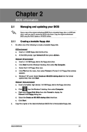
... floppy disk 1. b. e. Insert a formatted, high density 1.44 MB floppy disk to restore the BIOS in the future. Select the Create an MS-DOS startup disk check box. ASUS M3N78 SE 2-1 Windows® XP environment a. c. Chapter 2 BIOS information 2.1 Managing and updating your BIOS Save a copy of the following to the bootable floppy disk. DOS environment a. Select the...
... floppy disk 1. b. e. Insert a formatted, high density 1.44 MB floppy disk to restore the BIOS in the future. Select the Create an MS-DOS startup disk check box. ASUS M3N78 SE 2-1 Windows® XP environment a. c. Chapter 2 BIOS information 2.1 Managing and updating your BIOS Save a copy of the following to the bootable floppy disk. DOS environment a. Select the...
User Manual
Page 39
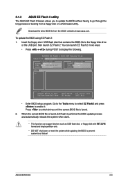
... to prevent system boot failure! Download the lates BIOS file from a floppy disk or a DOS‑based utility. Go to the Tools menu to select EZ Flash2 and press to the floppy disk drive or the USB port, then launch EZ Flash 2. ASUS M3N78 SE 2-3 Insert the floppy disk / USB flash disk... that contains the BIOS file to enable it. ASUSTek EZ Flash 2 BIOS ROM Utility V3.21 FLASH TYPE: MXIC 25L8005 Current ROM BOARD: M3N78 SE VER: 0204 (H:00 B:00) DATE: 08/27/2008 ...
... to prevent system boot failure! Download the lates BIOS file from a floppy disk or a DOS‑based utility. Go to the Tools menu to select EZ Flash2 and press to the floppy disk drive or the USB port, then launch EZ Flash 2. ASUS M3N78 SE 2-3 Insert the floppy disk / USB flash disk... that contains the BIOS file to enable it. ASUSTek EZ Flash 2 BIOS ROM Utility V3.21 FLASH TYPE: MXIC 25L8005 Current ROM BOARD: M3N78 SE VER: 0204 (H:00 B:00) DATE: 08/27/2008 ...
User Manual
Page 41
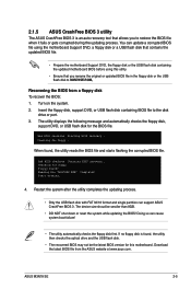
...Turn on the system. 2. Bad BIOS checksum. Download the latest BIOS file from a floppy disk To recover the BIOS: 1. Recovering the BIOS from the ASUS website at www.asus.com. Completed. The device size shoud be the latest BIOS version for floppy... Doing so can support ASUS CrashFree BIOS 3. Checking for this utility. &#... can cause system boot failure! • The utility automatically checks the floppy disk first. When found ! Bad BIOS checksum. Floppy found , the utility reads the BIOS file and starts flashing the corrupted BIOS file. ASUS M3N78 SE 2-5
...Turn on the system. 2. Bad BIOS checksum. Download the latest BIOS file from a floppy disk To recover the BIOS: 1. Recovering the BIOS from the ASUS website at www.asus.com. Completed. The device size shoud be the latest BIOS version for floppy... Doing so can support ASUS CrashFree BIOS 3. Checking for this utility. &#... can cause system boot failure! • The utility automatically checks the floppy disk first. When found ! Bad BIOS checksum. Floppy found , the utility reads the BIOS file and starts flashing the corrupted BIOS file. ASUS M3N78 SE 2-5
User Manual
Page 43
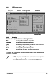
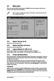
...or left arrow key on the keyboard until the desired item is highlighted. • The BIOS setup screens shown in .] Primary IDE Master Primary IDE Slave SATA1 SATA2 SATA3 SATA4 :[Not...BIOS SETUP UTILITY Power Boot Tools Exit General help System Time [19:34:30] System Date [Wed 08/27/2008] Legacy Diskette A [1.44M, 3.5 in this chapter are for reference purposes only, and may not exactly match what you see on your screen. • Visit the ASUS... website at www.asus.com to download the latest BIOS information. ASUS M3N78 SE 2-7 Select Screen Select Item +-
...or left arrow key on the keyboard until the desired item is highlighted. • The BIOS setup screens shown in .] Primary IDE Master Primary IDE Slave SATA1 SATA2 SATA3 SATA4 :[Not...BIOS SETUP UTILITY Power Boot Tools Exit General help System Time [19:34:30] System Date [Wed 08/27/2008] Legacy Diskette A [1.44M, 3.5 in this chapter are for reference purposes only, and may not exactly match what you see on your screen. • Visit the ASUS... website at www.asus.com to download the latest BIOS information. ASUS M3N78 SE 2-7 Select Screen Select Item +-
User Manual
Page 45
...Not Detected] :[Not Detected] Storage Configuration System Information Use [ENTER], [TAB] or [SHIFT-TAB] to display the IDE device information. The BIOS automatically detects the values opposite the dimmed items (Device, Vendor, Size, LBA Mode, Block Mode, PIO Mode, Async DMA, Ultra DMA, and...a field. Select [CDROM] if you an overview of the basic system information. Configuration options: [Not Installed] [Auto] [CDROM] [ARMD] ASUS M3N78 SE 2-9 Type [Auto] Selects the type of IDE devices. Use [+] or [-] to navigate through them. Change Field Tab Select Field F1 General Help...
...Not Detected] :[Not Detected] Storage Configuration System Information Use [ENTER], [TAB] or [SHIFT-TAB] to display the IDE device information. The BIOS automatically detects the values opposite the dimmed items (Device, Vendor, Size, LBA Mode, Block Mode, PIO Mode, Async DMA, Ultra DMA, and...a field. Select [CDROM] if you an overview of the basic system information. Configuration options: [Not Installed] [Auto] [CDROM] [ARMD] ASUS M3N78 SE 2-9 Type [Auto] Selects the type of IDE devices. Use [+] or [-] to navigate through them. Change Field Tab Select Field F1 General Help...
User Manual
Page 53
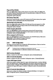
... to [Yes] and if you to enable or disable support for the PCI device latency timer register. Plug and Play O/S [No] When set to [No], BIOS configures all the devices in the system so that an ISA graphics device is disabled. Configuration options: [Yes] [No] Palette Snooping [Disabled] When set to... the latter can function correctly. Configuration options: [32] [64] [96] [128] [160] [192] [224] [248] Allocate IRQ to PCI VGA [Yes] When set to [No], BIOS does not assign an IRQ to display the configuration options. Configuration options: [FullSpeed] [HiSpeed] ASUS M3N78 SE 2-17
... to [Yes] and if you to enable or disable support for the PCI device latency timer register. Plug and Play O/S [No] When set to [No], BIOS configures all the devices in the system so that an ISA graphics device is disabled. Configuration options: [Yes] [No] Palette Snooping [Disabled] When set to... the latter can function correctly. Configuration options: [32] [64] [96] [128] [160] [192] [224] [248] Allocate IRQ to PCI VGA [Yes] When set to [No], BIOS does not assign an IRQ to display the configuration options. Configuration options: [FullSpeed] [HiSpeed] ASUS M3N78 SE 2-17
User Manual
Page 57
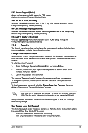
... Supervisor Password item on how to [Enabled], this item shows Installed. View Only allows access but does not allow you to run Setup during POST. ASUS M3N78 SE 2-21 Select the Change Supervisor Password item and press . 2. User Access Level [Full Access] This item allows you to select the access restriction to the... Capture [Disabled] When set or change other items appear to allow change to enable or disable support for 'F1' If Error [Enabled] When set your BIOS password, you can clear it by erasing the CMOS Real Time Clock (RTC) RAM.
... Supervisor Password item on how to [Enabled], this item shows Installed. View Only allows access but does not allow you to run Setup during POST. ASUS M3N78 SE 2-21 Select the Change Supervisor Password item and press . 2. User Access Level [Full Access] This item allows you to select the access restriction to the... Capture [Disabled] When set or change other items appear to allow change to enable or disable support for 'F1' If Error [Enabled] When set your BIOS password, you can clear it by erasing the CMOS Real Time Clock (RTC) RAM.
User Manual
Page 59
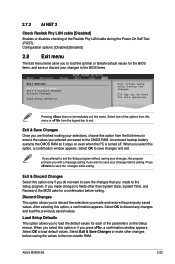
...press , a confirmation window appears. Select Exit & Save Changes or make other than System Date, System Time, and Password, the BIOS asks for the BIOS items, and save your changes before exiting. Pressing does not immediately exit this option or if you select this menu. When you ...;Test (POST). If you attempt to exit the Setup program without saving your changes to exit. ASUS M3N78 SE 2-23 Exit & Discard Changes Select this option from the legend bar to the BIOS items. Exit Options Exit & Save Changes Exit & Discard Changes Discard Changes Load Setup Defaults Exit...
...press , a confirmation window appears. Select Exit & Save Changes or make other than System Date, System Time, and Password, the BIOS asks for the BIOS items, and save your changes before exiting. Pressing does not immediately exit this option or if you select this menu. When you ...;Test (POST). If you attempt to exit the Setup program without saving your changes to exit. ASUS M3N78 SE 2-23 Exit & Discard Changes Select this option from the legend bar to the BIOS items. Exit Options Exit & Save Changes Exit & Discard Changes Discard Changes Load Setup Defaults Exit...


