
User Manual
Page 31
All rights reserved. done Write to file...... Version 1.19(ASUS V2.07(03.11.24BB)) Copyright (C) 2002 American Megatrends, Inc. exe 2 DOS afudos /o[filename filename A:\>afudos /oOLDBIOS1.rom 3. 按下 afudos /oOLDBIOS1.rom AMI Firmware Update Utility - Reading flash ..... ok A:\> 當 BIOS DOS 31 BIOS 2.1 使用 AFUDOS BIOS AFUDOS DOS BIOS BIOS 程式。AFUDOS BIOS BIOS BIOS 程式 BIOS 程式。 1.2MB BIOS 1 AFUDOS 程式(afudos.
All rights reserved. done Write to file...... Version 1.19(ASUS V2.07(03.11.24BB)) Copyright (C) 2002 American Megatrends, Inc. exe 2 DOS afudos /o[filename filename A:\>afudos /oOLDBIOS1.rom 3. 按下 afudos /oOLDBIOS1.rom AMI Firmware Update Utility - Reading flash ..... ok A:\> 當 BIOS DOS 31 BIOS 2.1 使用 AFUDOS BIOS AFUDOS DOS BIOS BIOS 程式。AFUDOS BIOS BIOS BIOS 程式 BIOS 程式。 1.2MB BIOS 1 AFUDOS 程式(afudos.

User Manual
Page 32
... BIOS 程式。 1 tw.asus.com BIOS 片中。 BIOS BIOS 2. 將 AFUDOS.EXE BIOS 3 DOS afudos /i[filename filename BIOS 程式。 A:\>afudos /iP5B-VM DO.ROM 4. Erasing flash ...... Do not turn off power during flash BIOS Reading file ....... Erasing flash ...... All rights reserved. done Verifying flash .... done Advance Check ...... done Advance Check ...... done BIOS 5. 當 BIOS...
... BIOS 程式。 1 tw.asus.com BIOS 片中。 BIOS BIOS 2. 將 AFUDOS.EXE BIOS 3 DOS afudos /i[filename filename BIOS 程式。 A:\>afudos /iP5B-VM DO.ROM 4. Erasing flash ...... Do not turn off power during flash BIOS Reading file ....... Erasing flash ...... All rights reserved. done Verifying flash .... done Advance Check ...... done Advance Check ...... done BIOS 5. 當 BIOS...

User Manual
Page 33
... Flash 程式(AWDFLASH.EXE BIOS AwardBIOS Flash BIOS 程式。 1 http://tw.asus.com BIOS M2N-VM HDMI.bin FAT 32/16 格式的 USB BIOS 2 CD/DVD AwardBIOS Flash BIOS 3 DOS 4. 當 A BIOS 檔案與 AwardBIOS Flash 5 A awdflash 並按下 鍵。 AwardBIOS Flash Utility for ASUS V1.14 (C) Phoenix Technologies Ltd...
... Flash 程式(AWDFLASH.EXE BIOS AwardBIOS Flash BIOS 程式。 1 http://tw.asus.com BIOS M2N-VM HDMI.bin FAT 32/16 格式的 USB BIOS 2 CD/DVD AwardBIOS Flash BIOS 3 DOS 4. 當 A BIOS 檔案與 AwardBIOS Flash 5 A awdflash 並按下 鍵。 AwardBIOS Flash Utility for ASUS V1.14 (C) Phoenix Technologies Ltd...

User Manual
Page 34
... Pm49FL004T LPC/FWH File Name to Program: M2A-VM HDMI.bin Flashing Complete Press to Program: M2A-VM HDMI.bin Programming Flash Memory - PMC Pm49FL004T LPC/FWH File Name to Continue Write OK F1 Reset No Update Write Fail 34 BIOS 7 BIOS N BIOS 8 BIOS BIOS AwardBIOS Flash Utility for ASUS V1.14 (C) Phoenix Technologies Ltd. All Rights Reserved...
... Pm49FL004T LPC/FWH File Name to Program: M2A-VM HDMI.bin Flashing Complete Press to Program: M2A-VM HDMI.bin Programming Flash Memory - PMC Pm49FL004T LPC/FWH File Name to Continue Write OK F1 Reset No Update Write Fail 34 BIOS 7 BIOS N BIOS 8 BIOS BIOS AwardBIOS Flash Utility for ASUS V1.14 (C) Phoenix Technologies Ltd. All Rights Reserved...

User Manual
Page 4
Contents 1.10.2 Internal connectors 1-28 Chapter 2 BIOS setup 2.1 Managing and updating your BIOS 2-2 2.1.1 Creating a bootable floppy disk 2-3 2.1.2 ASUS EZ Flash 2 utility 2-4 2.1.3 AFUDOS utility 2-5 2.1.4 ASUS Update utility 2-7 2.2 BIOS setup program 2-10 2.2.1 BIOS menu screen 2-11 2.2.2 Menu bar 2-11 2.2.3 Navigation keys 2-11 2.2.4 Menu items 2-12 2.2.5 Sub-menu items 2-12 2.2.6 Configuration fields 2-12 2.2.7 Pop-up window 2-12 2.2.8 Scroll bar 2-...
Contents 1.10.2 Internal connectors 1-28 Chapter 2 BIOS setup 2.1 Managing and updating your BIOS 2-2 2.1.1 Creating a bootable floppy disk 2-3 2.1.2 ASUS EZ Flash 2 utility 2-4 2.1.3 AFUDOS utility 2-5 2.1.4 ASUS Update utility 2-7 2.2 BIOS setup program 2-10 2.2.1 BIOS menu screen 2-11 2.2.2 Menu bar 2-11 2.2.3 Navigation keys 2-11 2.2.4 Menu items 2-12 2.2.5 Sub-menu items 2-12 2.2.6 Configuration fields 2-12 2.2.7 Pop-up window 2-12 2.2.8 Scroll bar 2-...

User Manual
Page 8
...configuring the motherboard. Where to find more information Refer to change system settings through the BIOS Setup menus. ASUS websites The ASUS website provides updated information on the motherboard. • Chapter 2: BIOS setup This chapter tells how to the following parts: • Chapter 1: Product ... your dealer. It includes description of the support DVD that may have to the ASUS contact information. 2. Refer to perform when installing system components. Detailed descriptions of the BIOS parameters are not part of the motherboard and the new technology it supports.
...configuring the motherboard. Where to find more information Refer to change system settings through the BIOS Setup menus. ASUS websites The ASUS website provides updated information on the motherboard. • Chapter 2: BIOS setup This chapter tells how to the following parts: • Chapter 1: Product ... your dealer. It includes description of the support DVD that may have to the ASUS contact information. 2. Refer to perform when installing system components. Detailed descriptions of the BIOS parameters are not part of the motherboard and the new technology it supports.
User Manual
Page 12
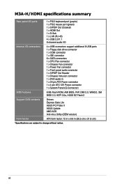
M3A-H/HDMI specifications summary Rear panel I/O ports 1 x PS/2 keyboard port (purple) 1 x PS/2 mouse port (green) 1 x S/PDIF Out (Coaxial) 1 x HDMI Out 1 x D-Sub 1 x LAN (RJ-45) 4 x USB 2.0/1.1 8-channel audio I/O Internal I/O connectors 4 x USB connectors support additional 8 USB ports 1 x Floppy...pin ATX 12V Power connector 1 x System Panel (Q-Connector) BIOS features 8 Mb Flash ROM, AMI BIOS, PnP, DMI 2.0, WfM2.0, SM BIOS 2.3, ACPI 2.0a, ASUS EZ Flash 2 Support DVD contents Drivers Express Gate Lite ASUS PC Probe II ASUS Update AMD AOD Anti-virus Utility (OEM version) Form factor...
M3A-H/HDMI specifications summary Rear panel I/O ports 1 x PS/2 keyboard port (purple) 1 x PS/2 mouse port (green) 1 x S/PDIF Out (Coaxial) 1 x HDMI Out 1 x D-Sub 1 x LAN (RJ-45) 4 x USB 2.0/1.1 8-channel audio I/O Internal I/O connectors 4 x USB connectors support additional 8 USB ports 1 x Floppy...pin ATX 12V Power connector 1 x System Panel (Q-Connector) BIOS features 8 Mb Flash ROM, AMI BIOS, PnP, DMI 2.0, WfM2.0, SM BIOS 2.3, ACPI 2.0a, ASUS EZ Flash 2 Support DVD contents Drivers Express Gate Lite ASUS PC Probe II ASUS Update AMD AOD Anti-virus Utility (OEM version) Form factor...

User Manual
Page 18
... DOES NOT support PATA IDE HDDs. You can be stored in the BIOS to conveniently store or load multiple BIOS settings. See page 1-36 for future BIOS and Express Gate Lite software updates. Visit www.asus.com for details. ASUS EZ DIY ASUS EZ DIY feature collection provides you easy ways to install computer components, update...
... DOES NOT support PATA IDE HDDs. You can be stored in the BIOS to conveniently store or load multiple BIOS settings. See page 1-36 for future BIOS and Express Gate Lite software updates. Visit www.asus.com for details. ASUS EZ DIY ASUS EZ DIY feature collection provides you easy ways to install computer components, update...

User Manual
Page 19
... the hassle of the computer. feature of the motherboard BIOS allows automatic re-setting to the BIOS default settings in 0.02V steps to overclocking, C.P.R. Simply shut down and reboot the system, and the BIOS automatically restores the CPU default setting for details. ASUS M3A-H/HDMI 1-7 See pages 2-4 and 2-39 for each parameter. eliminates the need to...
... the hassle of the computer. feature of the motherboard BIOS allows automatic re-setting to the BIOS default settings in 0.02V steps to overclocking, C.P.R. Simply shut down and reboot the system, and the BIOS automatically restores the CPU default setting for details. ASUS M3A-H/HDMI 1-7 See pages 2-4 and 2-39 for each parameter. eliminates the need to...

User Manual
Page 21
ASUS M3A-H/HDMI 1-9 1.5 1.5.1 Motherboard overview Motherboard layout 21.8cm (8.6in) KBMS USB34 KBPWR USBPW1-4 CPU_FAN SPDIF_O1 DDR DIMM_A1 (64bit, 240-pin module) DDR DIMM_B1 (64bit, 240-pin module) ..., 240-pin module) 30.5cm (12.0in) SOCKET AM2 VGA_HDMI LAN1_USB12 PRI_IDE AUDIO Lithium Cell CMOS Power ATX12V Attansic L1 CHA_FAN1 AMD 780G COM1 PCIEX1_1 M3A-H/HDMI ® PCIEX16_1 EATXPWR Super I/O PCIEX1_2 ICS PCI1 AMD SB700 PWR_FAN SB_PWR PCI2 ALC1200 AAFP SPDIF_OUT CD FLOPPY PCI3 CLRTC SATA1 SATA2 USB1112 USBPW9-12 SATA3...
ASUS M3A-H/HDMI 1-9 1.5 1.5.1 Motherboard overview Motherboard layout 21.8cm (8.6in) KBMS USB34 KBPWR USBPW1-4 CPU_FAN SPDIF_O1 DDR DIMM_A1 (64bit, 240-pin module) DDR DIMM_B1 (64bit, 240-pin module) ..., 240-pin module) 30.5cm (12.0in) SOCKET AM2 VGA_HDMI LAN1_USB12 PRI_IDE AUDIO Lithium Cell CMOS Power ATX12V Attansic L1 CHA_FAN1 AMD 780G COM1 PCIEX1_1 M3A-H/HDMI ® PCIEX16_1 EATXPWR Super I/O PCIEX1_2 ICS PCI1 AMD SB700 PWR_FAN SB_PWR PCI2 ALC1200 AAFP SPDIF_OUT CD FLOPPY PCI3 CLRTC SATA1 SATA2 USB1112 USBPW9-12 SATA3...
User Manual
Page 33
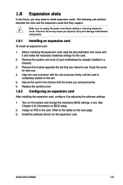
.... Install the software drivers for information on the slot. 5. Refer to install expansion cards. ASUS M3A-H/HDMI 1-21 Failure to do so may cause you may need to the tables on the system and change the necessary BIOS settings, if any. Keep the screw for the card. 2. Remove the system unit cover ...(if your motherboard is completely seated on BIOS setup. 2. Make sure to the card. Assign an IRQ to unplug the ...
.... Install the software drivers for information on the slot. 5. Refer to install expansion cards. ASUS M3A-H/HDMI 1-21 Failure to do so may cause you may need to the tables on the system and change the necessary BIOS settings, if any. Keep the screw for the card. 2. Remove the system unit cover ...(if your motherboard is completely seated on BIOS setup. 2. Make sure to the card. Assign an IRQ to unplug the ...

User Manual
Page 36
... the power cord. 2. Move the jumper cap from pins 1-2 (default) to overclocking, use the C.P.R. (CPU Parameter Recall) feature. M3A-H/HDMI ® CLRTC 12 23 Normal Clear RTC (Default) M3A-H/HDMI Clear RTC RAM • You do not help, remove the onboard battery and move the cap back to overclocking. Shut down... the key during the boot process and enter BIOS setup to clear the CMOS RTC RAM data. Keep the cap...
... the power cord. 2. Move the jumper cap from pins 1-2 (default) to overclocking, use the C.P.R. (CPU Parameter Recall) feature. M3A-H/HDMI ® CLRTC 12 23 Normal Clear RTC (Default) M3A-H/HDMI Clear RTC RAM • You do not help, remove the onboard battery and move the cap back to overclocking. Shut down... the key during the boot process and enter BIOS setup to clear the CMOS RTC RAM data. Keep the cap...
User Manual
Page 37
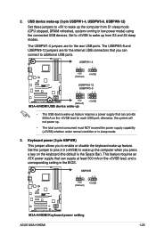
... that can provide 500mA on the +5VSB lead, and a corresponding setting in the BIOS. KBPWR 12 23 +5V (Default) +5VSB M3A-H/HDMI ® M3A-H/HDMI Keyboard power setting ASUS M3A-H/HDMI 1-25 USBPW1-4 12 23 +5V (Default) +5VSB M3A-H/HDMI ® USBPW9-12 USBPW5-8 12 23 +5V (Default) M3A-H/HDMI USB device wake-up +5VSB • The USB device wake-up . •...
... that can provide 500mA on the +5VSB lead, and a corresponding setting in the BIOS. KBPWR 12 23 +5V (Default) +5VSB M3A-H/HDMI ® M3A-H/HDMI Keyboard power setting ASUS M3A-H/HDMI 1-25 USBPW1-4 12 23 +5V (Default) +5VSB M3A-H/HDMI ® USBPW9-12 USBPW5-8 12 23 +5V (Default) M3A-H/HDMI USB device wake-up +5VSB • The USB device wake-up . •...

User Manual
Page 42
...with 133 MB/s (Ultra DMA133). 4. GND RSATA_RXN4 RSATA_TXP4 GND RSATA_TXN4 RSATA_TXP4 GND GND RSATA_RXN3 RSATA_TXP3 GND RSATA_TXN3 RSATA_TXP3 GND M3A-H/HDMI ® GND RSATA_RXN2 RSATA_TXP2 GND RSATA_TXN2 RSATA_TXP2 GND SATA3 SATA2 GND RSATA_RXN5 RSATA_TXP5 GND RSATA_TXN5 RSATA_TXP5 GND SATA4 SATA5 GND ...RSATA_TXN6 RSATA_TXP6 GND GND RSATA_RXN1 RSATA_TXP1 GND RSATA_TXN1 RSATA_TXP1 GND M3A-H/HDMI SATA connectors SATA1 SATA6 Important note on how to configure RAID 0, RAID 1 and RAID 10, refer to the RAID manual in the BIOS to SATA device. right angle side 1-30 Chapter 1:...
...with 133 MB/s (Ultra DMA133). 4. GND RSATA_RXN4 RSATA_TXP4 GND RSATA_TXN4 RSATA_TXP4 GND GND RSATA_RXN3 RSATA_TXP3 GND RSATA_TXN3 RSATA_TXP3 GND M3A-H/HDMI ® GND RSATA_RXN2 RSATA_TXP2 GND RSATA_TXN2 RSATA_TXP2 GND SATA3 SATA2 GND RSATA_RXN5 RSATA_TXP5 GND RSATA_TXN5 RSATA_TXP5 GND SATA4 SATA5 GND ...RSATA_TXN6 RSATA_TXP6 GND GND RSATA_RXN1 RSATA_TXP1 GND RSATA_TXN1 RSATA_TXP1 GND M3A-H/HDMI SATA connectors SATA1 SATA6 Important note on how to configure RAID 0, RAID 1 and RAID 10, refer to the RAID manual in the BIOS to SATA device. right angle side 1-30 Chapter 1:...
User Manual
Page 45
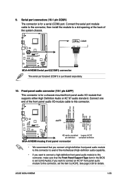
...`97 front panel audio module to this connector, set to this connector, make sure that supports either High Definition Audio or AC`97 audio standard. ASUS M3A-H/HDMI 1-33 Front panel audio connector (10-1 pin AAFP) This connector is for a chassis-mounted front panel audio I /O module cable to [HD ...front panel audio module to a slot opening at the back of the front panel audio I /O module that the Front Panel Support Type item in the BIOS is purchased separately. 10. 9. Serial port connectors (10-1 pin COM1) The connector is for a serial (COM) port. See page 2-28 for details...
...`97 front panel audio module to this connector, set to this connector, make sure that supports either High Definition Audio or AC`97 audio standard. ASUS M3A-H/HDMI 1-33 Front panel audio connector (10-1 pin AAFP) This connector is for a chassis-mounted front panel audio I /O module cable to [HD ...front panel audio module to a slot opening at the back of the front panel audio I /O module that the Front Panel Support Type item in the BIOS is purchased separately. 10. 9. Serial port connectors (10-1 pin COM1) The connector is for a serial (COM) port. See page 2-28 for details...
User Manual
Page 47
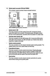
...connector (20-8 pin PANEL) This connector supports several chassis-mounted functions. PLED SPEAKER PLED+ PLED+5V Ground Ground Speaker M3A-H/HDMI ® PANEL PIN 1 IDE_LED+ IDE_LED- Connect the HDD Activity LED cable to the HDD. • System warning...8226; Reset button This 2-pin connector is for the HDD Activity LED. ASUS M3A-H/HDMI 1-35 PWR Ground Reset Ground IDE_LED PWRSW RESET * Requires an ATX power supply M3A-H/HDMI System panel connector • System power LED This 2-pin connector is ...2-pin connector is in SLEEP or SOFT-OFF mode depending on the BIOS settings.
...connector (20-8 pin PANEL) This connector supports several chassis-mounted functions. PLED SPEAKER PLED+ PLED+5V Ground Ground Speaker M3A-H/HDMI ® PANEL PIN 1 IDE_LED+ IDE_LED- Connect the HDD Activity LED cable to the HDD. • System warning...8226; Reset button This 2-pin connector is for the HDD Activity LED. ASUS M3A-H/HDMI 1-35 PWR Ground Reset Ground IDE_LED PWRSW RESET * Requires an ATX power supply M3A-H/HDMI System panel connector • System power LED This 2-pin connector is ...2-pin connector is in SLEEP or SOFT-OFF mode depending on the BIOS settings.

User Manual
Page 49
This chapter tells how to change the system settings through the BIOS Setup menus. Chapter 2 2 BIOS setup Detailed descriptions of the BIOS parameters are also provided.
This chapter tells how to change the system settings through the BIOS Setup menus. Chapter 2 2 BIOS setup Detailed descriptions of the BIOS parameters are also provided.

User Manual
Page 50
... case you to manage and update the motherboard Basic Input/Output System (BIOS) setup. 1. ASUS AFUDOS (Updates the BIOS in DOS mode using the ASUS Update or AFUDOS utilities. 2-2 Chapter 2: BIOS setup Copy the original motherboard BIOS using a bootable floppy disk.) 3. ASUS Update (Updates the BIOS in Windows® environment.) Refer to the corresponding sections for details on...
... case you to manage and update the motherboard Basic Input/Output System (BIOS) setup. 1. ASUS AFUDOS (Updates the BIOS in DOS mode using the ASUS Update or AFUDOS utilities. 2-2 Chapter 2: BIOS setup Copy the original motherboard BIOS using a bootable floppy disk.) 3. ASUS Update (Updates the BIOS in Windows® environment.) Refer to the corresponding sections for details on...
User Manual
Page 51
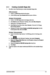
...disk drive. Select the Create an MS-DOS startup disk check box. Do either one of the following to the bootable floppy disk. e. ASUS M3A-H/HDMI 2-3 Windows® XP environment a. Windows® Vista environment a. Click Start. 2. Select the 3 1/2 Floppy Drive icon. Click File ...from the Windows® desktop, then select My Computer. A Format 3 1/2 Floppy Disk window appears. Copy the original or the latest motherboard BIOS file to create a bootable floppy disk. Click Start from the menu, then select Format. DOS environment a. Insert a 1.44MB floppy disk into...
...disk drive. Select the Create an MS-DOS startup disk check box. Do either one of the following to the bootable floppy disk. e. ASUS M3A-H/HDMI 2-3 Windows® XP environment a. Windows® Vista environment a. Click Start. 2. Select the 3 1/2 Floppy Drive icon. Click File ...from the Windows® desktop, then select My Computer. A Format 3 1/2 Floppy Disk window appears. Copy the original or the latest motherboard BIOS file to create a bootable floppy disk. Click Start from the menu, then select Format. DOS environment a. Insert a 1.44MB floppy disk into...

User Manual
Page 52
... from a floppy disk and using EZ Flash 2: 1. 2.1.2 ASUS EZ Flash 2 utility The ASUS EZ Flash 2 feature allows you to update the BIOS without having to download the latest BIOS file for the motherboard. 2. ASUSTek EZ Flash 2 BIOS ROM Utility V3.06 FLASH TYPE: SST 25LF080 Current ROM BOARD: M3A-H/HDMI VER: 0109 DATE: 02/14/08 Update...
... from a floppy disk and using EZ Flash 2: 1. 2.1.2 ASUS EZ Flash 2 utility The ASUS EZ Flash 2 feature allows you to update the BIOS without having to download the latest BIOS file for the motherboard. 2. ASUSTek EZ Flash 2 BIOS ROM Utility V3.06 FLASH TYPE: SST 25LF080 Current ROM BOARD: M3A-H/HDMI VER: 0109 DATE: 02/14/08 Update...


