
User Manual
Page 1
M2N68 PLUS Motherboard
M2N68 PLUS Motherboard

User Manual
Page 3
Contents Notices...vi Safety information vii About this guide vii M2N68 PLUS specifications summary ix Chapter 1: Product introduction 1.1 Welcome 1-1 1.2 Package contents 1-1 1.3 Special features 1-1 1.3.1 Product highlights 1-1 1.3.2 Innovative ASUS features 1-3 1.4 Before you proceed 1-4 1.5 Motherboard overview 1-5 1.5.1 Placement direction 1-5 1.5.2 Screw holes 1-5 1.5.3 Motherboard layout 1-6 1.5.4 Layout contents 1-7 1.6 Central Processing Unit (CPU 1-7 1.6.1 Installing the CPU 1-7 1.6.2 Installing the heatsink and fan 1-9 1.7 System memory 1-10...
Contents Notices...vi Safety information vii About this guide vii M2N68 PLUS specifications summary ix Chapter 1: Product introduction 1.1 Welcome 1-1 1.2 Package contents 1-1 1.3 Special features 1-1 1.3.1 Product highlights 1-1 1.3.2 Innovative ASUS features 1-3 1.4 Before you proceed 1-4 1.5 Motherboard overview 1-5 1.5.1 Placement direction 1-5 1.5.2 Screw holes 1-5 1.5.3 Motherboard layout 1-6 1.5.4 Layout contents 1-7 1.6 Central Processing Unit (CPU 1-7 1.6.1 Installing the CPU 1-7 1.6.2 Installing the heatsink and fan 1-9 1.7 System memory 1-10...
User Manual
Page 11
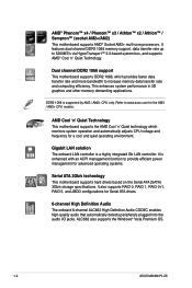
... hardware devices on it another standout in the long line of ASUS quality motherboards! Before you for the following items. Motherboard Cables Accessories Application DVD Documentation ASUS M2N68 PLUS motherboard 1 x Serial ATA cable 1 x Ultra DMA 133/100/66 cable 1 x I/O shield ASUS motherboard support DVD User guide If any of new features and latest technologies, making it , check the items...
... hardware devices on it another standout in the long line of ASUS quality motherboards! Before you for the following items. Motherboard Cables Accessories Application DVD Documentation ASUS M2N68 PLUS motherboard 1 x Serial ATA cable 1 x Ultra DMA 133/100/66 cable 1 x I/O shield ASUS motherboard support DVD User guide If any of new features and latest technologies, making it , check the items...
User Manual
Page 12
...'n' Quiet Technology This motherboard supports the AMD Cool 'n' Quiet technology which provides faster data transfer rate and more bandwidth to provide efficient power management for a cool and quiet operating environment. ALC662 also supports the Windows® Vista Premium OS. 1-2 ASUS M2N68 PLUS It also supports RAID... 0, RAID 1, RAID 0+1, RAID 5, and JBOD configurations for the AM3 / AM2+ CPU models. It features dual-channel DDR2 1066 memory support, data transfer rate up to www.asus.com for Serial ATA drives. ...
...'n' Quiet Technology This motherboard supports the AMD Cool 'n' Quiet technology which provides faster data transfer rate and more bandwidth to provide efficient power management for a cool and quiet operating environment. ALC662 also supports the Windows® Vista Premium OS. 1-2 ASUS M2N68 PLUS It also supports RAID... 0, RAID 1, RAID 0+1, RAID 5, and JBOD configurations for the AM3 / AM2+ CPU models. It features dual-channel DDR2 1066 memory support, data transfer rate up to www.asus.com for Serial ATA drives. ...
User Manual
Page 14
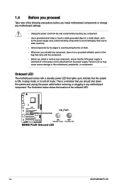
...Standby Power Powered Off M2N68 PLUS Onboard LED 1-4 ASUS M2N68 PLUS Failure to do so may cause severe damage to indicate that the system is ON, in sleep mode, or in soft-off or the power cord is switched off mode. Onboard LED The motherboard comes with the component.... you uninstall any component, place it on a grounded antistatic pad or in any motherboard component. The illustration below shows the location of the following precautions before you install motherboard components or change any motherboard settings. • Unplug the power cord from the power supply. This is a...
...Standby Power Powered Off M2N68 PLUS Onboard LED 1-4 ASUS M2N68 PLUS Failure to do so may cause severe damage to indicate that the system is ON, in sleep mode, or in soft-off or the power cord is switched off mode. Onboard LED The motherboard comes with the component.... you uninstall any component, place it on a grounded antistatic pad or in any motherboard component. The illustration below shows the location of the following precautions before you install motherboard components or change any motherboard settings. • Unplug the power cord from the power supply. This is a...
User Manual
Page 16
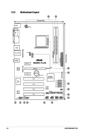
1.5.3 Motherboard layout 1 2 20.3cm(8.0in) KBMS ATX12V COM LPT CPU Socket DDR2-1066 DDR2 DIMM_A1 (64bit, 240-pin module) DDR2 DIMM_B1 (64bit, 240-pin module) EATXPWR 30.5cm(12.0in) 4PHASE POWER 5000HRS VRM USB34 LAN1_USB12 CPU_FAN AUDIO PCIEX1_1 M2N68 PLUS 1000M LAN Realtek PCIEX16 3 8211CL SATA RAID Lithium Cell 4 PCIEX1_2 CMOS Power PCI1 SB_PWR NVIDIA® MCP68 SE Super I/O SATA4 PCI2 SATA3 5 SATA2 ALC 662 AAFP PCI3 CD SPDIF_OUT PCI4 8Mb BIOS SATA1 6 CLRTC PRI_IDE SPEAKER 7 USB56 USB78 USB910 F_PANEL 8 14 13 12 11 10 9 1-6 ASUS M2N68 PLUS
1.5.3 Motherboard layout 1 2 20.3cm(8.0in) KBMS ATX12V COM LPT CPU Socket DDR2-1066 DDR2 DIMM_A1 (64bit, 240-pin module) DDR2 DIMM_B1 (64bit, 240-pin module) EATXPWR 30.5cm(12.0in) 4PHASE POWER 5000HRS VRM USB34 LAN1_USB12 CPU_FAN AUDIO PCIEX1_1 M2N68 PLUS 1000M LAN Realtek PCIEX16 3 8211CL SATA RAID Lithium Cell 4 PCIEX1_2 CMOS Power PCI1 SB_PWR NVIDIA® MCP68 SE Super I/O SATA4 PCI2 SATA3 5 SATA2 ALC 662 AAFP PCI3 CD SPDIF_OUT PCI4 8Mb BIOS SATA1 6 CLRTC PRI_IDE SPEAKER 7 USB56 USB78 USB910 F_PANEL 8 14 13 12 11 10 9 1-6 ASUS M2N68 PLUS
User Manual
Page 18
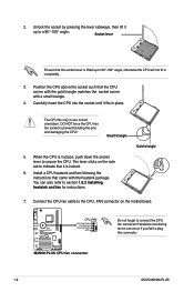
... also refer to indicate that the CPU corner with the gold triangle matches the socket corner with the heatsink package. The lever clicks on the motherboard. 2. Unlock the socket by pressing the lever sideways, then lift it fits in completely. 3. The CPU fits only in place, push down the...to prevent bending the pins and damaging the CPU! DO NOT force the CPU into the socket until it up to plug this connector. 1-8 ASUS M2N68 PLUS Do not forget to secure the CPU. Connect the CPU fan cable to the CPU_FAN connector on the side tab to section 1.6.2 Installing heatsink ...
... also refer to indicate that the CPU corner with the gold triangle matches the socket corner with the heatsink package. The lever clicks on the motherboard. 2. Unlock the socket by pressing the lever sideways, then lift it fits in completely. 3. The CPU fits only in place, push down the...to prevent bending the pins and damaging the CPU! DO NOT force the CPU into the socket until it up to plug this connector. 1-8 ASUS M2N68 PLUS Do not forget to secure the CPU. Connect the CPU fan cable to the CPU_FAN connector on the side tab to section 1.6.2 Installing heatsink ...
User Manual
Page 20
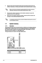
... DIMM. Make sure that the retention bracket is in place. 4. 3. Do not forget to prevent installation on the motherboard labeled CPU_FAN. A DDR2 module has the same physical dimensions as a DDR DIMM but has a 240-pin footprint compared... to plug this connector. 1.7 System memory 1.7.1 Overview The motherboard comes with two Double Data Rate 2 (DDR2) Dual Inline Memory Modules (DIMM) sockets. Hardware monitoring errors can occur ...the DDR2 DIMM sockets: Channel Channel A Channel B 1-10 Sockets DIMM_A1 DIMM_B1 ASUS M2N68 PLUS
... DIMM. Make sure that the retention bracket is in place. 4. 3. Do not forget to prevent installation on the motherboard labeled CPU_FAN. A DDR2 module has the same physical dimensions as a DDR DIMM but has a 240-pin footprint compared... to plug this connector. 1.7 System memory 1.7.1 Overview The motherboard comes with two Double Data Rate 2 (DDR2) Dual Inline Memory Modules (DIMM) sockets. Hardware monitoring errors can occur ...the DDR2 DIMM sockets: Channel Channel A Channel B 1-10 Sockets DIMM_A1 DIMM_B1 ASUS M2N68 PLUS
User Manual
Page 21
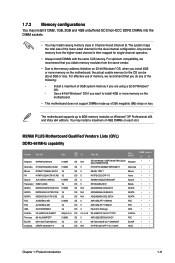
...Use a 64-bit Windows® OS if you install 4GB or more memory on the motherboard. • This motherboard does not support DIMMs made up to install 4GB or more memory on the motherboard, the actual usable memory for single-channel operation. • Always install DIMMs with the ... that you are using a 32-bit Windows® OS. - Size SS/ DS CL Chip No. M2N68 PLUS Motherboard Qualified Vendors Lists (QVL) DDR2-667MHz capability Vendor Part No. The motherboard supports up of 3GB system memory if you obtain memory modules from the higher-sized channel is then mapped ...
...Use a 64-bit Windows® OS if you install 4GB or more memory on the motherboard. • This motherboard does not support DIMMs made up to install 4GB or more memory on the motherboard, the actual usable memory for single-channel operation. • Always install DIMMs with the ... that you are using a 32-bit Windows® OS. - Size SS/ DS CL Chip No. M2N68 PLUS Motherboard Qualified Vendors Lists (QVL) DDR2-667MHz capability Vendor Part No. The motherboard supports up of 3GB system memory if you obtain memory modules from the higher-sized channel is then mapped ...
User Manual
Page 24
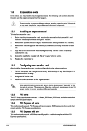
...ASUS M2N68 PLUS Otherwise, conflicts will arise between the two PCI groups, making the system unstable and the card inoperable. 1.8.3 PCI slots The PCI slots support cards such as a LAN card, SCSI card, USB card, and other cards that comply with PCI specifications. 1.8.4 PCI Express x1 slots This motherboard...Install the software drivers for the card. 2. 1.8 Expansion slots In the future, you may cause you physical injury and damage motherboard components. 1.8.1 Installing an expansion card To install an expansion card: 1. Replace the system cover. 1.8.2 Configuring an expansion card ...
...ASUS M2N68 PLUS Otherwise, conflicts will arise between the two PCI groups, making the system unstable and the card inoperable. 1.8.3 PCI slots The PCI slots support cards such as a LAN card, SCSI card, USB card, and other cards that comply with PCI specifications. 1.8.4 PCI Express x1 slots This motherboard...Install the software drivers for the card. 2. 1.8 Expansion slots In the future, you may cause you physical injury and damage motherboard components. 1.8.1 Installing an expansion card To install an expansion card: 1. Replace the system cover. 1.8.2 Configuring an expansion card ...
User Manual
Page 28
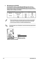
IDE connector (40-1 pin PRI_IDE) The onboard IDE connector is set as "Cable-Select", ensure that all other device jumpers have the same setting. 1-18 ASUS M2N68 PLUS There are three connectors on the Ultra DMA cable connector. Master Slave Master Slave Cable connector Black Black Gray Black or gray • Pin 20 ... modes to match the covered hole on each Ultra DMA 133/100/66 signal cable: blue, black, and gray. Connect the blue connector to the motherboard's IDE connector, then select one of device(s) - 3.
IDE connector (40-1 pin PRI_IDE) The onboard IDE connector is set as "Cable-Select", ensure that all other device jumpers have the same setting. 1-18 ASUS M2N68 PLUS There are three connectors on the Ultra DMA cable connector. Master Slave Master Slave Cable connector Black Black Gray Black or gray • Pin 20 ... modes to match the covered hole on each Ultra DMA 133/100/66 signal cable: blue, black, and gray. Connect the blue connector to the motherboard's IDE connector, then select one of device(s) - 3.
User Manual
Page 30
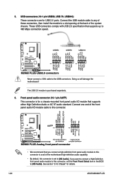
... that you want to connect a High Definition front panel audio module to this connector is purchased separately. 6. Connect one end of the motherboard high-definition audio capability. • By default, this connector, set to [HD Audio]. If you connect a high-definition front panel ...audio I /O module that supports up to [HD Audio]. Doing so will damage the motherboard! USB connectors (10-1 pin USB56, USB 78, USB910) These connectors are for details. 1-20 ASUS M2N68 PLUS These USB connectors comply with USB 2.0 specification that supports either High Definition Audio or ...
... that you want to connect a High Definition front panel audio module to this connector is purchased separately. 6. Connect one end of the motherboard high-definition audio capability. • By default, this connector, set to [HD Audio]. If you connect a high-definition front panel ...audio I /O module that supports up to [HD Audio]. Doing so will damage the motherboard! USB connectors (10-1 pin USB56, USB 78, USB910) These connectors are for details. 1-20 ASUS M2N68 PLUS These USB connectors comply with USB 2.0 specification that supports either High Definition Audio or ...
User Manual
Page 32
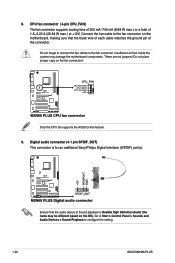
... to connect the fan cables to configure the setting. 1-22 ASUS M2N68 PLUS Do not place jumper caps on the OS). CPU fan connector...of Sound playback is for an additional Sony/Philips Digital Interface (S/PDIF) port(s). Only the CPU fan supports the ASUS Q-Fan feature. 9. Go to Start > Control Panel > Sounds and Audio Devices > Sound Playback to the... This connector is Realtek High Definition Audio (the name may damage the motherboard components. 8. Connect the fan cable to the fan connector on the motherboard, making sure that the audio device of 1 A~2.22 A (26.64 W...
... to connect the fan cables to configure the setting. 1-22 ASUS M2N68 PLUS Do not place jumper caps on the OS). CPU fan connector...of Sound playback is for an additional Sony/Philips Digital Interface (S/PDIF) port(s). Only the CPU fan supports the ASUS Q-Fan feature. 9. Go to Start > Control Panel > Sounds and Audio Devices > Sound Playback to the... This connector is Realtek High Definition Audio (the name may damage the motherboard components. 8. Connect the fan cable to the fan connector on the motherboard, making sure that the audio device of 1 A~2.22 A (26.64 W...
User Manual
Page 34
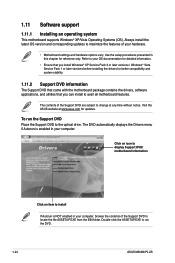
... drive. To run the DVD. 1-24 ASUS M2N68 PLUS Use the setup procedures presented in your computer, browse the contents of the Support DVD to change at www.asus.com for updates. Visit the ASUS website at any time without notice. Click an icon to display Support DVD/ motherboard information Click an item to install If...
... drive. To run the DVD. 1-24 ASUS M2N68 PLUS Use the setup procedures presented in your computer, browse the contents of the Support DVD to change at www.asus.com for updates. Visit the ASUS website at any time without notice. Click an icon to display Support DVD/ motherboard information Click an item to install If...
User Manual
Page 38
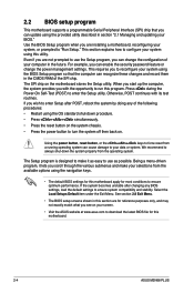
...are installing a motherboard, reconfiguring your screen. • Visit the ASUS website at www.asus.com to turn the system off then back on the motherboard stores the Setup utility. See section 2.8 Exit Menu. • The BIOS setup screens shown in this motherboard. 2-4 ASUS M2N68 PLUS If you are... options using the provided utility described in section "2.1 Managing and updating your data or system. 2.2 BIOS setup program This motherboard supports a programmable Serial Peripheral Interface (SPI) chip that the computer can recognize these changes and record them in the CMOS...
...are installing a motherboard, reconfiguring your screen. • Visit the ASUS website at www.asus.com to turn the system off then back on the motherboard stores the Setup utility. See section 2.8 Exit Menu. • The BIOS setup screens shown in this motherboard. 2-4 ASUS M2N68 PLUS If you are... options using the provided utility described in section "2.1 Managing and updating your data or system. 2.2 BIOS setup program This motherboard supports a programmable Serial Peripheral Interface (SPI) chip that the computer can recognize these changes and record them in the CMOS...
User Manual
Page 50
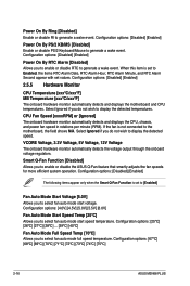
...[67ºC] [68ºC] [69ºC] [70ºC] [71ºC] [72ºC] [73ºC] [74ºC] [75ºC] 2-16 ASUS M2N68 PLUS Smart Q-Fan Function [Disabled] Allows you to Enabled, the items RTC Alarm Date, RTC Alarm Hour, RTC Alarm Minute, and RTC Alarm Second appear with...speeds for more efficient system operation. Configuration options: [Disabled] [Enabled] Power On By RTC Alarm [Disabled] Allows you do not wish to the motherboard, the field shows N/A. Select Ignored if you to enable or disable RTC to display the detected temperatures. Configuration options: [4.0V] [4.5V] [5.0V]...
...[67ºC] [68ºC] [69ºC] [70ºC] [71ºC] [72ºC] [73ºC] [74ºC] [75ºC] 2-16 ASUS M2N68 PLUS Smart Q-Fan Function [Disabled] Allows you to Enabled, the items RTC Alarm Date, RTC Alarm Hour, RTC Alarm Minute, and RTC Alarm Second appear with...speeds for more efficient system operation. Configuration options: [Disabled] [Enabled] Power On By RTC Alarm [Disabled] Allows you do not wish to the motherboard, the field shows N/A. Select Ignored if you to enable or disable RTC to display the detected temperatures. Configuration options: [4.0V] [4.5V] [5.0V]...


