
Motherboard Installation Guide
Page 3
Contents Notices...vi Safety information vii M2A-VM specifications summary x Chapter 1: Product introduction 1.1 Welcome 1-2 1.2 Package contents 1-2 1.3 Special features 1-2 1.3.1 Product highlights 1-2 1.3.2 Innovative ASUS features 1-4 1.4 Before you proceed 1-6 1.5 Motherboard overview 1-7 1.5.1 Motherboard layout 1-7 1.5.2 Placement direction 1-8 1.5.3 Screw holes 1-8 1.6 Central Processing Unit (CPU 1-9 1.6.1 Installing the CPU 1-9 1.6.2 ...PCI Express x16 slot 1-20 1.9 Jumpers 1-21 1.10 Connectors 1-23 1.10.1 Rear panel connectors 1-23 1.10.2 Internal connectors 1-25 iii
Contents Notices...vi Safety information vii M2A-VM specifications summary x Chapter 1: Product introduction 1.1 Welcome 1-2 1.2 Package contents 1-2 1.3 Special features 1-2 1.3.1 Product highlights 1-2 1.3.2 Innovative ASUS features 1-4 1.4 Before you proceed 1-6 1.5 Motherboard overview 1-7 1.5.1 Motherboard layout 1-7 1.5.2 Placement direction 1-8 1.5.3 Screw holes 1-8 1.6 Central Processing Unit (CPU 1-9 1.6.1 Installing the CPU 1-9 1.6.2 ...PCI Express x16 slot 1-20 1.9 Jumpers 1-21 1.10 Connectors 1-23 1.10.1 Rear panel connectors 1-23 1.10.2 Internal connectors 1-25 iii
Motherboard Installation Guide
Page 11
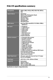
x 9.0 in . M2A-VM specifications summary Manageability WfM2.0, DMI2.0, WOL by PME, WOR, PXE, WOR by PME Special features ASUS Q-Fan ASUS C.P.R. (CPU Parameter Recall) ASUS CrashFree BIOS 3 ASUS EZ Flash 2 ASUS O.C. xi Profile ASUS MyLogo2™ ASUS Music Alarm BIOS features 8 Mb Flash ROM, Award BIOS, PnP, DMI2.0, WfM2.0, SM BIOS 2.3 Rear panel 1 x Parallel port 1 x LAN (RJ-45) port 4 x USB 2.0 ports...
x 9.0 in . M2A-VM specifications summary Manageability WfM2.0, DMI2.0, WOL by PME, WOR, PXE, WOR by PME Special features ASUS Q-Fan ASUS C.P.R. (CPU Parameter Recall) ASUS CrashFree BIOS 3 ASUS EZ Flash 2 ASUS O.C. xi Profile ASUS MyLogo2™ ASUS Music Alarm BIOS features 8 Mb Flash ROM, Award BIOS, PnP, DMI2.0, WfM2.0, SM BIOS 2.3 Rear panel 1 x Parallel port 1 x LAN (RJ-45) port 4 x USB 2.0 ports...

Motherboard Installation Guide
Page 35
... Blue Lime Pink Headset. 2-channel Line In Headphone/Front Mic In 4-channel Surround Front Speaker Out Mic In 6-channel Surround Front Speaker Out Center/Subwoofer ASUS M2A-VM 1-23 Line Out port (lime). This port is for the function of this port becomes Front Speaker Out. 6. Line In port (light blue). Refer to...
... Blue Lime Pink Headset. 2-channel Line In Headphone/Front Mic In 4-channel Surround Front Speaker Out Mic In 6-channel Surround Front Speaker Out Center/Subwoofer ASUS M2A-VM 1-23 Line Out port (lime). This port is for the function of this port becomes Front Speaker Out. 6. Line In port (light blue). Refer to...

Motherboard Installation Guide
Page 41
...USB_P5USB_P5+ GND M2A-VM.USB.2.0.connectors Never connect a 1394 cable to receive stereo audio input from the optical drive to the 4-pin CD-IN connector labeled CD on the motherboard. • Connect speakers or a headphone to the output jack on the front or rear panel for USB 2.0...output. Doing so will damage the motherboard! Optical drive audio in connector (4-pin CD) These connectors allow you to the USB connectors. CD (black) Left Audio Channel Ground Ground Right Audio Channel M2A-VM ® M2A-VM Internal audio connector To activate ASUS Music Alarm: • Connect the...
...USB_P5USB_P5+ GND M2A-VM.USB.2.0.connectors Never connect a 1394 cable to receive stereo audio input from the optical drive to the 4-pin CD-IN connector labeled CD on the motherboard. • Connect speakers or a headphone to the output jack on the front or rear panel for USB 2.0...output. Doing so will damage the motherboard! Optical drive audio in connector (4-pin CD) These connectors allow you to the USB connectors. CD (black) Left Audio Channel Ground Ground Right Audio Channel M2A-VM ® M2A-VM Internal audio connector To activate ASUS Music Alarm: • Connect the...

Motherboard Installation Guide
Page 42
.... Connect one end of the motherboard high-definition audio capability. • If you connect a high-definition front panel audio module to this connector to avail of the front panel audio I /O module that supports either High Definition Audio or AC`97 audio standard. M2A-VM ® GND PRESENCE# SENSE1_RETUR... NC NC NC MIC2 MICPWR Line out_R NC Line out_L PORT1 L PORT1 R PORT2 R SENSE_SEND PORT2 L M2A-VM Analog front panel connector • We recommend that the Front Panel Type item in the BIOS is purchased separately. Connect the serial port module cable to the connector, then ...
.... Connect one end of the motherboard high-definition audio capability. • If you connect a high-definition front panel audio module to this connector to avail of the front panel audio I /O module that supports either High Definition Audio or AC`97 audio standard. M2A-VM ® GND PRESENCE# SENSE1_RETUR... NC NC NC MIC2 MICPWR Line out_R NC Line out_L PORT1 L PORT1 R PORT2 R SENSE_SEND PORT2 L M2A-VM Analog front panel connector • We recommend that the Front Panel Type item in the BIOS is purchased separately. Connect the serial port module cable to the connector, then ...

Motherboard Installation Guide
Page 44
... connector supports several chassis-mounted functions. PWR Ground Reset Ground M2A-VM ® M2A-VM.System.panel.connector IDE_LED RESET PWRSW * Requires an ATX power supply. • System power LED This 2-pin connector is for the chassis-mounted reset button for system reboot without ...OFF. • Reset button This 2-pin connector is for the chassis-mounted system warning speaker. PLED SPEAKER PLED+ PLED+5V Ground Ground Speaker PANEL IDE_LED+ IDE_LED- Connect the HDD Activity LED cable to hear system beeps and warnings. • Power/Soft-off the system power. 1-32 Chapter...
... connector supports several chassis-mounted functions. PWR Ground Reset Ground M2A-VM ® M2A-VM.System.panel.connector IDE_LED RESET PWRSW * Requires an ATX power supply. • System power LED This 2-pin connector is for the chassis-mounted reset button for system reboot without ...OFF. • Reset button This 2-pin connector is for the chassis-mounted system warning speaker. PLED SPEAKER PLED+ PLED+5V Ground Ground Speaker PANEL IDE_LED+ IDE_LED- Connect the HDD Activity LED cable to hear system beeps and warnings. • Power/Soft-off the system power. 1-32 Chapter...

Motherboard Installation Guide
Page 68
...] [1024] [2048] [4096] 2.4.4 Onboard Device Configuration Advanced Phoenix-Award BIOS CMOS Setup Utility Onboard Device Configuration South OnChip IDE Device South OnChip PCI Device Front Panel Type Primary Display Adapter Onboard LAN Onboard LAN Boot ROM Serial Port1 Address Parallel Port Address Parallel Port Mode x ECP Mode Use DMA [HD Audio...
...] [1024] [2048] [4096] 2.4.4 Onboard Device Configuration Advanced Phoenix-Award BIOS CMOS Setup Utility Onboard Device Configuration South OnChip IDE Device South OnChip PCI Device Front Panel Type Primary Display Adapter Onboard LAN Onboard LAN Boot ROM Serial Port1 Address Parallel Port Address Parallel Port Mode x ECP Mode Use DMA [HD Audio...

Motherboard Installation Guide
Page 69
...SATA Type [Enabled] [RAID Controller] Item Specific Help Onboard SATA Controller [Enabled] Allows you to set the front panel audio connector (AAFP) mode to legacy AC`97 or high-definition audio depending on the audio standard that the front...] [AHCI Controller] Front Panel Type [HD Audio] Allows you to enable or disable the onboard Serial ATA controller. Configuration options: [Disabled] [Enabled] Onboard SATA Type [IDE Controller] Allows you to enable or disable the IDE DMA transfer access. Configuration options: [Disabled] [Enabled] ASUS M2A-VM 2-25 Configuration options: [...
...SATA Type [Enabled] [RAID Controller] Item Specific Help Onboard SATA Controller [Enabled] Allows you to set the front panel audio connector (AAFP) mode to legacy AC`97 or high-definition audio depending on the audio standard that the front...] [AHCI Controller] Front Panel Type [HD Audio] Allows you to enable or disable the onboard Serial ATA controller. Configuration options: [Disabled] [Enabled] Onboard SATA Type [IDE Controller] Allows you to enable or disable the IDE DMA transfer access. Configuration options: [Disabled] [Enabled] ASUS M2A-VM 2-25 Configuration options: [...

M2A-VM Premium user's manual
Page 3
Contents Notices...vi Safety information vii M2A-VM specifications summary x Chapter 1: Product introduction 1.1 Welcome 1-2 1.2 Package contents 1-2 1.3 Special features 1-2 1.3.1 Product highlights 1-2 1.3.2 Innovative ASUS features 1-4 1.4 Before you proceed 1-6 1.5 Motherboard overview 1-7 1.5.1 Motherboard layout 1-7 1.5.2 Placement direction 1-8 1.5.3 Screw holes 1-8 1.6 Central Processing Unit (CPU 1-9 1.6.1 Installing the CPU 1-9 1.6.2 ...PCI Express x16 slot 1-20 1.9 Jumpers 1-21 1.10 Connectors 1-23 1.10.1 Rear panel connectors 1-23 1.10.2 Internal connectors 1-25 iii
Contents Notices...vi Safety information vii M2A-VM specifications summary x Chapter 1: Product introduction 1.1 Welcome 1-2 1.2 Package contents 1-2 1.3 Special features 1-2 1.3.1 Product highlights 1-2 1.3.2 Innovative ASUS features 1-4 1.4 Before you proceed 1-6 1.5 Motherboard overview 1-7 1.5.1 Motherboard layout 1-7 1.5.2 Placement direction 1-8 1.5.3 Screw holes 1-8 1.6 Central Processing Unit (CPU 1-9 1.6.1 Installing the CPU 1-9 1.6.2 ...PCI Express x16 slot 1-20 1.9 Jumpers 1-21 1.10 Connectors 1-23 1.10.1 Rear panel connectors 1-23 1.10.2 Internal connectors 1-25 iii

M2A-VM Premium user's manual
Page 11
xi M2A-VM specifications summary Manageability WfM2.0, DMI2.0, WOL by PME, WOR, PXE, WOR by PME Special features ASUS Q-Fan ASUS C.P.R. (CPU Parameter Recall) ASUS CrashFree BIOS 3 ASUS EZ Flash 2 ASUS O.C. x 9.0 in . Profile ASUS MyLogo2™ ASUS Music Alarm BIOS features 8 Mb Flash ROM, Award BIOS, PnP, DMI2.0, WfM2.0, SM BIOS 2.3 Rear panel 1 x Parallel port 1 x LAN (RJ-45) port 4 x USB 2.0 ports...
xi M2A-VM specifications summary Manageability WfM2.0, DMI2.0, WOL by PME, WOR, PXE, WOR by PME Special features ASUS Q-Fan ASUS C.P.R. (CPU Parameter Recall) ASUS CrashFree BIOS 3 ASUS EZ Flash 2 ASUS O.C. x 9.0 in . Profile ASUS MyLogo2™ ASUS Music Alarm BIOS features 8 Mb Flash ROM, Award BIOS, PnP, DMI2.0, WfM2.0, SM BIOS 2.3 Rear panel 1 x Parallel port 1 x LAN (RJ-45) port 4 x USB 2.0 ports...

M2A-VM Premium user's manual
Page 35
... Gigabit connection to the audio configuration table for a PS/2 mouse. 2. This port connects a headphone or a speaker. 1.10 Connectors 1.10.1 Rear panel connectors 1 2 3 4 5 6 11 10 9 8 7 1. LAN port LED indications Activity/Link LED Status Description OFF No link ORANGE Linked ...Headset. 2-channel Line In Headphone/Front Mic In 4-channel Surround Front Speaker Out Mic In 6-channel Surround Front Speaker Out Center/Subwoofer ASUS M2A-VM 1-23 Line Out port (lime). In 4channel/ 6-channel configuration, the function of the audio ports in 2, 4, or 6,-channel...
... Gigabit connection to the audio configuration table for a PS/2 mouse. 2. This port connects a headphone or a speaker. 1.10 Connectors 1.10.1 Rear panel connectors 1 2 3 4 5 6 11 10 9 8 7 1. LAN port LED indications Activity/Link LED Status Description OFF No link ORANGE Linked ...Headset. 2-channel Line In Headphone/Front Mic In 4-channel Surround Front Speaker Out Mic In 6-channel Surround Front Speaker Out Center/Subwoofer ASUS M2A-VM 1-23 Line Out port (lime). In 4channel/ 6-channel configuration, the function of the audio ports in 2, 4, or 6,-channel...

M2A-VM Premium user's manual
Page 41
... rear panel for USB 2.0 ports. Optical drive audio in connector (4-pin CD) These connectors allow you to receive stereo audio input from the optical drive to the 4-pin CD-IN connector labeled CD on the motherboard. • Connect speakers or a headphone to 480 Mbps connection speed. The USB 2.0 module is purchased separately. 8. ASUS M2A-VM...
... rear panel for USB 2.0 ports. Optical drive audio in connector (4-pin CD) These connectors allow you to receive stereo audio input from the optical drive to the 4-pin CD-IN connector labeled CD on the motherboard. • Connect speakers or a headphone to 480 Mbps connection speed. The USB 2.0 module is purchased separately. 8. ASUS M2A-VM...

M2A-VM Premium user's manual
Page 42
...to the connector, then install the module to [AC97]. M2A-VM ® COM1 PIN 1 M2A-VM.COM.port.connector 10. Front panel audio connector (10-1 pin AAFP) This connector is set the item to a slot opening at the back of the front panel audio I /O module that supports either High Definition Audio or...AC`97 audio standard. if you want to connect an AC`97 front panel audio module to this connector, make sure that you connect a high-definition front panel audio module to this connector to avail of the motherboard high-definition audio capability. • If you want to connect a ...
...to the connector, then install the module to [AC97]. M2A-VM ® COM1 PIN 1 M2A-VM.COM.port.connector 10. Front panel audio connector (10-1 pin AAFP) This connector is set the item to a slot opening at the back of the front panel audio I /O module that supports either High Definition Audio or...AC`97 audio standard. if you want to connect an AC`97 front panel audio module to this connector, make sure that you connect a high-definition front panel audio module to this connector to avail of the motherboard high-definition audio capability. • If you want to connect a ...

M2A-VM Premium user's manual
Page 44
PLED SPEAKER PLED+ PLED+5V Ground Ground Speaker PANEL IDE_LED+ IDE_LED- The system power LED lights up or flashes when data is read from or written to this connector. Connect the HDD Activity LED .... 1-32 Chapter 1: Product introduction The speaker allows you turn on the BIOS settings. System panel onnector (20-8 pin PANEL) This connector supports several chassis-mounted functions. PWR Ground Reset Ground M2A-VM ® M2A-VM.System.panel.connector IDE_LED RESET PWRSW * Requires an ATX power supply. • System power LED This 2-pin connector is for the system power...
PLED SPEAKER PLED+ PLED+5V Ground Ground Speaker PANEL IDE_LED+ IDE_LED- The system power LED lights up or flashes when data is read from or written to this connector. Connect the HDD Activity LED .... 1-32 Chapter 1: Product introduction The speaker allows you turn on the BIOS settings. System panel onnector (20-8 pin PANEL) This connector supports several chassis-mounted functions. PWR Ground Reset Ground M2A-VM ® M2A-VM.System.panel.connector IDE_LED RESET PWRSW * Requires an ATX power supply. • System power LED This 2-pin connector is for the system power...

M2A-VM Premium user's manual
Page 68
...] [1024] [2048] [4096] 2.4.4 Onboard Device Configuration Advanced Phoenix-Award BIOS CMOS Setup Utility Onboard Device Configuration South OnChip IDE Device South OnChip PCI Device Front Panel Type Primary Display Adapter Onboard LAN Onboard LAN Boot ROM Serial Port1 Address Parallel Port Address Parallel Port Mode x ECP Mode Use DMA [HD Audio...
...] [1024] [2048] [4096] 2.4.4 Onboard Device Configuration Advanced Phoenix-Award BIOS CMOS Setup Utility Onboard Device Configuration South OnChip IDE Device South OnChip PCI Device Front Panel Type Primary Display Adapter Onboard LAN Onboard LAN Boot ROM Serial Port1 Address Parallel Port Address Parallel Port Mode x ECP Mode Use DMA [HD Audio...

M2A-VM Premium user's manual
Page 69
...controller to enable or disable the IDE DMA transfer access. Configuration options: [IDE Controller] [RAID Controller] [AHCI Controller] Front Panel Type [HD Audio] Allows you to legacy AC`97 or high-definition audio depending on the audio standard that the front...] [Enabled] Onboard SATA Type [IDE Controller] Allows you to select the onboard Serial ATA type. Configuration options: [Disabled] [Enabled] ASUS M2A-VM 2-25 South OnChip IDE Device Advanced Phoenix-Award BIOS CMOS Setup Utility South OnChip IDE Device Select Menu IDE DMA transfer access OnChip IDE Channel0...
...controller to enable or disable the IDE DMA transfer access. Configuration options: [IDE Controller] [RAID Controller] [AHCI Controller] Front Panel Type [HD Audio] Allows you to legacy AC`97 or high-definition audio depending on the audio standard that the front...] [Enabled] Onboard SATA Type [IDE Controller] Allows you to select the onboard Serial ATA type. Configuration options: [Disabled] [Enabled] ASUS M2A-VM 2-25 South OnChip IDE Device Advanced Phoenix-Award BIOS CMOS Setup Utility South OnChip IDE Device Select Menu IDE DMA transfer access OnChip IDE Channel0...


