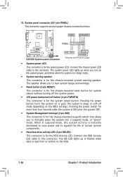
K8V-MX User's Manual for English Edition
Page 29
...Connectors This section describes and illustrates the rear panel and internal connectors on the motherboard. 1.10.1 Rear panel connectors 1 2 3 4 5 6 11 10 9 8 7 1. This 25-pin port connects a parallel printer, a scanner, or other audio sources. This port allows connection to a Local Area Network (LAN) ...connects a microphone. Line In port. Audio ports function variation Audio ports Light Blue Lime Pink Headphone /2-Channel Line In Line Out Mic In 4-Channel Rear Speaker Out Front Speaker Out Mic In 6-Channel Rear Speaker Out Front Speaker Out Bass/Center ASUS K8V-MX...
K8V-MX User's Manual for English Edition
Page 34
... 1 configuration. Serial ATA connectors (7-pin SATA1, SATA2) These connectors support the thin Serial ATA cables for the Intel® front panel audio cable allows convenient connection and control of audio devices. AGND +5VA BLINE_OUT_R BLINE_OUT_L MIC2 MICPWR Line out_R NC Line out_L R K8V-MX FP_AUDIO K8V-MX Front panel audio connector 1-24 Chapter 1: Product Introduction
K8V-MX User's Manual for English Edition
Page 36
... to manually place the system into a suspend mode, or "green" mode. Connect the HDD Activity LED cable to the HDD. 1-26 Chapter 1: Product Introduction PLED SPEAKER PLED+ PLED+5V Ground Ground Speaker PANEL IDELED+ IDELED PWR Ground Reset Ground R K8V-MX K8V-MX System panel connector IDE_LED RESET PWRSW * Requires an ATX power supply. • System power...