
K7V-T User Manual
Page 1
R K7V-T Slot A Motherboard USER'S MANUAL
R K7V-T Slot A Motherboard USER'S MANUAL

K7V-T User Manual
Page 4
CONTENTS 1. HARDWARE SETUP 14 3.1 K7V-T Motherboard Layout 14 3.2 Layout Contents 15 3.3 Hardware Setup Procedure 17 3.4 Motherboard Settings 17 3.5 System Memory (DIMM 22 3.5.1 General DIMM Notes 22 3.5.2 DIMM Memory ... 3.8 External Connectors 35 3.9 Starting Up the First Time 47 4. FEATURES 8 2.1 The ASUS K7V-T Motherboard 8 2.1.1 Specifications 8 2.1.1.1 Optional Components 9 2.1.2 Performance 10 2.1.3 Intelligence (only with optional hardware monitor) ........ 11 2.2 K7V-T Motherboard Components 12 3. BIOS SETUP 49 4.1 Managing and Updating Your BIOS 49 4.1.1 Upon First...
CONTENTS 1. HARDWARE SETUP 14 3.1 K7V-T Motherboard Layout 14 3.2 Layout Contents 15 3.3 Hardware Setup Procedure 17 3.4 Motherboard Settings 17 3.5 System Memory (DIMM 22 3.5.1 General DIMM Notes 22 3.5.2 DIMM Memory ... 3.8 External Connectors 35 3.9 Starting Up the First Time 47 4. FEATURES 8 2.1 The ASUS K7V-T Motherboard 8 2.1.1 Specifications 8 2.1.1.1 Optional Components 9 2.1.2 Performance 10 2.1.3 Intelligence (only with optional hardware monitor) ........ 11 2.2 K7V-T Motherboard Components 12 3. BIOS SETUP 49 4.1 Managing and Updating Your BIOS 49 4.1.1 Upon First...

K7V-T User Manual
Page 5
... 5. APPENDIX 103 7.1 PCI-L101 Fast Ethernet Card 103 7.2 Modem Riser 105 7.3 Glossary 107 ASUS K7V-T User's Manual 5 SOFTWARE REFERENCE 95 6.1 ASUS PC Probe 95 6.2 YAMAHA XGStudio 100 7. SOFTWARE SETUP 83 5.1 Operating Systems 83 5.1.1 Windows 98 First Time Installation 83 5.2 K7V-T Series Motherboard Support CD 84 5.3 Registry patch for VIA Chipset 85 5.4 VIA PCI IRQ Routing...
... 5. APPENDIX 103 7.1 PCI-L101 Fast Ethernet Card 103 7.2 Modem Riser 105 7.3 Glossary 107 ASUS K7V-T User's Manual 5 SOFTWARE REFERENCE 95 6.1 ASUS PC Probe 95 6.2 YAMAHA XGStudio 100 7. SOFTWARE SETUP 83 5.1 Operating Systems 83 5.1.1 Windows 98 First Time Installation 83 5.2 K7V-T Series Motherboard Support CD 84 5.3 Registry patch for VIA Chipset 85 5.4 VIA PCI IRQ Routing...

K7V-T User Manual
Page 7
...). INTRODUCTION Manual information and checklist 2. SOFTWARE REFERENCE Reference material for this motherboard. HARDWARE SETUP Instructions on setting up if your retailer. 1.2.1 Motherboard (1) ASUS Motherboard (1) Universal Retention Mechanism (1) ASUS 2-port USB Connector Set (1) 40-pin 80-conductor ribbon cable for ...APPENDIX Optional items and general reference 1.2 Item Checklist Check that your package is divided into the following sections: 1. ASUS K7V-T User's Manual 7 INTRODUCTION 1.1 How This Manual Is Organized This manual is complete. Make sure that your ...
...). INTRODUCTION Manual information and checklist 2. SOFTWARE REFERENCE Reference material for this motherboard. HARDWARE SETUP Instructions on setting up if your retailer. 1.2.1 Motherboard (1) ASUS Motherboard (1) Universal Retention Mechanism (1) ASUS 2-port USB Connector Set (1) 40-pin 80-conductor ribbon cable for ...APPENDIX Optional items and general reference 1.2 Item Checklist Check that your package is divided into the following sections: 1. ASUS K7V-T User's Manual 7 INTRODUCTION 1.1 How This Manual Is Organized This manual is complete. Make sure that your ...

K7V-T User Manual
Page 8
...'s Manual designed for Windows 98 compatibility, built-in firmware-based virus protection, and autodetection of the AMD Athlon™ processors-including 1GHz- FEATURES 2.1 The ASUS K7V-T Motherboard The ASUS K7V-T motherboard is enabled. PCI supports up to 1.5GB. • JumperFree™ Mode: Allows processor settings and easy overclocking of frequency and Vcore voltage all through BIOS...
...'s Manual designed for Windows 98 compatibility, built-in firmware-based virus protection, and autodetection of the AMD Athlon™ processors-including 1GHz- FEATURES 2.1 The ASUS K7V-T Motherboard The ASUS K7V-T motherboard is enabled. PCI supports up to 1.5GB. • JumperFree™ Mode: Allows processor settings and easy overclocking of frequency and Vcore voltage all through BIOS...
K7V-T User Manual
Page 9
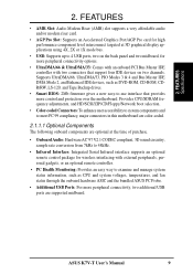
...: Supports up to 48kHz. • Infrared Interface: Integrated Serial Infrared interface supports an optional remote control package for more control and protection over the motherboard. 2. FEATURES • AMR Slot: Audio Modem Riser (AMR) slot supports a very affordable audio and/or modem riser card. • AGP ...; Color-coded Connectors: To enhance user accessibility to system components and to meet PC 99 compliancy, major connectors in this motherboard are color-coded. 2.1.1.1 Optional Components The following onboard components are supported midboard. ASUS K7V-T User's Manual 9
...: Supports up to 48kHz. • Infrared Interface: Integrated Serial Infrared interface supports an optional remote control package for more control and protection over the motherboard. 2. FEATURES • AMR Slot: Audio Modem Riser (AMR) slot supports a very affordable audio and/or modem riser card. • AGP ...; Color-coded Connectors: To enhance user accessibility to system components and to meet PC 99 compliancy, major connectors in this motherboard are color-coded. 2.1.1.1 Optional Components The following onboard components are supported midboard. ASUS K7V-T User's Manual 9

K7V-T User Manual
Page 10
....6MB/s. With these features implemented in the OS, PCs can operate at 200MHz while system memory operates at reduced power consumption of the motherboard meets PC 99 compliancy. The VCM's core design provides up to 50% higher SDRAM speed at 133MHz or 100MHz. • High-... Power Management (OSPM) functionality. This motherboard also supports standard SDRAM, which is no need to upgrade current EIDE/IDE drives and host systems. (UltraDMA/66 requires a 40-pin 80-conductor cable to be enabled and/or for Windows 95/98/NT. 10 ASUS K7V-T User's Manual FEATURES Performance 2. FEATURES...
....6MB/s. With these features implemented in the OS, PCs can operate at 200MHz while system memory operates at reduced power consumption of the motherboard meets PC 99 compliancy. The VCM's core design provides up to 50% higher SDRAM speed at 133MHz or 100MHz. • High-... Power Management (OSPM) functionality. This motherboard also supports standard SDRAM, which is no need to upgrade current EIDE/IDE drives and host systems. (UltraDMA/66 requires a 40-pin 80-conductor cable to be enabled and/or for Windows 95/98/NT. 10 ASUS K7V-T User's Manual FEATURES Performance 2. FEATURES...

K7V-T User Manual
Page 11
... configuration and management. • Auto Fan Off: The system fans will power off automatically even in the world! 2. With this motherboard to critical motherboard components. All the fans are set for its normal RPM range and alarm thresholds. • Voltage Monitoring and Alert: Processor and ...system damage, the CPU, power supply, and system fans can access their computer from anywhere in sleep mode. FEATURES Intelligence ASUS K7V-T User's Manual 11 FEATURES 2.1.3 Intelligence (only with this feature, users can be turned on remotely through an internal or external modem. 2.
... configuration and management. • Auto Fan Off: The system fans will power off automatically even in the world! 2. With this motherboard to critical motherboard components. All the fans are set for its normal RPM range and alarm thresholds. • Voltage Monitoring and Alert: Processor and ...system damage, the CPU, power supply, and system fans can access their computer from anywhere in sleep mode. FEATURES Intelligence ASUS K7V-T User's Manual 11 FEATURES 2.1.3 Intelligence (only with this feature, users can be turned on remotely through an internal or external modem. 2.

K7V-T User Manual
Page 12
FEATURES 2. Location Processor Support Slot A for locations. FEATURES Components 2.2 K7V-T Motherboard Components See opposite page for AMD Athlon™ Processors 1 Frequency Selection DIP Switches 5 Chipsets/Chips North Bridge: VIA VT8371™ (System Controller 2 South Bridge/Super I/O: ... Power and Speed Monitoring Connectors Power ATX Power Supply Connector 4 Special Feature Onboard LED (Standby Power Warning 19 Form Factor ATX, 305mm x 244mm (12" x 9.6") 12 ASUS K7V-T User's Manual
FEATURES 2. Location Processor Support Slot A for locations. FEATURES Components 2.2 K7V-T Motherboard Components See opposite page for AMD Athlon™ Processors 1 Frequency Selection DIP Switches 5 Chipsets/Chips North Bridge: VIA VT8371™ (System Controller 2 South Bridge/Super I/O: ... Power and Speed Monitoring Connectors Power ATX Power Supply Connector 4 Special Feature Onboard LED (Standby Power Warning 19 Form Factor ATX, 305mm x 244mm (12" x 9.6") 12 ASUS K7V-T User's Manual

K7V-T User Manual
Page 13
FEATURES Component Locations 2. FEATURES K7V-T Motherboard Component Locations 1 2 3 45 6 7 26 25 24 23 22 21 20 19 18 17 16 15 14 13 12 11 10 9 8 ASUS K7V-T User's Manual 13 2.
FEATURES Component Locations 2. FEATURES K7V-T Motherboard Component Locations 1 2 3 45 6 7 26 25 24 23 22 21 20 19 18 17 16 15 14 13 12 11 10 9 8 ASUS K7V-T User's Manual 13 2.

K7V-T User Manual
Page 14
H/W SETUP Motherboard Layout 3. HARDWARE SETUP 3.1 K7V-T Motherboard Layout GAME_AUDIO 24.5cm (9.64in) PS/2 T: Mouse B: Keyboard F_FAN PWR_FAN VIO DIMM3 (64/72 bit, 168-pin module) DIMM2 (64/72 bit, 168-pin module) ...) AUDIOEN Aureal Audio Chipset SPDIFOUT USB Hub Au9254 WOLCON IR WOR USB3A IDELED USB3 PANEL Grayed items are optional at the time of purchase. 14 ASUS K7V-T User's Manual PRIMARY IDE SECONDARY IDE 2Mbit Flash EEPROM (Programmable BIOS) 30.6cm (12in) 3.
H/W SETUP Motherboard Layout 3. HARDWARE SETUP 3.1 K7V-T Motherboard Layout GAME_AUDIO 24.5cm (9.64in) PS/2 T: Mouse B: Keyboard F_FAN PWR_FAN VIO DIMM3 (64/72 bit, 168-pin module) DIMM2 (64/72 bit, 168-pin module) ...) AUDIOEN Aureal Audio Chipset SPDIFOUT USB Hub Au9254 WOLCON IR WOR USB3A IDELED USB3 PANEL Grayed items are optional at the time of purchase. 14 ASUS K7V-T User's Manual PRIMARY IDE SECONDARY IDE 2Mbit Flash EEPROM (Programmable BIOS) 30.6cm (12in) 3.

K7V-T User Manual
Page 15
3. HARDWARE SETUP 3.2 Layout Contents Motherboard Settings 1) JEN 2) 3VSBSLT 3) AUDIO_CODEC 4) VIO 5) DSW 6) VID1, VID2, VID3 p.18 JumperFree™ Mode (JEN) p.18 Vaux Setting (+3V/+3VSB) p.19 Onboard Audio Setting (Enable.../Disable...) p....) 19) ATXPWR p.43 ATX Power Supply Connector (20 pins) 20) USBPORT p.44 USB Connector Set (10-1 pins) 21) SPDIFOUT p.44 Digital Audio Interface Connector (3 pins) ASUS K7V-T User's Manual 15 H/W SETUP Layout Contents 3.
3. HARDWARE SETUP 3.2 Layout Contents Motherboard Settings 1) JEN 2) 3VSBSLT 3) AUDIO_CODEC 4) VIO 5) DSW 6) VID1, VID2, VID3 p.18 JumperFree™ Mode (JEN) p.18 Vaux Setting (+3V/+3VSB) p.19 Onboard Audio Setting (Enable.../Disable...) p....) 19) ATXPWR p.43 ATX Power Supply Connector (20 pins) 20) USBPORT p.44 USB Connector Set (10-1 pins) 21) SPDIFOUT p.44 Digital Audio Interface Connector (3 pins) ASUS K7V-T User's Manual 15 H/W SETUP Layout Contents 3.

K7V-T User Manual
Page 17
... working on the bag that the ATX power supply is switched off before handling computer components. Frequency Selection ASUS K7V-T User's Manual 17 Unplug your computer. 1. The white block represents the switch's position. Computer motherboards and expansion cards contain very delicate Integrated Circuit (IC) chips. Ensure that came with the component whenever the...
... working on the bag that the ATX power supply is switched off before handling computer components. Frequency Selection ASUS K7V-T User's Manual 17 Unplug your computer. 1. The white block represents the switch's position. Computer motherboards and expansion cards contain very delicate Integrated Circuit (IC) chips. Ensure that came with the component whenever the...

K7V-T User Manual
Page 18
... 3 VSB. H/W SETUP Motherboard Settings 01 01 01 01 01 01 3. IMPORTANT: In JumperFree™ mode, all DIP switches (DSW) must be set to enable or disable the JumperFree™ mode. Setting 3 Volt 3 VSB 3VSBSLT [1-2] [2-3] (default) 3VSBSLT 12 23 Add 3 Volt Add 3 VSB (Default) K7V-T ® K7V-T PCI 3Volt Selection 18 ASUS K7V-T User's Manual The...
... 3 VSB. H/W SETUP Motherboard Settings 01 01 01 01 01 01 3. IMPORTANT: In JumperFree™ mode, all DIP switches (DSW) must be set to enable or disable the JumperFree™ mode. Setting 3 Volt 3 VSB 3VSBSLT [1-2] [2-3] (default) 3VSBSLT 12 23 Add 3 Volt Add 3 VSB (Default) K7V-T ® K7V-T PCI 3Volt Selection 18 ASUS K7V-T User's Manual The...

K7V-T User Manual
Page 19
... life. Setting Enable AUDIO CODEC [1-2] [1-2] [1-2] [1-2] (default) Disable [2-3] [2-3] [2-3] [2-3] Enable Onboard Audio Codec (Default) Disable Onboard Audio Codec K7V-T ® 3 2 2 1 K7V-T Audio Codec Setting 4) I/O Voltage Setting (VIO) VIO allows you to select the voltage supplied to the DRAM, chipset, AGP, PCI, and ... primary AMR on the AMR slot (see AMR Slot later in 4.4.2 I /O buffer. ASUS K7V-T User's Manual 19 The default voltage (3.31V) should be disabled. H/W SETUP Motherboard Settings 01 01 01 01 01 01 3. Using a higher voltage may help when overclocking...
... life. Setting Enable AUDIO CODEC [1-2] [1-2] [1-2] [1-2] (default) Disable [2-3] [2-3] [2-3] [2-3] Enable Onboard Audio Codec (Default) Disable Onboard Audio Codec K7V-T ® 3 2 2 1 K7V-T Audio Codec Setting 4) I/O Voltage Setting (VIO) VIO allows you to select the voltage supplied to the DRAM, chipset, AGP, PCI, and ... primary AMR on the AMR slot (see AMR Slot later in 4.4.2 I /O buffer. ASUS K7V-T User's Manual 19 The default voltage (3.31V) should be disabled. H/W SETUP Motherboard Settings 01 01 01 01 01 01 3. Using a higher voltage may help when overclocking...
K7V-T User Manual
Page 20
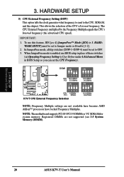
...JumperFree mode is enabled, use this feature, JEN [see 3.5 System Memory (DIMM). 3. IMPORTANT: 1. NOTE: The motherboard supports PC100 / PC133 DIMMs or VC SDRAMsfor system memory. H/W SETUP Motherboard Settings 20 ASUS K7V-T User's Manual In JumperFree mode, all dip switches (DSW-1-DSW-4) must be set to User Define under 4.4 Advanced ... be set the CPU Frequency). 01 01 01 DSW ON ON 1234 CPU 100.00MHz PCI 33.33MHz ON K7V-T ® 1234 CPU 105MHz PCI 35MHz K7V-T CPU External Frequency Selection 1234 103.00MHz 34.33MHz ON 1234 110.00MHz 36.67MHz NOTE: Frequency Multiple settings...
...JumperFree mode is enabled, use this feature, JEN [see 3.5 System Memory (DIMM). 3. IMPORTANT: 1. NOTE: The motherboard supports PC100 / PC133 DIMMs or VC SDRAMsfor system memory. H/W SETUP Motherboard Settings 20 ASUS K7V-T User's Manual In JumperFree mode, all dip switches (DSW-1-DSW-4) must be set to User Define under 4.4 Advanced ... be set the CPU Frequency). 01 01 01 DSW ON ON 1234 CPU 100.00MHz PCI 33.33MHz ON K7V-T ® 1234 CPU 105MHz PCI 35MHz K7V-T CPU External Frequency Selection 1234 103.00MHz 34.33MHz ON 1234 110.00MHz 36.67MHz NOTE: Frequency Multiple settings...

K7V-T User Manual
Page 21
..., VID3) This jumpers allow you to the CPU VID configuration. Premature wearing of the processor may result when overclocking. K7V-T ® K7V-T CPU Core Voltage Selection 01 01 01 1234 VID3 1234 1234 VID2 VID1 2/2.05Volts 1.9/1.95Volts 1.8/1.85Volts 1234 VID3 1234 1234...1.3/1.35olts CPU Default/ JumperFree (Default) ASUS K7V-T User's Manual 21 It is generated according to manually adjust the CPU core voltage. For each jumper setting, there are two voltage options, depending on the CPU used. H/W SETUP Motherboard Settings 3. WARNING! HARDWARE SETUP External Frequency...
..., VID3) This jumpers allow you to the CPU VID configuration. Premature wearing of the processor may result when overclocking. K7V-T ® K7V-T CPU Core Voltage Selection 01 01 01 1234 VID3 1234 1234 VID2 VID1 2/2.05Volts 1.9/1.95Volts 1.8/1.85Volts 1234 VID3 1234 1234...1.3/1.35olts CPU Default/ JumperFree (Default) ASUS K7V-T User's Manual 21 It is generated according to manually adjust the CPU core voltage. For each jumper setting, there are two voltage options, depending on the CPU used. H/W SETUP Motherboard Settings 3. WARNING! HARDWARE SETUP External Frequency...

K7V-T User Manual
Page 22
...with memory chips) of 16, 32, 64, 128MB, 256 or 512MB. double-sided come in 32, 64, 128, 256, 512MB. 22 ASUS K7V-T User's Manual Install memory in any combination as follows: IMPORTANT • For optimum signal integrity, inserting the DIMMs in the following order is ...with the current PC133/PC100 SDRAM specification. • DO NOT attempt to form a memory size between 16MB and 1.5GB. stability. • This motherboard does NOT support registered memory. • SDRAM chips are available for best performance vs. to mix SDRAMs with 9 chips per side (standard 8 chips...
...with memory chips) of 16, 32, 64, 128MB, 256 or 512MB. double-sided come in 32, 64, 128, 256, 512MB. 22 ASUS K7V-T User's Manual Install memory in any combination as follows: IMPORTANT • For optimum signal integrity, inserting the DIMMs in the following order is ...with the current PC133/PC100 SDRAM specification. • DO NOT attempt to form a memory size between 16MB and 1.5GB. stability. • This motherboard does NOT support registered memory. • SDRAM chips are available for best performance vs. to mix SDRAMs with 9 chips per side (standard 8 chips...

K7V-T User Manual
Page 23
... RFU Unbuffered Buffered Voltage Key Position 5.0V Reserved 3.3V The notches on the DIMM module will only fit in the orientation shown. This motherboard supports four clock signals. ASUS K7V-T User's Manual 23 HARDWARE SETUP 3.5.2 DIMM Memory Installation Insert the module(s) as shown. Because the number of the breaks, the module will shift...
... RFU Unbuffered Buffered Voltage Key Position 5.0V Reserved 3.3V The notches on the DIMM module will only fit in the orientation shown. This motherboard supports four clock signals. ASUS K7V-T User's Manual 23 HARDWARE SETUP 3.5.2 DIMM Memory Installation Insert the module(s) as shown. Because the number of the breaks, the module will shift...

K7V-T User Manual
Page 25
... may be connected to the processor with heatsink and fan (top view) 3.6.1 Quick CPU Installation Procedure 1. Install the Universal Retention Mechanism onto the motherboard. 3. Insert the processor. 3. AMD Athlon™ processor with thermal grease and retention clip. Be sure that there is working. HARDWARE SETUP ... are those with three-pin fans that your processor are provided for an AMD Athlon™ processor. H/W SETUP CPU ASUS K7V-T User's Manual 25 The appearance of your retention mechanism and fan may install an auxiliary chassis fan, if necessary. 2. WARNING!
... may be connected to the processor with heatsink and fan (top view) 3.6.1 Quick CPU Installation Procedure 1. Install the Universal Retention Mechanism onto the motherboard. 3. Insert the processor. 3. AMD Athlon™ processor with thermal grease and retention clip. Be sure that there is working. HARDWARE SETUP ... are those with three-pin fans that your processor are provided for an AMD Athlon™ processor. H/W SETUP CPU ASUS K7V-T User's Manual 25 The appearance of your retention mechanism and fan may install an auxiliary chassis fan, if necessary. 2. WARNING!


