
K7V-T User Manual
Page 1
R K7V-T Slot A Motherboard USER'S MANUAL
R K7V-T Slot A Motherboard USER'S MANUAL

K7V-T User Manual
Page 4
...4.1.1 Upon First Use of the Computer System 49 4.1.2 Updating BIOS Procedures 50 4 ASUS K7V-T User's Manual HARDWARE SETUP 14 3.1 K7V-T Motherboard Layout 14 3.2 Layout Contents 15 3.3 Hardware Setup Procedure 17 3.4 Motherboard Settings 17 3.5 System Memory (DIMM 22 3.5.1 General DIMM Notes 22 3.5.2 DIMM Memory... 33 3.8 External Connectors 35 3.9 Starting Up the First Time 47 4. CONTENTS 1. FEATURES 8 2.1 The ASUS K7V-T Motherboard 8 2.1.1 Specifications 8 2.1.1.1 Optional Components 9 2.1.2 Performance 10 2.1.3 Intelligence (only with optional hardware monitor) ........ 11...
...4.1.1 Upon First Use of the Computer System 49 4.1.2 Updating BIOS Procedures 50 4 ASUS K7V-T User's Manual HARDWARE SETUP 14 3.1 K7V-T Motherboard Layout 14 3.2 Layout Contents 15 3.3 Hardware Setup Procedure 17 3.4 Motherboard Settings 17 3.5 System Memory (DIMM 22 3.5.1 General DIMM Notes 22 3.5.2 DIMM Memory... 33 3.8 External Connectors 35 3.9 Starting Up the First Time 47 4. CONTENTS 1. FEATURES 8 2.1 The ASUS K7V-T Motherboard 8 2.1.1 Specifications 8 2.1.1.1 Optional Components 9 2.1.2 Performance 10 2.1.3 Intelligence (only with optional hardware monitor) ........ 11...

K7V-T User Manual
Page 5
... 95 6.2 YAMAHA XGStudio 100 7. APPENDIX 103 7.1 PCI-L101 Fast Ethernet Card 103 7.2 Modem Riser 105 7.3 Glossary 107 ASUS K7V-T User's Manual 5 SOFTWARE SETUP 83 5.1 Operating Systems 83 5.1.1 Windows 98 First Time Installation 83 5.2 K7V-T Series Motherboard Support CD 84 5.3 Registry patch for VIA Chipset 85 5.4 VIA PCI IRQ Routing Miniport Driver 86 5.5 AUDIO Driver...
... 95 6.2 YAMAHA XGStudio 100 7. APPENDIX 103 7.1 PCI-L101 Fast Ethernet Card 103 7.2 Modem Riser 105 7.3 Glossary 107 ASUS K7V-T User's Manual 5 SOFTWARE SETUP 83 5.1 Operating Systems 83 5.1.1 Windows 98 First Time Installation 83 5.2 K7V-T Series Motherboard Support CD 84 5.3 Registry patch for VIA Chipset 85 5.4 VIA PCI IRQ Routing Miniport Driver 86 5.5 AUDIO Driver...

K7V-T User Manual
Page 7
... Manual Is Organized This manual is inadequate. APPENDIX Optional items and general reference 1.2 Item Checklist Check that your retailer. 1.2.1 Motherboard (1) ASUS Motherboard (1) Universal Retention Mechanism (1) ASUS 2-port USB Connector Set (1) 40-pin 80-conductor ribbon cable for internal UltraDMA/66 or UltraDMA/33 IDE drives (1) Ribbon...used for the included software 7. Make sure that your power supply is divided into the following sections: 1. ASUS K7V-T User's Manual 7 SOFTWARE REFERENCE Reference material for this motherboard. 1. INTRODUCTION Sections/Checklist 1.
... Manual Is Organized This manual is inadequate. APPENDIX Optional items and general reference 1.2 Item Checklist Check that your retailer. 1.2.1 Motherboard (1) ASUS Motherboard (1) Universal Retention Mechanism (1) ASUS 2-port USB Connector Set (1) 40-pin 80-conductor ribbon cable for internal UltraDMA/66 or UltraDMA/33 IDE drives (1) Ribbon...used for the included software 7. Make sure that your power supply is divided into the following sections: 1. ASUS K7V-T User's Manual 7 SOFTWARE REFERENCE Reference material for this motherboard. 1. INTRODUCTION Sections/Checklist 1.

K7V-T User Manual
Page 8
...8482; Mode: Allows processor settings and easy overclocking of frequency and Vcore voltage all through BIOS, which allows hardware to an ASUS P2T-Cable. • Super Multi-I/O: Provides two high-speed UART compatible serial ports and one parallel port with support for the...-Up Support: Supports Wake-On-LAN and Wake-On-Ring. 8 ASUS K7V-T User's Manual Easy-to-use DIP switches instead of jumpers are included to 133MB/sec maximum throughput. FEATURES 2.1 The ASUS K7V-T Motherboard The ASUS K7V-T motherboard is optimized to deliver enhanced AMD Athlon™ processor system performance. ...
...8482; Mode: Allows processor settings and easy overclocking of frequency and Vcore voltage all through BIOS, which allows hardware to an ASUS P2T-Cable. • Super Multi-I/O: Provides two high-speed UART compatible serial ports and one parallel port with support for the...-Up Support: Supports Wake-On-LAN and Wake-On-Ring. 8 ASUS K7V-T User's Manual Easy-to-use DIP switches instead of jumpers are included to 133MB/sec maximum throughput. FEATURES 2.1 The ASUS K7V-T Motherboard The ASUS K7V-T motherboard is optimized to deliver enhanced AMD Athlon™ processor system performance. ...
K7V-T User Manual
Page 9
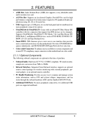
...the back panel and two midboard, for wireless interfacing with two connectors that provides more peripheral connectivity, two additional USB ports are supported midboard. ASUS K7V-T User's Manual 9 FEATURES Specifications 2. Supports UltraDMA/66, UltraDMA/33, PIO Modes 3 & 4 and Bus Master IDE DMA Mode 2,... and system voltages, temperatures, and fan status through the onboard hardware ASIC and the bundled ASUS PC Probe. • Additional USB Ports: For more control and protection over the motherboard. FEATURES • AMR Slot: Audio Modem Riser (AMR) slot supports a very affordable ...
...the back panel and two midboard, for wireless interfacing with two connectors that provides more peripheral connectivity, two additional USB ports are supported midboard. ASUS K7V-T User's Manual 9 FEATURES Specifications 2. Supports UltraDMA/66, UltraDMA/33, PIO Modes 3 & 4 and Bus Master IDE DMA Mode 2,... and system voltages, temperatures, and fan status through the onboard hardware ASIC and the bundled ASUS PC Probe. • Additional USB Ports: For more control and protection over the motherboard. FEATURES • AMR Slot: Audio Modem Riser (AMR) slot supports a very affordable ...

K7V-T User Manual
Page 10
...UltraDMA Mode 4.) • Concurrent PCI: Concurrent PCI allows multiple PCI transfers from PCI master buses to memory to CPU. • VCM/SDRAM Optimized Performance: This motherboard supports a new generation memory, NEC's 64Mb Virtual Channel Memory (VCM) Synchronous Dynamic Random Access Memory (SDRAM), which increases the data transfer rate (1.064GB/s max ... max using PC100-compliant SDRAMs). • ACPI Ready: ACPI (Advanced Configuration and Power Interface) provides more Energy Saving Features for Windows 95/98/NT. 10 ASUS K7V-T User's Manual FEATURES Performance 2. 2.
...UltraDMA Mode 4.) • Concurrent PCI: Concurrent PCI allows multiple PCI transfers from PCI master buses to memory to CPU. • VCM/SDRAM Optimized Performance: This motherboard supports a new generation memory, NEC's 64Mb Virtual Channel Memory (VCM) Synchronous Dynamic Random Access Memory (SDRAM), which increases the data transfer rate (1.064GB/s max ... max using PC100-compliant SDRAMs). • ACPI Ready: ACPI (Advanced Configuration and Power Interface) provides more Energy Saving Features for Windows 95/98/NT. 10 ASUS K7V-T User's Manual FEATURES Performance 2. 2.

K7V-T User Manual
Page 11
FEATURES Intelligence ASUS K7V-T User's Manual 11 FEATURES 2.1.3 Intelligence (only with this feature, users can be turned on remotely through an internal or external modem. Voltage specifications are monitored ... prevent system overheat and system damage, the CPU, power supply, and system fans can access their computer from anywhere in sleep mode. With this motherboard to critical motherboard components. All the fans are set for its normal RPM range and alarm thresholds. • Voltage Monitoring and Alert: Processor and system voltage levels...
FEATURES Intelligence ASUS K7V-T User's Manual 11 FEATURES 2.1.3 Intelligence (only with this feature, users can be turned on remotely through an internal or external modem. Voltage specifications are monitored ... prevent system overheat and system damage, the CPU, power supply, and system fans can access their computer from anywhere in sleep mode. With this motherboard to critical motherboard components. All the fans are set for its normal RPM range and alarm thresholds. • Voltage Monitoring and Alert: Processor and system voltage levels...

K7V-T User Manual
Page 12
FEATURES Components 2.2 K7V-T Motherboard Components See opposite page for AMD Athlon™ Processors 1 Frequency Selection DIP Switches 5 Chipsets/Chips North Bridge: VIA VT8371™ (System Controller 2 South Bridge/Super I/O: ... Power and Speed Monitoring Connectors Power ATX Power Supply Connector 4 Special Feature Onboard LED (Standby Power Warning 19 Form Factor ATX, 305mm x 244mm (12" x 9.6") 12 ASUS K7V-T User's Manual
FEATURES Components 2.2 K7V-T Motherboard Components See opposite page for AMD Athlon™ Processors 1 Frequency Selection DIP Switches 5 Chipsets/Chips North Bridge: VIA VT8371™ (System Controller 2 South Bridge/Super I/O: ... Power and Speed Monitoring Connectors Power ATX Power Supply Connector 4 Special Feature Onboard LED (Standby Power Warning 19 Form Factor ATX, 305mm x 244mm (12" x 9.6") 12 ASUS K7V-T User's Manual

K7V-T User Manual
Page 13
2. FEATURES Component Locations 2. FEATURES K7V-T Motherboard Component Locations 1 2 3 45 6 7 26 25 24 23 22 21 20 19 18 17 16 15 14 13 12 11 10 9 8 ASUS K7V-T User's Manual 13
2. FEATURES Component Locations 2. FEATURES K7V-T Motherboard Component Locations 1 2 3 45 6 7 26 25 24 23 22 21 20 19 18 17 16 15 14 13 12 11 10 9 8 ASUS K7V-T User's Manual 13

K7V-T User Manual
Page 14
HARDWARE SETUP 3.1 K7V-T Motherboard Layout GAME_AUDIO 24.5cm (9.64in) PS/2 T: Mouse B: Keyboard F_FAN PWR_FAN VIO DIMM3 (64/72 bit, 168-pin module) DIMM2 (64/72 bit, 168-pin module) ...) AUDIOEN Aureal Audio Chipset SPDIFOUT USB Hub Au9254 WOLCON IR WOR USB3A IDELED USB3 PANEL Grayed items are optional at the time of purchase. 14 ASUS K7V-T User's Manual H/W SETUP Motherboard Layout 3. PRIMARY IDE SECONDARY IDE 2Mbit Flash EEPROM (Programmable BIOS) 30.6cm (12in) 3.
HARDWARE SETUP 3.1 K7V-T Motherboard Layout GAME_AUDIO 24.5cm (9.64in) PS/2 T: Mouse B: Keyboard F_FAN PWR_FAN VIO DIMM3 (64/72 bit, 168-pin module) DIMM2 (64/72 bit, 168-pin module) ...) AUDIOEN Aureal Audio Chipset SPDIFOUT USB Hub Au9254 WOLCON IR WOR USB3A IDELED USB3 PANEL Grayed items are optional at the time of purchase. 14 ASUS K7V-T User's Manual H/W SETUP Motherboard Layout 3. PRIMARY IDE SECONDARY IDE 2Mbit Flash EEPROM (Programmable BIOS) 30.6cm (12in) 3.

K7V-T User Manual
Page 15
HARDWARE SETUP 3.2 Layout Contents Motherboard Settings 1) JEN 2) 3VSBSLT 3) AUDIO_CODEC 4) VIO 5) DSW 6) VID1, VID2, VID3 p.18 JumperFree™ Mode (JEN) p.18 Vaux Setting (+3V/+3VSB) p.19 Onboard Audio Setting (Enable.../Disable...) p....) 19) ATXPWR p.43 ATX Power Supply Connector (20 pins) 20) USBPORT p.44 USB Connector Set (10-1 pins) 21) SPDIFOUT p.44 Digital Audio Interface Connector (3 pins) ASUS K7V-T User's Manual 15 H/W SETUP Layout Contents 3. 3.
HARDWARE SETUP 3.2 Layout Contents Motherboard Settings 1) JEN 2) 3VSBSLT 3) AUDIO_CODEC 4) VIO 5) DSW 6) VID1, VID2, VID3 p.18 JumperFree™ Mode (JEN) p.18 Vaux Setting (+3V/+3VSB) p.19 Onboard Audio Setting (Enable.../Disable...) p....) 19) ATXPWR p.43 ATX Power Supply Connector (20 pins) 20) USBPORT p.44 USB Connector Set (10-1 pins) 21) SPDIFOUT p.44 Digital Audio Interface Connector (3 pins) ASUS K7V-T User's Manual 15 H/W SETUP Layout Contents 3. 3.

K7V-T User Manual
Page 17
... both of switches and/or jumpers. H/W SETUP Motherboard Settings 01 01 01 K7V-T ® K7V-T DIP Switches DSW ON ON 1234 OFF 1. Place components on a grounded antistatic pad or on the motherboard. Frequency Selection 3. Frequency Selection ASUS K7V-T User's Manual 17 HARDWARE SETUP 3.3 Hardware Setup...the ATX power connector on the bag that the ATX power supply is switched off before handling computer components. Computer motherboards and expansion cards contain very delicate Integrated Circuit (IC) chips. Ensure that came with the component whenever the components ...
... both of switches and/or jumpers. H/W SETUP Motherboard Settings 01 01 01 K7V-T ® K7V-T DIP Switches DSW ON ON 1234 OFF 1. Place components on a grounded antistatic pad or on the motherboard. Frequency Selection 3. Frequency Selection ASUS K7V-T User's Manual 17 HARDWARE SETUP 3.3 Hardware Setup...the ATX power connector on the bag that the ATX power supply is switched off before handling computer components. Computer motherboards and expansion cards contain very delicate Integrated Circuit (IC) chips. Ensure that came with the component whenever the components ...

K7V-T User Manual
Page 18
... JEN 2) PCI 3Volt Setting (3VSBSLT) This jumper allows you to select the voltage supplied to enable or disable the JumperFree™ mode. H/W SETUP Motherboard Settings 01 01 01 01 01 01 3. Setting 3 Volt 3 VSB 3VSBSLT [1-2] [2-3] (default) 3VSBSLT 12 23 Add 3 Volt Add 3 VSB (Default) K7V-T ® K7V-T PCI 3Volt Selection 18 ASUS K7V-T User's Manual
... JEN 2) PCI 3Volt Setting (3VSBSLT) This jumper allows you to select the voltage supplied to enable or disable the JumperFree™ mode. H/W SETUP Motherboard Settings 01 01 01 01 01 01 3. Setting 3 Volt 3 VSB 3VSBSLT [1-2] [2-3] (default) 3VSBSLT 12 23 Add 3 Volt Add 3 VSB (Default) K7V-T ® K7V-T PCI 3Volt Selection 18 ASUS K7V-T User's Manual

K7V-T User Manual
Page 19
...SPK ADN# AUD_EN2 AUD_EN1 SPK ADN# AUD_EN2 AUD_EN1 3. If using an PCI audio expansion card, Onboard AC'97 Audio Controller in 4.4.2 I /O buffer. ASUS K7V-T User's Manual 19 Disable the onboard audio CODEC if you to select the voltage supplied to the DRAM, chipset, AGP, PCI, and the CPU's...allows you are using all of your computer component's life. VIO 12 23 34 3.30 Volt 3.40 Volt 3.56 Volt K7V-T ® K7V-T VIO Setting WARNING! H/W SETUP Motherboard Settings 01 01 01 01 01 01 3. HARDWARE SETUP 3) Onboard Audio Setting (available on audio model only) The onboard ...
...SPK ADN# AUD_EN2 AUD_EN1 SPK ADN# AUD_EN2 AUD_EN1 3. If using an PCI audio expansion card, Onboard AC'97 Audio Controller in 4.4.2 I /O buffer. ASUS K7V-T User's Manual 19 Disable the onboard audio CODEC if you to select the voltage supplied to the DRAM, chipset, AGP, PCI, and the CPU's...allows you are using all of your computer component's life. VIO 12 23 34 3.30 Volt 3.40 Volt 3.56 Volt K7V-T ® K7V-T VIO Setting WARNING! H/W SETUP Motherboard Settings 01 01 01 01 01 01 3. HARDWARE SETUP 3) Onboard Audio Setting (available on audio model only) The onboard ...
K7V-T User Manual
Page 20
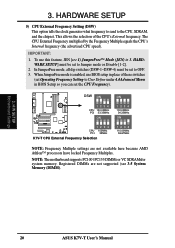
... processors have locked Frequency Multiples. 3. In JumperFree mode, all dip switches (DSW-1-DSW-4) must be set to OFF. 3. NOTE: The motherboard supports PC100 / PC133 DIMMs or VC SDRAMsfor system memory. HARDWARE SETUP] must be set to Jumper mode or Disable [1-2]. 2. When JumperFree ...mode is enabled, use this feature, JEN [see 3.5 System Memory (DIMM). 3. H/W SETUP Motherboard Settings 20 ASUS K7V-T User's Manual This allows the selection of these switches (set Operating Frequency Setting to the CPU, SDRAM, and the chipset.
... processors have locked Frequency Multiples. 3. In JumperFree mode, all dip switches (DSW-1-DSW-4) must be set to OFF. 3. NOTE: The motherboard supports PC100 / PC133 DIMMs or VC SDRAMsfor system memory. HARDWARE SETUP] must be set to Jumper mode or Disable [1-2]. 2. When JumperFree ...mode is enabled, use this feature, JEN [see 3.5 System Memory (DIMM). 3. H/W SETUP Motherboard Settings 20 ASUS K7V-T User's Manual This allows the selection of these switches (set Operating Frequency Setting to the CPU, SDRAM, and the chipset.

K7V-T User Manual
Page 21
...OFF] [OFF] [ON] [OFF] [OFF] [OFF] [ON] [OFF] [ON] NOTE: For updated processor settings, visit the ASUS web site (see ASUS CONTACT INFORMATION). WARNING! Be sure that the DIMM you use CPU Default as the CPU core voltage. CPU Default means the Vcore is recommended... 1.7/1.75Volts 1.6/1.65Volts 1.5/1.55Volts 1234 VID3 1234 1234 VID2 VID1 1.4/1.45Volts 1.3/1.35olts CPU Default/ JumperFree (Default) ASUS K7V-T User's Manual 21 H/W SETUP Motherboard Settings 3. Premature wearing of the processor may result when overclocking. It is generated according to manually adjust the...
...OFF] [OFF] [ON] [OFF] [OFF] [OFF] [ON] [OFF] [ON] NOTE: For updated processor settings, visit the ASUS web site (see ASUS CONTACT INFORMATION). WARNING! Be sure that the DIMM you use CPU Default as the CPU core voltage. CPU Default means the Vcore is recommended... 1.7/1.75Volts 1.6/1.65Volts 1.5/1.55Volts 1234 VID3 1234 1234 VID2 VID1 1.4/1.45Volts 1.3/1.35olts CPU Default/ JumperFree (Default) ASUS K7V-T User's Manual 21 H/W SETUP Motherboard Settings 3. Premature wearing of the processor may result when overclocking. It is generated according to manually adjust the...

K7V-T User Manual
Page 22
..., 256, 512MB SDRAM 16, 32, 64, 128, 256, 512MB Total System Memory (Max 768B) Total Memory x1 x1 x1 = 3.5.1 General DIMM Notes • This motherboard supports SPD (Serial Presence Detect) DIMMs. This is the memory of the DIMM takes up one row on bootup screen. • Single-sided DIMMs come... in 32, 64, 128, 256, 512MB. 22 ASUS K7V-T User's Manual Memory speed setup is required after adding or removing memory. H/W SETUP System Memory 3. to mix SDRAMs with 9 chips per side (standard 8 ...
..., 256, 512MB SDRAM 16, 32, 64, 128, 256, 512MB Total System Memory (Max 768B) Total Memory x1 x1 x1 = 3.5.1 General DIMM Notes • This motherboard supports SPD (Serial Presence Detect) DIMMs. This is the memory of the DIMM takes up one row on bootup screen. • Single-sided DIMMs come... in 32, 64, 128, 256, 512MB. 22 ASUS K7V-T User's Manual Memory speed setup is required after adding or removing memory. H/W SETUP System Memory 3. to mix SDRAMs with 9 chips per side (standard 8 ...

K7V-T User Manual
Page 23
...pin density. You must be 3.3V Unbuffered for this motherboard. To determine the DIMM type, check the notches on both sides. 3. HARDWARE SETUP 3.5.2 DIMM Memory Installation Insert the module(s) as shown. Lock 88 Pins 01 01 01 K7V-T ® K7V-T 168-Pin DIMM Sockets 60 Pins 20 Pins The... orientation shown. H/W SETUP System Memory DRAM Key Position RFU Unbuffered Buffered Voltage Key Position 5.0V Reserved 3.3V The notches on the motherboard. Because the number of pins are longer and have different pin contact on each side and therefore have the same pin contact on...
...pin density. You must be 3.3V Unbuffered for this motherboard. To determine the DIMM type, check the notches on both sides. 3. HARDWARE SETUP 3.5.2 DIMM Memory Installation Insert the module(s) as shown. Lock 88 Pins 01 01 01 K7V-T ® K7V-T 168-Pin DIMM Sockets 60 Pins 20 Pins The... orientation shown. H/W SETUP System Memory DRAM Key Position RFU Unbuffered Buffered Voltage Key Position 5.0V Reserved 3.3V The notches on the motherboard. Because the number of pins are longer and have different pin contact on each side and therefore have the same pin contact on...

K7V-T User Manual
Page 25
... CPU Installation Procedure 1. H/W SETUP CPU ASUS K7V-T User's Manual 25 WARNING! Be sure that can be different from the following pictures are those with three-pin fans that there is working. Insert the processor. 3. Your K7 Series motherboard provides a Slot A connector for reference ...retention clip. Without sufficient circulation, the processor could overheat and damage both the processor and the motherboard. Install the Universal Retention Mechanism onto the motherboard. 3. Attach the heatsink to the fan connectors on recommended heatsinks for your CPU fan is...
... CPU Installation Procedure 1. H/W SETUP CPU ASUS K7V-T User's Manual 25 WARNING! Be sure that can be different from the following pictures are those with three-pin fans that there is working. Insert the processor. 3. Your K7 Series motherboard provides a Slot A connector for reference ...retention clip. Without sufficient circulation, the processor could overheat and damage both the processor and the motherboard. Install the Universal Retention Mechanism onto the motherboard. 3. Attach the heatsink to the fan connectors on recommended heatsinks for your CPU fan is...


