
User Guide
Page 2
... FROM ANY DEFECT OR ERROR IN THIS MANUAL OR PRODUCT. SPECIFICATIONS AND INFORMATION CONTAINED IN THIS MANUAL ARE FURNISHED FOR INFORMATIONAL USE ONLY, AND ARE SUBJECT TO CHANGE AT ANY TIME WITHOUT NOTICE, AND SHOULD NOT BE CONSTRUED AS A COMMITMENT BY ASUS. Such software in this manual may or may obtain it from http://support.asus.com/download or (2) for which is...
... FROM ANY DEFECT OR ERROR IN THIS MANUAL OR PRODUCT. SPECIFICATIONS AND INFORMATION CONTAINED IN THIS MANUAL ARE FURNISHED FOR INFORMATIONAL USE ONLY, AND ARE SUBJECT TO CHANGE AT ANY TIME WITHOUT NOTICE, AND SHOULD NOT BE CONSTRUED AS A COMMITMENT BY ASUS. Such software in this manual may or may obtain it from http://support.asus.com/download or (2) for which is...
User Guide
Page 4
... discusses changing system settings through the BIOS Setup menus. These devices could interrupt the grounding circuit. • Ensure that the power cables for the devices are unplugged before the signal cables are connected. How this guide This user guide contains the information you are not damaged. iv If you need when installing and configuring the motherboard. If you encounter technical problems with the package. • Before using an...
... discusses changing system settings through the BIOS Setup menus. These devices could interrupt the grounding circuit. • Ensure that the power cables for the devices are unplugged before the signal cables are connected. How this guide This user guide contains the information you are not damaged. iv If you need when installing and configuring the motherboard. If you encounter technical problems with the package. • Before using an...
User Guide
Page 6
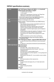
...memory Dual-channel memory architecture Supports Intel® Extreme Memory Profile (XMP) * Due to Intel® chipset limitation, DDR3 1600 MHz and higher memory modules on XMP mode will run at x16 mode) 3 x PCI Express 2.0 x1 slots Integrated Graphics Processor - Package contents Check your motherboard package for the following items. Motherboard Cables Accessories Application DVD Documentation ASUS H97M-E motherboard 2 x Serial ATA 6.0 Gb/s cables 1 x I/O Shield Support DVD User Guide If any of 1920 x 1200 @60Hz Supports RGB with max. H97M-E specifications summary CPU Chipset Memory...
...memory Dual-channel memory architecture Supports Intel® Extreme Memory Profile (XMP) * Due to Intel® chipset limitation, DDR3 1600 MHz and higher memory modules on XMP mode will run at x16 mode) 3 x PCI Express 2.0 x1 slots Integrated Graphics Processor - Package contents Check your motherboard package for the following items. Motherboard Cables Accessories Application DVD Documentation ASUS H97M-E motherboard 2 x Serial ATA 6.0 Gb/s cables 1 x I/O Shield Support DVD User Guide If any of 1920 x 1200 @60Hz Supports RGB with max. H97M-E specifications summary CPU Chipset Memory...
User Guide
Page 7
... CPU installed. Dedicated audio PCB layers: Separate layers for headphone and speakers - Audio amplifier: Provides the highest-quality sound for left and right channels to 10 Gb/s data transfer speeds ASUS Fan Xpert 2+ - Short circuit damage prevention - ASUS ESD Guards - Supports Intel® Smart Response Technology, Intel® Rapid Start Technology, and Intel® Smart Connect Technology* * The M.2 Socket 3 supports M Key and type 2260/2280 storage devices. * These functions will work depending on the next page) vii supports ASUS USB...
... CPU installed. Dedicated audio PCB layers: Separate layers for headphone and speakers - Audio amplifier: Provides the highest-quality sound for left and right channels to 10 Gb/s data transfer speeds ASUS Fan Xpert 2+ - Short circuit damage prevention - ASUS ESD Guards - Supports Intel® Smart Response Technology, Intel® Rapid Start Technology, and Intel® Smart Connect Technology* * The M.2 Socket 3 supports M Key and type 2260/2280 storage devices. * These functions will work depending on the next page) vii supports ASUS USB...

User Guide
Page 9
... 6 USB ports 4 x SATA 6.0 Gb/s connectors (gray) 1 x M.2 socket 3 (for M Key, type 2260/2280 devices) 1 x 4-pin CPU Fan connector (PWM mode) 2 x 4-pin Chassis Fan connectors for 3-pin (DC mode) and 4-pin (PWM mode) coolers control 1 x Front panel audio connector (AAFP) 1 x System panel connector 1 x Speaker connector 1 x S/PDIF out header 1 x Chassis intrusion connector 1 x 24-pin EATX Power connector 1 x 8-pin EATX 12V Power connector 1 x COM connector 1 x TPM connector 1 x Chassis intrusion connector 1 x Clear CMOS jumper 64 Mb Flash ROM, UEFI AMI BIOS, PnP, DMI2.7, WfM2.0, SM BIOS 2.8, ACPI...
... 6 USB ports 4 x SATA 6.0 Gb/s connectors (gray) 1 x M.2 socket 3 (for M Key, type 2260/2280 devices) 1 x 4-pin CPU Fan connector (PWM mode) 2 x 4-pin Chassis Fan connectors for 3-pin (DC mode) and 4-pin (PWM mode) coolers control 1 x Front panel audio connector (AAFP) 1 x System panel connector 1 x Speaker connector 1 x S/PDIF out header 1 x Chassis intrusion connector 1 x 24-pin EATX Power connector 1 x 8-pin EATX 12V Power connector 1 x COM connector 1 x TPM connector 1 x Chassis intrusion connector 1 x Clear CMOS jumper 64 Mb Flash ROM, UEFI AMI BIOS, PnP, DMI2.7, WfM2.0, SM BIOS 2.8, ACPI...

User Guide
Page 11
Failure to do so may cause severe damage to the motherboard, peripherals, or components. 1.2 Motherboard overview Before you install the motherboard, study the configuration of your chassis to ensure that the ATX power supply is switched off or the power cord is detached from the wall socket before touching any component. • Before handling components, use a grounded wrist strap or touch a safely grounded object or a metal...
Failure to do so may cause severe damage to the motherboard, peripherals, or components. 1.2 Motherboard overview Before you install the motherboard, study the configuration of your chassis to ensure that the ATX power supply is switched off or the power cord is detached from the wall socket before touching any component. • Before handling components, use a grounded wrist strap or touch a safely grounded object or a metal...
User Guide
Page 13
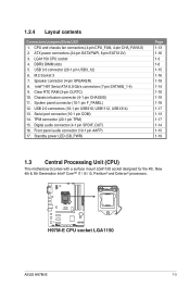
...Unit (CPU) This motherboard comes with a surface mount LGA1150 socket designed for the 4th, New 4th & 5th Generation Intel® Core™ i7 / i5 / i3, Pentium® and Celeron® processors. Intel® H97 Serial ATA 6.0 Gb/s connectors (7-pin SATA6G_1-4) 9. 1.2.4 Layout contents Connectors/Jumpers/Slots/LED 1. Digital audio connector (4-1 pin SPDIF_OUT) 16. USB 3.0 connector (20-1 pin USB3_12) 6. Clear RTC RAM (3-pin CLRTC) 10. Front panel audio connector (10-1 pin AAFP) 17. CPU and chassis fan connectors (4-pin CPU_FAN, 4-pin CHA_FAN1/2) 2. Chassis intrusion connector (4-1 pin...
...Unit (CPU) This motherboard comes with a surface mount LGA1150 socket designed for the 4th, New 4th & 5th Generation Intel® Core™ i7 / i5 / i3, Pentium® and Celeron® processors. Intel® H97 Serial ATA 6.0 Gb/s connectors (7-pin SATA6G_1-4) 9. 1.2.4 Layout contents Connectors/Jumpers/Slots/LED 1. Digital audio connector (4-1 pin SPDIF_OUT) 16. USB 3.0 connector (20-1 pin USB3_12) 6. Clear RTC RAM (3-pin CLRTC) 10. Front panel audio connector (10-1 pin AAFP) 17. CPU and chassis fan connectors (4-pin CPU_FAN, 4-pin CHA_FAN1/2) 2. Chassis intrusion connector (4-1 pin...
User Guide
Page 17
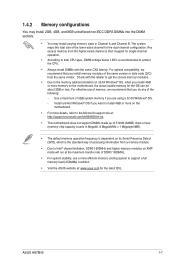
... effective use a more efficient memory cooling system to support a full memory load (4 DIMMs) condition. • Visit the ASUS website at: www.asus.com for the dual-channel configuration. 1.4.2 Memory configurations You may install 2GB, 4GB, and 8GB unbuffered non-ECC DDR3 DIMMs into the DIMM sockets. • You may install varying memory sizes in Megabit, 8 Megabit/Mb = 1 Megabyte/MB). • The default memory operation frequency is dependent on its Serial Presence...
... effective use a more efficient memory cooling system to support a full memory load (4 DIMMs) condition. • Visit the ASUS website at: www.asus.com for the dual-channel configuration. 1.4.2 Memory configurations You may install 2GB, 4GB, and 8GB unbuffered non-ECC DDR3 DIMMs into the DIMM sockets. • You may install varying memory sizes in Megabit, 8 Megabit/Mb = 1 Megabyte/MB). • The default memory operation frequency is dependent on its Serial Presence...

User Guide
Page 19
... they support. See Chapter 2 for the card. 2. ASUS H97M-E 1-9 Secure the card to the card. 3. Keep the screw for the expansion card. Turn on BIOS setup. 2. Install the software drivers for later use . Unplug the power cord before adding or removing expansion cards. Assign an IRQ to the chassis with it by adjusting the software settings. 1. Remove the bracket opposite the slot that came with the screw you removed earlier. 6. Replace the system cover. 1.5.2 Configuring...
... they support. See Chapter 2 for the card. 2. ASUS H97M-E 1-9 Secure the card to the card. 3. Keep the screw for the expansion card. Turn on BIOS setup. 2. Install the software drivers for later use . Unplug the power cord before adding or removing expansion cards. Assign an IRQ to the chassis with it by adjusting the software settings. 1. Remove the bracket opposite the slot that came with the screw you removed earlier. 6. Replace the system cover. 1.5.2 Configuring...
User Guide
Page 20
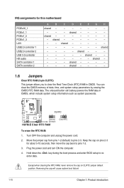
...can clear the CMOS memory of date, time, and system setup parameters by erasing the CMOS RTC RAM data. Turn OFF the computer and unplug the power cord. 2. Except when clearing the RTC RAM, never remove the cap on pins 2-3 for this motherboard PCIEx16_1 PCIEx1_1 PCIEx1_2 PCIEx1_3 LAN USB2.0 controller 1 USB2.0 controller 2 USB 3.0 controller HD audio SATA controller 1 SATA controller 2 A B C D EFG H shared - - - - - - - - - - shared - - - - - - - shared - - - - 1.6 Jumpers Clear RTC RAM (3-pin CLRTC) This jumper allows you to pins 2-3. Move the jumper cap...
...can clear the CMOS memory of date, time, and system setup parameters by erasing the CMOS RTC RAM data. Turn OFF the computer and unplug the power cord. 2. Except when clearing the RTC RAM, never remove the cap on pins 2-3 for this motherboard PCIEx16_1 PCIEx1_1 PCIEx1_2 PCIEx1_3 LAN USB2.0 controller 1 USB2.0 controller 2 USB 3.0 controller HD audio SATA controller 1 SATA controller 2 A B C D EFG H shared - - - - - - - - - - shared - - - - - - - shared - - - - 1.6 Jumpers Clear RTC RAM (3-pin CLRTC) This jumper allows you to pins 2-3. Move the jumper cap...
User Guide
Page 21
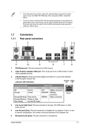
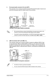
... Speaker Out. 6. LAN (RJ-45) port. Microphone port (pink). After clearing the CMOS, reinstall the battery. • You do not help, remove the onboard battery and move the jumper again to clear the CMOS RTC RAM data. This port connects to a PS/2 mouse. 2. ASUS H97M-E 1-11 Line In port (light blue). This port connects to a headphone or a speaker. This 15-pin port is for a VGA monitor or other audio sources. 5. This port connects to the tape, CD, DVD player, or other VGA-compatible devices...
... Speaker Out. 6. LAN (RJ-45) port. Microphone port (pink). After clearing the CMOS, reinstall the battery. • You do not help, remove the onboard battery and move the jumper again to clear the CMOS RTC RAM data. This port connects to a PS/2 mouse. 2. ASUS H97M-E 1-11 Line In port (light blue). This port connects to a headphone or a speaker. This 15-pin port is for a VGA monitor or other audio sources. 5. This port connects to the tape, CD, DVD player, or other VGA-compatible devices...
User Guide
Page 25
... connect a high-definition or an AC'97 front panel audio module to this connector, set the Front Panel Type item in the BIOS setup to connect a USB 3.0 module for additional USB 3.0 front or rear panel ports. USB 3.0 connector (20-1 pin USB3_12) This connector allows you can connect the ASUS front panel USB 3.0 bracket to 5Gbps, faster charging time for a chassis-mounted front panel HD audio I /O module cable to this connector. With an installed USB 3.0 module, you to [HD] or [AC97]. 6. H97M...
... connect a high-definition or an AC'97 front panel audio module to this connector, set the Front Panel Type item in the BIOS setup to connect a USB 3.0 module for additional USB 3.0 front or rear panel ports. USB 3.0 connector (20-1 pin USB3_12) This connector allows you can connect the ASUS front panel USB 3.0 bracket to 5Gbps, faster charging time for a chassis-mounted front panel HD audio I /O module cable to this connector. With an installed USB 3.0 module, you to [HD] or [AC97]. 6. H97M...
User Guide
Page 27
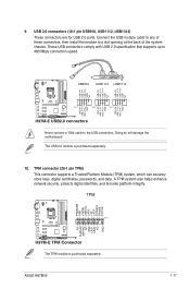
..., and ensures platform integrity. The USB 2.0 module is purchased separately. ASUS H97M-E 1-17 9. USB 2.0 connectors (10-1 pin USB910, USB1112, USB1314) These connectors are for USB 2.0 ports. Connect the USB module cable to any of the system chassis. TPM connector (20-1 pin TPM) This connector supports a Trusted Platform Module (TPM) system, which can securely store keys, digital certificates, passwords, and data. Doing so will damage the motherboard! TPM PWRDWN GND +3VSB...
..., and ensures platform integrity. The USB 2.0 module is purchased separately. ASUS H97M-E 1-17 9. USB 2.0 connectors (10-1 pin USB910, USB1112, USB1314) These connectors are for USB 2.0 ports. Connect the USB module cable to any of the system chassis. TPM connector (20-1 pin TPM) This connector supports a Trusted Platform Module (TPM) system, which can securely store keys, digital certificates, passwords, and data. Doing so will damage the motherboard! TPM PWRDWN GND +3VSB...

User Guide
Page 30
... to display Support DVD/motherboard information Click an item to install If Autorun is NOT enabled in your hardware. Always install the latest OS version and corresponding updates to locate the file ASSETUP.EXE from the BIN folder. Visit the ASUS website at any time without notice. Refer to run the Support DVD Place the Support DVD into the optical drive. Click Drivers, Utilities, AHCI/RAID Driver, Manual, Contact, and Specials tabs to change...
... to display Support DVD/motherboard information Click an item to install If Autorun is NOT enabled in your hardware. Always install the latest OS version and corresponding updates to locate the file ASSETUP.EXE from the BIN folder. Visit the ASUS website at any time without notice. Refer to run the Support DVD Place the Support DVD into the optical drive. Click Drivers, Utilities, AHCI/RAID Driver, Manual, Contact, and Specials tabs to change...
User Guide
Page 31
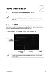
... original motherboard BIOS file to a USB flash disk in case you need to restore the BIOS in the future. Copy the original motherboard BIOS using the ASUS Update utility. 2.1.1 EZ Update EZ Update is a utility that allows you can also manually update the saved BIOS and select a boot logo when the system goes into POST. With this utlity, you to automatically update your motherboard's softwares, drivers and the BIOS version easily. ASUS H97M-E 2-1 BIOS information 2.1 Managing and updating your motherboard's driver, software and firmware Model Name: H97M-E Version: 0301...
... original motherboard BIOS file to a USB flash disk in case you need to restore the BIOS in the future. Copy the original motherboard BIOS using the ASUS Update utility. 2.1.1 EZ Update EZ Update is a utility that allows you can also manually update the saved BIOS and select a boot logo when the system goes into POST. With this utlity, you to automatically update your motherboard's softwares, drivers and the BIOS version easily. ASUS H97M-E 2-1 BIOS information 2.1 Managing and updating your motherboard's driver, software and firmware Model Name: H97M-E Version: 0301...

User Guide
Page 32
... motherboard support DVD or a USB flash drive that allows you start using this utility, download the latest BIOS file from the ASUS website at www.asus.com. To update the BIOS using an OS‑based utility. Press the Up/Down arrow keys to find the USB flash disk that contains the latest BIOS file to prevent system boot failure! 2.1.3 ASUS CrashFree BIOS 3 utility The ASUS CrashFree BIOS 3 is an auto recovery tool that contains the updated BIOS file. • Before using this utility, rename the BIOS file in the removable device...
... motherboard support DVD or a USB flash drive that allows you start using this utility, download the latest BIOS file from the ASUS website at www.asus.com. To update the BIOS using an OS‑based utility. Press the Up/Down arrow keys to find the USB flash disk that contains the latest BIOS file to prevent system boot failure! 2.1.3 ASUS CrashFree BIOS 3 utility The ASUS CrashFree BIOS 3 is an auto recovery tool that contains the updated BIOS file. • Before using this utility, rename the BIOS file in the removable device...
User Guide
Page 33
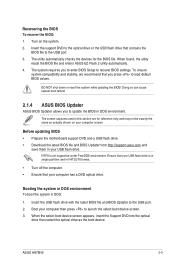
... cause system boot failure! 2.1.4 ASUS BIOS Updater ASUS BIOS Updater allows you to recover BIOS settings. Before updating BIOS • Prepare the motherboard support DVD and a USB flash drive. • Download the latest BIOS file and BIOS Updater from http://support.asus.com and save them in DOS environment. Insert the support DVD to the optical drive or the USB flash drive that you to enter BIOS Setup to update the BIOS in your USB flash drive. Ensure that your USB flash drive is not supported under FreeDOS environment. The screen captures used in this...
... cause system boot failure! 2.1.4 ASUS BIOS Updater ASUS BIOS Updater allows you to recover BIOS settings. Before updating BIOS • Prepare the motherboard support DVD and a USB flash drive. • Download the latest BIOS file and BIOS Updater from http://support.asus.com and save them in DOS environment. Insert the support DVD to the optical drive or the USB flash drive that you to enter BIOS Setup to update the BIOS in your USB flash drive. Ensure that your USB flash drive is not supported under FreeDOS environment. The screen captures used in this...
User Guide
Page 36
... the system fails to boot after changing any BIOS setting, load the default settings to ensure system compatibility and stability. Entering BIOS Setup after POST To enter BIOS Setup after changing any BIOS setting, try to clear the CMOS and reset the motherboard to the default value. Using the power button, reset button, or the ++ keys to force reset from the operating system. • The BIOS setup screens shown in using the first two options. BIOS menu screen The BIOS setup program can cause damage to turn the system off then...
... the system fails to boot after changing any BIOS setting, load the default settings to ensure system compatibility and stability. Entering BIOS Setup after POST To enter BIOS Setup after changing any BIOS setting, try to clear the CMOS and reset the motherboard to the default value. Using the power button, reset button, or the ++ keys to force reset from the operating system. • The BIOS setup screens shown in using the first two options. BIOS menu screen The BIOS setup program can cause damage to turn the system off then...
User Guide
Page 37
... options for entering the BIOS setup program can be changed. Displays the system information, CPU voltage and CPU/ motherboard temperature Sets the system date and time Selects the display language of the Advanced Mode. status IRST support setting Loads optimized default Displays the CPU/ chassis fan speed Save changes and exit the BIOS setup program Displays the Advanced mode menus • The boot device options vary depending on the devices you to configure the BIOS settings. Refer to the Setup Mode item in section 2.8 Boot menu for the detailed configurations...
... options for entering the BIOS setup program can be changed. Displays the system information, CPU voltage and CPU/ motherboard temperature Sets the system date and time Selects the display language of the Advanced Mode. status IRST support setting Loads optimized default Displays the CPU/ chassis fan speed Save changes and exit the BIOS setup program Displays the Advanced mode menus • The boot device options vary depending on the devices you to configure the BIOS settings. Refer to the Setup Mode item in section 2.8 Boot menu for the detailed configurations...

User Guide
Page 39
... a submenu. ASUS H97M-E 2-9 For example, selecting Main shows the Main menu items. The other items on the screen. Press or use the USB mouse to click this button to return to select items in English. If you can change the settings. A configurable field is a brief description of the menu screen is highlighted when selected. Menu items The highlighted item on the menu bar displays the specific items for...
... a submenu. ASUS H97M-E 2-9 For example, selecting Main shows the Main menu items. The other items on the screen. Press or use the USB mouse to click this button to return to select items in English. If you can change the settings. A configurable field is a brief description of the menu screen is highlighted when selected. Menu items The highlighted item on the menu bar displays the specific items for...


