
H81I-PLUS User's Manual
Page 1
H81I-PLUS Motherboard
H81I-PLUS Motherboard
H81I-PLUS User's Manual
Page 3
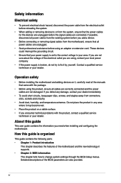
Contents Safety information...iv About this guide...iv Package contents...vi H81I-PLUS specifications summary vi Product introduction 1.1 Before you proceed 1-1 1.2 Motherboard overview 1-1 1.3 Central Processing Unit (CPU 1-3 1.4 System memory 1-6 1.5 Expansion slots 1-8 1.6 Jumpers...1-10 1.7 Connectors 1-11 1.8 Onboard LEDs 1-18 1.9 Software support 1-19 BIOS information 2.1 Managing ... 2-11 2.5 Ai Tweaker menu 2-13 2.6 Advanced menu 2-24 2.7 Monitor menu 2-32 2.8 Boot menu 2-35 2.9 Tools menu 2-41 2.10 Exit menu...2-42 Appendices Notices...A-1 ASUS contact information A-3 iii
Contents Safety information...iv About this guide...iv Package contents...vi H81I-PLUS specifications summary vi Product introduction 1.1 Before you proceed 1-1 1.2 Motherboard overview 1-1 1.3 Central Processing Unit (CPU 1-3 1.4 System memory 1-6 1.5 Expansion slots 1-8 1.6 Jumpers...1-10 1.7 Connectors 1-11 1.8 Onboard LEDs 1-18 1.9 Software support 1-19 BIOS information 2.1 Managing ... 2-11 2.5 Ai Tweaker menu 2-13 2.6 Advanced menu 2-24 2.7 Monitor menu 2-32 2.8 Boot menu 2-35 2.9 Tools menu 2-41 2.10 Exit menu...2-42 Appendices Notices...A-1 ASUS contact information A-3 iii
H81I-PLUS User's Manual
Page 4
...technician or your retailer. If you are not sure about the voltage of the electrical outlet you need when installing and configuring the motherboard. iv How this guide This user guide contains the information you are also provided. Contact a qualified service technician or your dealer ... are unplugged. • Seek professional assistance before using the product, ensure all power cables are connected. Detailed descriptions of the motherboard and the new technology it , carefully read all the manuals that all cables are correctly connected and the power cables are not...
...technician or your retailer. If you are not sure about the voltage of the electrical outlet you need when installing and configuring the motherboard. iv How this guide This user guide contains the information you are also provided. Contact a qualified service technician or your dealer ... are unplugged. • Seek professional assistance before using the product, ensure all power cables are connected. Detailed descriptions of the motherboard and the new technology it , carefully read all the manuals that all cables are correctly connected and the power cables are not...
H81I-PLUS User's Manual
Page 6
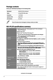
... modules on XMP mode will update the memory QVL once the DIMMs are available in the front panel to www.asus.com for the following items. Motherboard Cables Accessories Application DVD Documentation ASUS H81I-PLUS motherboard 2 x Serial ATA 6.0 Gb/s cables 1 x I/O Shield Support DVD User Guide If any of DDR3 1600MHz. resolution 4096 x 2304@24Hz / 2560x1600@60Hz...
... modules on XMP mode will update the memory QVL once the DIMMs are available in the front panel to www.asus.com for the following items. Motherboard Cables Accessories Application DVD Documentation ASUS H81I-PLUS motherboard 2 x Serial ATA 6.0 Gb/s cables 1 x I/O Shield Support DVD User Guide If any of DDR3 1600MHz. resolution 4096 x 2304@24Hz / 2560x1600@60Hz...
H81I-PLUS User's Manual
Page 9
... or the power cord is detached from the wall socket before installing or removing the motherboard. Do not overtighten the screws! ASUS H81I-PLUS 1-1 Failure to do so may cause severe damage to the motherboard, peripherals, or components. 1.2 Motherboard overview Before you install the motherboard, study the configuration of your chassis to do so can damage the...
... or the power cord is detached from the wall socket before installing or removing the motherboard. Do not overtighten the screws! ASUS H81I-PLUS 1-1 Failure to do so may cause severe damage to the motherboard, peripherals, or components. 1.2 Motherboard overview Before you install the motherboard, study the configuration of your chassis to do so can damage the...
H81I-PLUS User's Manual
Page 10
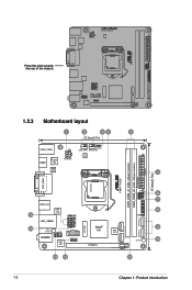
... side towards the rear of the chassis 1.2.3 Motherboard layout 1 2 34 5 17.0cm(6.7in) KBMS_USB56 HDMI Super I/O ATX12V CLRTC CHA_FAN CPU_FAN DIGI +VRM ASM 1042 1 17.0cm(6.7in) EATXPWR DDR3_DIMM_B1 (64bit, 240-pin module) DDR3_DIMM_A1 (64bit, 240-pin module) H81I-PLUS DVI_VGA LGA1150 F_PANEL USB3_E12 ASM 1042 15 USB1112 LAN_USB34 BATTERY 14 RTL 8111GR...
... side towards the rear of the chassis 1.2.3 Motherboard layout 1 2 34 5 17.0cm(6.7in) KBMS_USB56 HDMI Super I/O ATX12V CLRTC CHA_FAN CPU_FAN DIGI +VRM ASM 1042 1 17.0cm(6.7in) EATXPWR DDR3_DIMM_B1 (64bit, 240-pin module) DDR3_DIMM_A1 (64bit, 240-pin module) H81I-PLUS DVI_VGA LGA1150 F_PANEL USB3_E12 ASM 1042 15 USB1112 LAN_USB34 BATTERY 14 RTL 8111GR...
H81I-PLUS User's Manual
Page 11
...installation/removal, or misplacement/loss/incorrect removal of the motherboard, ensure that you see any damage to the PnP cap/socket contacts/motherboard components. TPM connector (20-1 pin TPM) 9. H81I-PLUS H81I-PLUS CPU socket LGA1150 Unplug all power cables before installing...installing the motherboard. DDR3 DIMM slots 6. Onboard LED (SB_PWR) 11. 1.2.4 Layout contents Connectors/Jumpers/Slots/LED 1. DO NOT install a CPU designed for LGA 1150 only. Clear RTC RAM (3-pin CLRTC) 4. ATX power connectors (24-pin EATXPWR, 4-pin ATX12V) 2. ASUS H81I-PLUS 1-3 Intel...
...installation/removal, or misplacement/loss/incorrect removal of the motherboard, ensure that you see any damage to the PnP cap/socket contacts/motherboard components. TPM connector (20-1 pin TPM) 9. H81I-PLUS H81I-PLUS CPU socket LGA1150 Unplug all power cables before installing...installing the motherboard. DDR3 DIMM slots 6. Onboard LED (SB_PWR) 11. 1.2.4 Layout contents Connectors/Jumpers/Slots/LED 1. DO NOT install a CPU designed for LGA 1150 only. Clear RTC RAM (3-pin CLRTC) 4. ATX power connectors (24-pin EATXPWR, 4-pin ATX12V) 2. ASUS H81I-PLUS 1-3 Intel...
H81I-PLUS User's Manual
Page 14
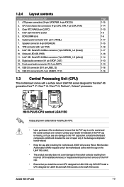
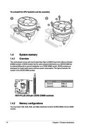
The figure illustrates the location of the DDR3 DIMM sockets: H81I-PLUS DIMM_A1 DIMM_B1 Channel Channel A Channel B Sockets DIMM_A1 DIMM_B1 H81I-PLUS 240-pin DDR3 DIMM sockets 1.4.2 Memory configurations You may install 1GB, 2GB, 4GB, and 8GB unbuffered non‑ECC DDR3 DIMMs into the DIMM sockets. 1-6 ... a DDR2 DIMM but is notched differently to prevent installation on a DDR2 DIMM socket. To uninstall the CPU heatsink and fan assembly 1 2 B A B A 1.4 System memory 1.4.1 Overview This motherboard comes with less power consumption.
The figure illustrates the location of the DDR3 DIMM sockets: H81I-PLUS DIMM_A1 DIMM_B1 Channel Channel A Channel B Sockets DIMM_A1 DIMM_B1 H81I-PLUS 240-pin DDR3 DIMM sockets 1.4.2 Memory configurations You may install 1GB, 2GB, 4GB, and 8GB unbuffered non‑ECC DDR3 DIMMs into the DIMM sockets. 1-6 ... a DDR2 DIMM but is notched differently to prevent installation on a DDR2 DIMM socket. To uninstall the CPU heatsink and fan assembly 1 2 B A B A 1.4 System memory 1.4.1 Overview This motherboard comes with less power consumption.
H81I-PLUS User's Manual
Page 15
...Mb) chips or less. • Memory modules with the retailer to get the correct memory modules. • Due to both the motherboard and the components. 1. ASUS H81I-PLUS 1-7 The system maps the total size of memory, we recommend that you do so can be about 3GB or less. Use a ...maximum of accessing information from a memory module. For effective use a more memory on the motherboard, the actual usable memory for the dual-channel...
...Mb) chips or less. • Memory modules with the retailer to get the correct memory modules. • Due to both the motherboard and the components. 1. ASUS H81I-PLUS 1-7 The system maps the total size of memory, we recommend that you do so can be about 3GB or less. Use a ...maximum of accessing information from a memory module. For effective use a more memory on the motherboard, the actual usable memory for the dual-channel...
H81I-PLUS User's Manual
Page 16
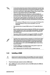
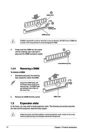
Firmly insert the DIMM into a socket in only one direction. DIMM notch 1.5 Expansion slots In the future, you may cause you physical injury and damage motherboard components. 1-8 Chapter 1: Product introduction The DIMM might get damaged when it fits in the wrong direction to do so may need to unlock the DIMM. ...
Firmly insert the DIMM into a socket in only one direction. DIMM notch 1.5 Expansion slots In the future, you may cause you physical injury and damage motherboard components. 1-8 Chapter 1: Product introduction The DIMM might get damaged when it fits in the wrong direction to do so may need to unlock the DIMM. ...
H81I-PLUS User's Manual
Page 17
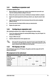
... unstable and the card inoperable. 1.5.3 PCI Express x16 slot This motherboard supports two PCI Express x16 graphics cards that came with the screw you removed earlier. 6. shared - - - - - - - - - ASUS H81I-PLUS 1-9 IRQ assignments for later use . Align the card connector with... card, read the documentation that comply with the slot and press firmly until the card is already installed in a chassis). 3. Keep the screw for this motherboard PCIe x16 Intel SATA Controller Realtek LAN Intel xHCI Intel EHCI 1 Intel EHCI 2 HD Audio A B C D E F G H shared - - -...
... unstable and the card inoperable. 1.5.3 PCI Express x16 slot This motherboard supports two PCI Express x16 graphics cards that came with the screw you removed earlier. 6. shared - - - - - - - - - ASUS H81I-PLUS 1-9 IRQ assignments for later use . Align the card connector with... card, read the documentation that comply with the slot and press firmly until the card is already installed in a chassis). 3. Keep the screw for this motherboard PCIe x16 Intel SATA Controller Realtek LAN Intel xHCI Intel EHCI 1 Intel EHCI 2 HD Audio A B C D E F G H shared - - -...
H81I-PLUS User's Manual
Page 21
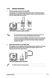
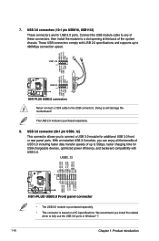
... a high-definition front panel audio module to this connector to avail of the motherboard's high-definition audio capability. • If you want to connect a high-definition front panel audio module to this connector, then install the module to [HD]. 2. ASUS H81I-PLUS 1-13 By default, this connector, set the Front Panel Type item in...
... a high-definition front panel audio module to this connector to avail of the motherboard's high-definition audio capability. • If you want to connect a high-definition front panel audio module to this connector, then install the module to [HD]. 2. ASUS H81I-PLUS 1-13 By default, this connector, set the Front Panel Type item in...

H81I-PLUS User's Manual
Page 22
H81I-PLUS 1-14 Chapter 1: Product introduction H81I-PLUS CPU FAN PWM CPU FAN IN CPU FAN PWR GND CHA FAN PWM CHA FAN IN CHA FAN PWR GND 3. Insufficient air flow inside the system may damage the motherboard components. Intel® H81 Serial ATA 6.0Gb/s connector (7-pin SATA6G_1~2 [... jumper caps on the motherboard, ensuring that the black wire of each cable matches the ground pin of maximum 1A (12 W) fan power. 4. SATA6G_1 GND RSATA_TXP1 RSATA_TXN1 GND RSATA_RXN1 RSATA_RXP1 GND SATA6G_2 GND RSATA_TXP2 RSATA_TXN2 GND RSATA_RXN2 RSATA_RXP2 GND H81I-PLUS SATA 6.0Gb/s connectors When...
H81I-PLUS 1-14 Chapter 1: Product introduction H81I-PLUS CPU FAN PWM CPU FAN IN CPU FAN PWR GND CHA FAN PWM CHA FAN IN CHA FAN PWR GND 3. Insufficient air flow inside the system may damage the motherboard components. Intel® H81 Serial ATA 6.0Gb/s connector (7-pin SATA6G_1~2 [... jumper caps on the motherboard, ensuring that the black wire of each cable matches the ground pin of maximum 1A (12 W) fan power. 4. SATA6G_1 GND RSATA_TXP1 RSATA_TXN1 GND RSATA_RXN1 RSATA_RXP1 GND SATA6G_2 GND RSATA_TXP2 RSATA_TXN2 GND RSATA_RXN2 RSATA_RXP2 GND H81I-PLUS SATA 6.0Gb/s connectors When...
H81I-PLUS User's Manual
Page 24
Doing so will damage the motherboard! With an installed USB 3.0 module, you install the related driver to fully use the USB 3.0 ports in Windows® 7. 1-16 Chapter 1: Product introduction We recommend ... panel ports. These USB connectors comply with USB 2.0. USB 3.0 connector (20-1 pin USB3_12) This connector allows you to the USB connectors. USB1112 PIN 1 USB910 PIN 1 H81I-PLUS USB2.0 connectors Never connect a 1394 cable to connect a USB 3.0 module for USB 2.0 ports. USB3_12 PIN 1 +5V USB3_RX_DN3 USB3_RX_DP3 GND USB3_TX_DN3 USB3_TX_DP3 GND S_USB_PN2_R S_USB_PP2_R GND...
Doing so will damage the motherboard! With an installed USB 3.0 module, you install the related driver to fully use the USB 3.0 ports in Windows® 7. 1-16 Chapter 1: Product introduction We recommend ... panel ports. These USB connectors comply with USB 2.0. USB 3.0 connector (20-1 pin USB3_12) This connector allows you to the USB connectors. USB1112 PIN 1 USB910 PIN 1 H81I-PLUS USB2.0 connectors Never connect a 1394 cable to connect a USB 3.0 module for USB 2.0 ports. USB3_12 PIN 1 +5V USB3_RX_DN3 USB3_RX_DP3 GND USB3_TX_DN3 USB3_TX_DP3 GND S_USB_PN2_R S_USB_PP2_R GND...
H81I-PLUS User's Manual
Page 26
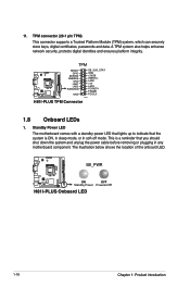
... SMBSDA GND LAD1 LAD2 PWROWN GND SB_SUS_STAT GND +3VSB SMBSCL LAD0 +3V LAD3 PCIRST# FRAME PCICLK PIN 1 H81I-PLUS TPM Connector 1.8 Onboard LEDs 1. Standby Power LED The motherboard comes with a standby power LED that lights up to indicate that the system is a reminder that you should... mode. The illustration below shows the location of the onboard LED. SB_PWR H81I-PLUS ON OFF Standby Power Powered Off H81I-PLUS Onboard LED 1-18 Chapter 1: Product introduction This is ON, in sleep mode, or in any motherboard component. 11. TPM connector (20-1 pin TPM) This connector supports a...
... SMBSDA GND LAD1 LAD2 PWROWN GND SB_SUS_STAT GND +3VSB SMBSCL LAD0 +3V LAD3 PCIRST# FRAME PCICLK PIN 1 H81I-PLUS TPM Connector 1.8 Onboard LEDs 1. Standby Power LED The motherboard comes with a standby power LED that lights up to indicate that the system is a reminder that you should... mode. The illustration below shows the location of the onboard LED. SB_PWR H81I-PLUS ON OFF Standby Power Powered Off H81I-PLUS Onboard LED 1-18 Chapter 1: Product introduction This is ON, in sleep mode, or in any motherboard component. 11. TPM connector (20-1 pin TPM) This connector supports a...
H81I-PLUS User's Manual
Page 27
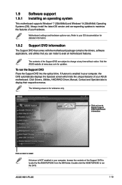
.... The following screen is enabled in your computer, browse the contents of your hardware. ASUS H81I-PLUS 1-19 Motherboard settings and hardware options vary. 1.9 Software support 1.9.1 Installing an operating system This motherboard supports Windows® 7 (32bit/64bit) and Windows® 8 (32bit/64bit) Operating Systems (OS). Click Drivers, Utilities, AHCI/RAID Driver, Manual, Contact and Specials...
.... The following screen is enabled in your computer, browse the contents of your hardware. ASUS H81I-PLUS 1-19 Motherboard settings and hardware options vary. 1.9 Software support 1.9.1 Installing an operating system This motherboard supports Windows® 7 (32bit/64bit) and Windows® 8 (32bit/64bit) Operating Systems (OS). Click Drivers, Utilities, AHCI/RAID Driver, Manual, Contact and Specials...
H81I-PLUS User's Manual
Page 29
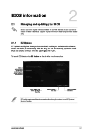
... the BIOS in case you to automatically update your motherboard's driver, software and firmware C:\Users\test\Downloads\H81I-PLUS-ASUS-02... Model Name: H81I-PLUS Version:0203 Release Date: 05/28/2013 File: H81I-PLUS-ASUS-0205.CAP Model Name: H81I-PLUS Version:0205 Release Date: 06/18/2013 Click to... find and select the BIOS from file Click to select a boot logo Click to automatically update your motherboard's softwares, drivers and the BIOS version easily. ASUS H81I-PLUS 2-1 Click to update the BIOS EZ Update requires an Internet connection either through a network or an ISP...
... the BIOS in case you to automatically update your motherboard's driver, software and firmware C:\Users\test\Downloads\H81I-PLUS-ASUS-02... Model Name: H81I-PLUS Version:0203 Release Date: 05/28/2013 File: H81I-PLUS-ASUS-0205.CAP Model Name: H81I-PLUS Version:0205 Release Date: 06/18/2013 Click to... find and select the BIOS from file Click to select a boot logo Click to automatically update your motherboard's softwares, drivers and the BIOS version easily. ASUS H81I-PLUS 2-1 Click to update the BIOS EZ Update requires an Internet connection either through a network or an ISP...
H81I-PLUS User's Manual
Page 31
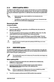
...the motherboard support DVD and a USB flash drive formatted using this utility, rename the BIOS file in the removable device into H81IPLUS.CAP. • The BIOS file in the support DVD may not be the latest version. Do not save them on the USB flash drive. ASUS H81I-PLUS ...2-3 The utility automatically checks the devices for reference only. 2.1.3 ASUS CrashFree BIOS 3 The ASUS CrashFree BIOS 3 is not supported under DOS environment. The succeeding utility screens are for the BIOS...
...the motherboard support DVD and a USB flash drive formatted using this utility, rename the BIOS file in the removable device into H81IPLUS.CAP. • The BIOS file in the support DVD may not be the latest version. Do not save them on the USB flash drive. ASUS H81I-PLUS ...2-3 The utility automatically checks the devices for reference only. 2.1.3 ASUS CrashFree BIOS 3 The ASUS CrashFree BIOS 3 is not supported under DOS environment. The succeeding utility screens are for the BIOS...
H81I-PLUS User's Manual
Page 34
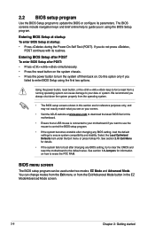
...system. See section 2.10 Exit Menu for reference purposes only, and may not exactly match what you see on your screen. • Visit the ASUS website at startup: • Press during the Power-On Self Test (POST). BIOS menu screen The BIOS setup program can cause damage to the ...default value. Entering BIOS Setup after POST To enter BIOS Setup after changing any BIOS setting, try to clear the CMOS and reset the motherboard to your motherboard if you in the EZ Mode/Advanced Mode screen. 2-6 Chapter 2: Getting started If you always shut down the system properly from the ...
...system. See section 2.10 Exit Menu for reference purposes only, and may not exactly match what you see on your screen. • Visit the ASUS website at startup: • Press during the Power-On Self Test (POST). BIOS menu screen The BIOS setup program can cause damage to the ...default value. Entering BIOS Setup after POST To enter BIOS Setup after changing any BIOS setting, try to clear the CMOS and reset the motherboard to your motherboard if you in the EZ Mode/Advanced Mode screen. 2-6 Chapter 2: Getting started If you always shut down the system properly from the ...
H81I-PLUS User's Manual
Page 35
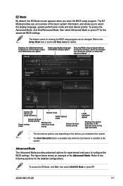
Refer to configure the BIOS settings. ASUS H81I-PLUS 2-7 The default screen for the advanced BIOS settings. Advanced Mode The Advanced Mode provides advanced options for experienced end-users to the following sections for ... is installed to the system. To access the EZ Mode, click Exit, then select ASUS EZ Mode or press F7. Refer to select the display language, system performance mode and boot device priority. Displays the CPU/motherboard temperature, CPU voltage output, and CPU/chassis fan speed Selects the display language of the...
Refer to configure the BIOS settings. ASUS H81I-PLUS 2-7 The default screen for the advanced BIOS settings. Advanced Mode The Advanced Mode provides advanced options for experienced end-users to the following sections for ... is installed to the system. To access the EZ Mode, click Exit, then select ASUS EZ Mode or press F7. Refer to select the display language, system performance mode and boot device priority. Displays the CPU/motherboard temperature, CPU voltage output, and CPU/chassis fan speed Selects the display language of the...


