Installation Guide
Page 5
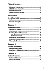
... Contents Disclaimer/Copyrights 2 ASUS Contact Information 3 FCC/CDC Statements 4 System Package Contents 6 Introduction About This Guide 7 Audience 8 Contents Description 8 Chapter 1 System Assembly 9 Opening the Chassis 10 Installing Disk Drives 11 Installing Optional Components 13 I/O Plate 13 PCI Expansion Card 13 Installing an IR-USB Module 14 Installing the Motherboard 15 Closing the...
... Contents Disclaimer/Copyrights 2 ASUS Contact Information 3 FCC/CDC Statements 4 System Package Contents 6 Introduction About This Guide 7 Audience 8 Contents Description 8 Chapter 1 System Assembly 9 Opening the Chassis 10 Installing Disk Drives 11 Installing Optional Components 13 I/O Plate 13 PCI Expansion Card 13 Installing an IR-USB Module 14 Installing the Motherboard 15 Closing the...

Installation Guide
Page 6
... included in the standard system package. 1) System Chassis 2) ASUS POLO Motherboard 3) Switching Power Supply 4) ASUS 24X CD-ROM Drive 5) CD-ROM Adapter Board 6) 1.44MB Floppy Disk Drive 7) IR-USB Module 8) PCI Riser Card 9) CPU Heatsink 10) Motherboard Support CD 11) CD-ROM Drive Support Disk 12) (1)... Cable 14) (1) Floppy Cable 15) (1) IR Cable (5-pin) 16) (1) USB Cable (10-pin) 17) ASUS Name Plate 18) Motherboard User's Manual 19) CD-ROM Drive Manual 20) Genie Book Size PC System Installation Guide Optional Components (not included in standard system package) 1) 56K PCI Modem Card 2) DFP...
... included in the standard system package. 1) System Chassis 2) ASUS POLO Motherboard 3) Switching Power Supply 4) ASUS 24X CD-ROM Drive 5) CD-ROM Adapter Board 6) 1.44MB Floppy Disk Drive 7) IR-USB Module 8) PCI Riser Card 9) CPU Heatsink 10) Motherboard Support CD 11) CD-ROM Drive Support Disk 12) (1)... Cable 14) (1) Floppy Cable 15) (1) IR Cable (5-pin) 16) (1) USB Cable (10-pin) 17) ASUS Name Plate 18) Motherboard User's Manual 19) CD-ROM Drive Manual 20) Genie Book Size PC System Installation Guide Optional Components (not included in standard system package) 1) 56K PCI Modem Card 2) DFP...
Installation Guide
Page 9
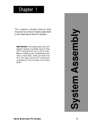
System Assembly Chapter 1 This chapter includes step-by-step instructions on the back panel. Genie Book Size PC System 9 Before installing your motherboard and other components, make sure that they fit in the Genie Book Size PC System. IMPORTANT: The Genie Book Size PC System chassis is suitable only for Flex ATX motherboards up to install components in the case and the I/O connectors correspond to the I/O plate on how to 20cm wide.
System Assembly Chapter 1 This chapter includes step-by-step instructions on the back panel. Genie Book Size PC System 9 Before installing your motherboard and other components, make sure that they fit in the Genie Book Size PC System. IMPORTANT: The Genie Book Size PC System chassis is suitable only for Flex ATX motherboards up to install components in the case and the I/O connectors correspond to the I/O plate on how to 20cm wide.
Installation Guide
Page 13
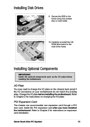
... not match the existing plate. Install the optional components such as the I /O plate before installing the motherboard. I/O Plate You may need to Chapter 2 for instructions on expansion card installation. PCI Expansion Card The chassis can accommodate one expansion card through a... PCI riser card. Refer to change the I/O plate on the chassis back panel if the I /O plate. Genie Book Size PC System 13 Carefully re-install the CDROM drive frame to Chapter 2 for instructions on changing the I /O connectors on each side). 10. ...
... not match the existing plate. Install the optional components such as the I /O plate before installing the motherboard. I/O Plate You may need to Chapter 2 for instructions on expansion card installation. PCI Expansion Card The chassis can accommodate one expansion card through a... PCI riser card. Refer to change the I/O plate on the chassis back panel if the I /O plate. Genie Book Size PC System 13 Carefully re-install the CDROM drive frame to Chapter 2 for instructions on changing the I /O connectors on each side). 10. ...
Installation Guide
Page 15
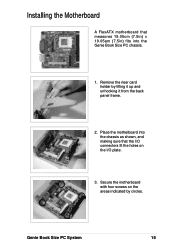
Place the motherboard into the Genie Book Size PC chassis. 1. Installing the Motherboard A FlexATX motherboard that measures 19.05cm (7.5in) x 19.05am (7.5in) fits into the chassis as shown, and making sure that the I /O plate. 3. Remove the riser card holder by circles. Secure the motherboard with four screws on the I /O connectors fit the holes on the areas indicated by lifting it up and unhooking it from the back panel frame. 2. Genie Book Size PC System 15
Place the motherboard into the Genie Book Size PC chassis. 1. Installing the Motherboard A FlexATX motherboard that measures 19.05cm (7.5in) x 19.05am (7.5in) fits into the chassis as shown, and making sure that the I /O plate. 3. Remove the riser card holder by circles. Secure the motherboard with four screws on the I /O connectors fit the holes on the areas indicated by lifting it up and unhooking it from the back panel frame. 2. Genie Book Size PC System 15
Installation Guide
Page 20
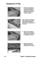
Changing the I /O plate slide in place. 3. Make sure that secure it are tight.) After removing the existing I/O plate, the back panel exposes an opening and sliding it to the left until it to fit your motherboard I /O plate. Detach the I/O plate from the chassis by fitting it to the I/O opening for the new I/O plate to the right. (CAUTION: Be careful when removing the I /O connectors. 2. Install a new I/O plate by sliding it completely fits in behind the securing tabs on the frame. 20 Chapter 2: Optional Procedures The tabs that the I /O Plate 1.
Changing the I /O plate slide in place. 3. Make sure that secure it are tight.) After removing the existing I/O plate, the back panel exposes an opening and sliding it to the left until it to fit your motherboard I /O plate. Detach the I/O plate from the chassis by fitting it to the I/O opening for the new I/O plate to the right. (CAUTION: Be careful when removing the I /O connectors. 2. Install a new I/O plate by sliding it completely fits in behind the securing tabs on the frame. 20 Chapter 2: Optional Procedures The tabs that the I /O Plate 1.
Installation Guide
Page 21
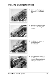
Insert the golden fingers of the PCI expansion card into the riser card slot and push in firmly to access the PCI expansion slot. 2. Lift the card locking tab to seat the card. Remove the expansion slot metal cover by sliding it to the connector on the motherboard. 4. Install the riser card to the right. 3. Installing a PCI Expansion Card 1. Genie Book Size PC System 21
Insert the golden fingers of the PCI expansion card into the riser card slot and push in firmly to access the PCI expansion slot. 2. Lift the card locking tab to seat the card. Remove the expansion slot metal cover by sliding it to the connector on the motherboard. 4. Install the riser card to the right. 3. Installing a PCI Expansion Card 1. Genie Book Size PC System 21


