
User Guide
Page 1
F2A85-V PRO Motherboard
F2A85-V PRO Motherboard
User Guide
Page 3
Contents Safety information vi About this guide vii F2A85-V PRO specifications summary ix Chapter 1: Product introduction 1.1 Welcome 1-1 1.2 Package contents 1-1 1.3 Special features 1-2 1.3.1 Product highlights 1-2 1.3.2 Dual Intelligent Processors 3 with New DIGI+ Power Control 1-2 1.3.3 ASUS Exclusive Features 1-4 1.3.4 ASUS Quiet Thermal Solutions 1-5 1.3.5 ASUS EZ DIY 1-6 Chapter 2: Hardware information 2.1 Before you proceed 2-1 2.2 Motherboard overview 2-2 2.2.1 Motherboard layout 2-2 2.2.2 Accelerated Processing Unit (APU 2-4 2.2.3 System memory 2-5 2.2.4 Expansion...
Contents Safety information vi About this guide vii F2A85-V PRO specifications summary ix Chapter 1: Product introduction 1.1 Welcome 1-1 1.2 Package contents 1-1 1.3 Special features 1-2 1.3.1 Product highlights 1-2 1.3.2 Dual Intelligent Processors 3 with New DIGI+ Power Control 1-2 1.3.3 ASUS Exclusive Features 1-4 1.3.4 ASUS Quiet Thermal Solutions 1-5 1.3.5 ASUS EZ DIY 1-6 Chapter 2: Hardware information 2.1 Before you proceed 2-1 2.2 Motherboard overview 2-2 2.2.1 Motherboard layout 2-2 2.2.2 Accelerated Processing Unit (APU 2-4 2.2.3 System memory 2-5 2.2.4 Expansion...
User Guide
Page 13
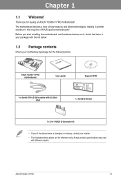
... the items in your package with the list below. 1.2 Package contents Check your retailer. • The illustrated items above are for buying an ASUS® F2A85-V PRO motherboard! ASUS F2A85-V PRO 1-1 Thank you start installing the motherboard, and hardware devices on it another standout in -1 ASUS Q-Connector kit • If any of ASUS quality motherboards! Chapter 1 Chapter 1: Chapter 1 Product introduction 1.1 Welcome!
... the items in your package with the list below. 1.2 Package contents Check your retailer. • The illustrated items above are for buying an ASUS® F2A85-V PRO motherboard! ASUS F2A85-V PRO 1-1 Thank you start installing the motherboard, and hardware devices on it another standout in -1 ASUS Q-Connector kit • If any of ASUS quality motherboards! Chapter 1 Chapter 1: Chapter 1 Product introduction 1.1 Welcome!
User Guide
Page 14
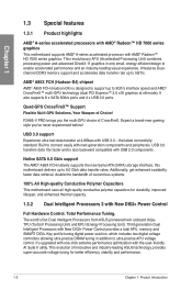
...; Support Flexible Multi-GPU Solutions, Your Weapon of innovative and industry-leading ASUS technology provides super-accurate voltage tuning for durability, improved lifespan, and enhanced thermal... of current bus systems. 100% All High-quality Conductive Polymer Capacitors This motherboard uses all high-quality conductive polymer capacitors for better efficiency, stability and performance...accelerates data transfer rate up to enable accelerated performance and an industry-leading visual experience. F2A85-V PRO brings you 've never experienced before! It also supports 8 x SATA 6Gb/s ...
...; Support Flexible Multi-GPU Solutions, Your Weapon of innovative and industry-leading ASUS technology provides super-accurate voltage tuning for durability, improved lifespan, and enhanced thermal... of current bus systems. 100% All High-quality Conductive Polymer Capacitors This motherboard uses all high-quality conductive polymer capacitors for better efficiency, stability and performance...accelerates data transfer rate up to enable accelerated performance and an industry-leading visual experience. F2A85-V PRO brings you 've never experienced before! It also supports 8 x SATA 6Gb/s ...
User Guide
Page 15
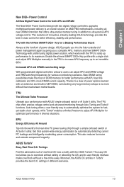
...large memory setups is no more DRAM current capacity. TPU The Ultimate Turbo Processor Unleash your performance with the ASUS TurboV. ASUS TurboV Easy, Real-Time O.C. ASUS F2A85-V PRO 1-3 Thanks to adjust APU Multiplier for optimized performance in diverse situations. Auto tuning offers a user friendly way... APU and DRAM The New DIGI+ Power Control design with two digital voltage controllers upgrades motherboard power delivery to an overall solution on AMD FM2 motherboards, including allnew DRAM controllers that offers ultra-precise memory tuning in addition to overclock without ...
...large memory setups is no more DRAM current capacity. TPU The Ultimate Turbo Processor Unleash your performance with the ASUS TurboV. ASUS TurboV Easy, Real-Time O.C. ASUS F2A85-V PRO 1-3 Thanks to adjust APU Multiplier for optimized performance in diverse situations. Auto tuning offers a user friendly way... APU and DRAM The New DIGI+ Power Control design with two digital voltage controllers upgrades motherboard power delivery to an overall solution on AMD FM2 motherboards, including allnew DRAM controllers that offers ultra-precise memory tuning in addition to overclock without ...
User Guide
Page 17
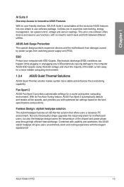
... supervise overclocking, energy management, fan speed control, voltage and sensor readings. ASUS ESD Guards clamp the ESD voltage and shunt the majority of the ESD current away for motherboard users, but also the heatpipe design lowers the temperature of the chipset and... features a 0-dB thermal solution that offers users a noiseless PC environment. ASUS F2A85-V PRO 1-5 Fan Xpert 2 ASUS Fan Xpert 2 provides customizable settings for a cooler and quieter computing environment. With its user-friendly interface, ASUS AI Suite II consolidates all -in-one simple to use functions, with ...
... supervise overclocking, energy management, fan speed control, voltage and sensor readings. ASUS ESD Guards clamp the ESD voltage and shunt the majority of the ESD current away for motherboard users, but also the heatpipe design lowers the temperature of the chipset and... features a 0-dB thermal solution that offers users a noiseless PC environment. ASUS F2A85-V PRO 1-5 Fan Xpert 2 ASUS Fan Xpert 2 provides customizable settings for a cooler and quieter computing environment. With its user-friendly interface, ASUS AI Suite II consolidates all -in-one simple to use functions, with ...
User Guide
Page 19
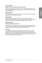
... allows you to connect or disconnect chassis front panel cables in one complete module. ASUS F2A85-V PRO 1-7 ASUS Q-Design ASUS Q-Design enhances your motherboard against Electronic Magnetic Interference (EMI). All of plugging in one easy step with ASUS vision of creating environment-friendly and energyefficient products through product design and innovation to energy consumptions. Chapter 1 CrashFree BIOS...
... allows you to connect or disconnect chassis front panel cables in one complete module. ASUS F2A85-V PRO 1-7 ASUS Q-Design ASUS Q-Design enhances your motherboard against Electronic Magnetic Interference (EMI). All of plugging in one easy step with ASUS vision of creating environment-friendly and energyefficient products through product design and innovation to energy consumptions. Chapter 1 CrashFree BIOS...
User Guide
Page 21
Chapter 2: Chapter 2 Hardware information 2.1 Before you install motherboard components or change any component. • Before handling components, use a grounded wrist strap or touch a safely grounded object or a metal object, such as the power ... power cord is detached from the wall socket before you proceed Take note of the following precautions before touching any motherboard settings. • Unplug the power cord from the power supply. Chapter 2 ASUS F2A85-V PRO 2-1 Failure to do so may cause severe damage to avoid touching the ICs on them due to static electricity...
Chapter 2: Chapter 2 Hardware information 2.1 Before you install motherboard components or change any component. • Before handling components, use a grounded wrist strap or touch a safely grounded object or a metal object, such as the power ... power cord is detached from the wall socket before you proceed Take note of the following precautions before touching any motherboard settings. • Unplug the power cord from the power supply. Chapter 2 ASUS F2A85-V PRO 2-1 Failure to do so may cause severe damage to avoid touching the ICs on them due to static electricity...

User Guide
Page 22
Chapter 2 2.2 Motherboard overview 2.2.1 Motherboard layout 12 KBMS_USB12 SPDIFO _HDMI _DP EATX12V ASM 1445 2 3 24.4cm(9.6in) 45 CPU_FAN EPU CHA_FAN3 EPU_LED DIGI+ DIGI+ 6 EPU 7 MemOK! 8 DRAM_LED DDR3 ...64bit, 240-pin module) DVI_VGA SOCKET FM2 EATXPWR ESATA6G_ USB3_12 1 LAN_USB3_E12 AUDIO RTL 8111F ASM 1042 CHA_FAN1 PCIEX1_1 PCIEX1_2 Lithium Cell CMOS Power PCIEX16_1 F2A85-V PRO ICS 477D CHA_FAN4 SATA6G_7 SATA6G_1 SATA6G_3 SATA6G_5 SATA6G_2 SATA6G_4 SATA6G_6 PCI1 AMD® A85X Super I/O PCIEX16_2 PCI2 ALC PCIEX16_3 892 SPDIF_OUT CHA_FAN2 COM1 AAFP ...
Chapter 2 2.2 Motherboard overview 2.2.1 Motherboard layout 12 KBMS_USB12 SPDIFO _HDMI _DP EATX12V ASM 1445 2 3 24.4cm(9.6in) 45 CPU_FAN EPU CHA_FAN3 EPU_LED DIGI+ DIGI+ 6 EPU 7 MemOK! 8 DRAM_LED DDR3 ...64bit, 240-pin module) DVI_VGA SOCKET FM2 EATXPWR ESATA6G_ USB3_12 1 LAN_USB3_E12 AUDIO RTL 8111F ASM 1042 CHA_FAN1 PCIEX1_1 PCIEX1_2 Lithium Cell CMOS Power PCIEX16_1 F2A85-V PRO ICS 477D CHA_FAN4 SATA6G_7 SATA6G_1 SATA6G_3 SATA6G_5 SATA6G_2 SATA6G_4 SATA6G_6 PCI1 AMD® A85X Super I/O PCIEX16_2 PCI2 ALC PCIEX16_3 892 SPDIF_OUT CHA_FAN2 COM1 AAFP ...
User Guide
Page 24
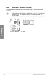
Ensure that you use a APU designed for AMD™ A-Series Accelerated processors. The APU fits in only one correct orientation. DO NOT force the APU into the socket to prevent bending the pins and damaging the APU! F2A85-V PRO F2A85-V PRO CPU socket FM2 Chapter 2 2-4 Chapter 2: Hardware information 2.2.2 Accelerated Processing Unit (APU) This motherboard comes with an FM2 socket designed for the FM2 socket.
Ensure that you use a APU designed for AMD™ A-Series Accelerated processors. The APU fits in only one correct orientation. DO NOT force the APU into the socket to prevent bending the pins and damaging the APU! F2A85-V PRO F2A85-V PRO CPU socket FM2 Chapter 2 2-4 Chapter 2: Hardware information 2.2.2 Accelerated Processing Unit (APU) This motherboard comes with an FM2 socket designed for the FM2 socket.
User Guide
Page 25
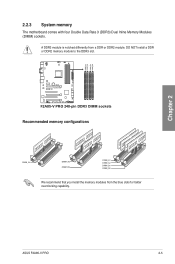
A DDR3 module is notched differently from the blue slots for better overclocking capability. ASUS F2A85-V PRO 2-5 DIMM_A1 DIMM_A2 DIMM_B1 DIMM_B2 Chapter 2 2.2.3 System memory The motherboard comes with four Double Data Rate 3 (DDR3) Dual Inline Memory Modules (DIMM) sockets. DO NOT install a DDR or DDR2 memory module to the DDR3 slot. F2A85-V PRO F2A85-V PRO 240-pin DDR3 DIMM sockets Recommended memory configurations We recommend that you install the memory modules from a DDR or DDR2 module.
A DDR3 module is notched differently from the blue slots for better overclocking capability. ASUS F2A85-V PRO 2-5 DIMM_A1 DIMM_A2 DIMM_B1 DIMM_B2 Chapter 2 2.2.3 System memory The motherboard comes with four Double Data Rate 3 (DDR3) Dual Inline Memory Modules (DIMM) sockets. DO NOT install a DDR or DDR2 memory module to the DDR3 slot. F2A85-V PRO F2A85-V PRO 240-pin DDR3 DIMM sockets Recommended memory configurations We recommend that you install the memory modules from a DDR or DDR2 module.
User Guide
Page 26
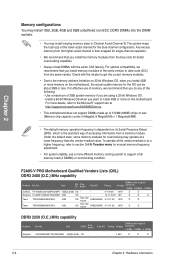
...at the vendor-marked or at a higher frequency, refer to the Microsoft® support site at a lower frequency than the vendor-marked value. F2A85-V PRO Motherboard Qualified Vendors Lists (QVL) DDR3 2400 (O.C.) MHz capability Vendors Part No. Size SS/ Chip DS Brand Chip NO. Chapter 2 Memory configurations You...For system stability, use of memory, we recommend that you install the memory modules from a memory module. For more memory on the motherboard. Check with the same CAS latency. Size SS/DS Chip Brand DIMM socket support Chip NO. Any excess memory from the higher-sized ...
...at the vendor-marked or at a higher frequency, refer to the Microsoft® support site at a lower frequency than the vendor-marked value. F2A85-V PRO Motherboard Qualified Vendors Lists (QVL) DDR3 2400 (O.C.) MHz capability Vendors Part No. Size SS/ Chip DS Brand Chip NO. Chapter 2 Memory configurations You...For system stability, use of memory, we recommend that you install the memory modules from a memory module. For more memory on the motherboard. Check with the same CAS latency. Size SS/DS Chip Brand DIMM socket support Chip NO. Any excess memory from the higher-sized ...
User Guide
Page 33
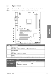
2.2.4 Expansion slots Ensure to do so may cause you physical injury and damage motherboard components. Slot Description 1 PCIe 2.0 x1_1 slot 2 PCIe 2.0 x16_1 slot [navy blue] (single at x16 or dual at x8/x8 mode) 3 PCIe 2.0 x1_2 slot 4 ... VGA configuration Single VGA/PCIe card Dual VGA/PCIe card PCI Express operating mode PCIe 2.0 x16_1 x16 (Recommend for single VGA) x8 PCIe 2.0 x16_2 N/A x8 ASUS F2A85-V PRO 2-13 Chapter 2 1 2 F2A85-V PRO 3 4 5 6 7 Slot No. Failure to unplug the power cord before adding or removing expansion cards. PCIe 2.0 x16_3 slot [black] (at x8 mode)...
2.2.4 Expansion slots Ensure to do so may cause you physical injury and damage motherboard components. Slot Description 1 PCIe 2.0 x1_1 slot 2 PCIe 2.0 x16_1 slot [navy blue] (single at x16 or dual at x8/x8 mode) 3 PCIe 2.0 x1_2 slot 4 ... VGA configuration Single VGA/PCIe card Dual VGA/PCIe card PCI Express operating mode PCIe 2.0 x16_1 x16 (Recommend for single VGA) x8 PCIe 2.0 x16_2 N/A x8 ASUS F2A85-V PRO 2-13 Chapter 2 1 2 F2A85-V PRO 3 4 5 6 7 Slot No. Failure to unplug the power cord before adding or removing expansion cards. PCIe 2.0 x16_3 slot [black] (at x8 mode)...

User Guide
Page 36
... switch until the DRAM_LED starts blinking to boot after turning on the ASUS website at www.asus.com after using the MemOK! If the installed DIMMs still fail to ... reboots when each timing set is tested. function. 2-16 Chapter 2: Hardware information Chapter 2 F2A85-V PRO F2A85-V PRO MemOK! The blinking speed of failsafe settings. switch to enhance system performance. 1. To stop ... DRAM_LED also lights when the DIMM is not properly installed. Replace the DIMMs with the motherboard may cause system boot failure, and the DRAM_LED near the MemOK! MemOK! switch does not...
... switch until the DRAM_LED starts blinking to boot after turning on the ASUS website at www.asus.com after using the MemOK! If the installed DIMMs still fail to ... reboots when each timing set is tested. function. 2-16 Chapter 2: Hardware information Chapter 2 F2A85-V PRO F2A85-V PRO MemOK! The blinking speed of failsafe settings. switch to enhance system performance. 1. To stop ... DRAM_LED also lights when the DIMM is not properly installed. Replace the DIMMs with the motherboard may cause system boot failure, and the DRAM_LED near the MemOK! MemOK! switch does not...
User Guide
Page 40
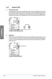
The illustration below shows the location of the onboard LED. This is solved. F2A85-V PRO SB_PWR ON OFF Standby Power Powered Off F2A85-V PRO Onboard LED 2. If an error is found, the LED next to the error device will continue lighting ... cable before removing or plugging in sequence during motherboard booting process. Chapter 2 2.2.7 Onboard LEDs 1. DRAM LED DRAM LED checks the DRAM in any motherboard component. Standby Power LED The motherboard comes with a standby power LED. DRAM LED F2A85-V PRO F2A85-V PRO DRAM LED 2-20 Chapter 2: Hardware information The...
The illustration below shows the location of the onboard LED. This is solved. F2A85-V PRO SB_PWR ON OFF Standby Power Powered Off F2A85-V PRO Onboard LED 2. If an error is found, the LED next to the error device will continue lighting ... cable before removing or plugging in sequence during motherboard booting process. Chapter 2 2.2.7 Onboard LEDs 1. DRAM LED DRAM LED checks the DRAM in any motherboard component. Standby Power LED The motherboard comes with a standby power LED. DRAM LED F2A85-V PRO F2A85-V PRO DRAM LED 2-20 Chapter 2: Hardware information The...
User Guide
Page 42
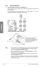
... RSATA_RXP7 GND SATA6G_5 SATA6G_6 GND RSATA_RXP5 RSATA_RXN5 GND RSATA_TXN5 RSATA_TXP5 GND GND RSATA_RXP6 RSATA_RXN6 GND RSATA_TXN6 RSATA_TXP6 GND F2A85-V PRO SATA6G_3 SATA6G_4 GND RSATA_RXP3 RSATA_RXN3 GND RSATA_TXN3 RSATA_TXP3 GND GND RSATA_RXP4 RSATA_RXN4 GND RSATA_TXN4 RSATA_TXP4 GND SATA6G_1 SATA6G_2 ... SATA Configuration for details. • Before creating a RAID set, refer to section 4.4 RAID configurations or the manual bundled in the motherboard support DVD. • When using NCQ, set using Windows ® XP SP3 or later versions. 2-22 Chapter 2: Hardware information If...
... RSATA_RXP7 GND SATA6G_5 SATA6G_6 GND RSATA_RXP5 RSATA_RXN5 GND RSATA_TXN5 RSATA_TXP5 GND GND RSATA_RXP6 RSATA_RXN6 GND RSATA_TXN6 RSATA_TXP6 GND F2A85-V PRO SATA6G_3 SATA6G_4 GND RSATA_RXP3 RSATA_RXN3 GND RSATA_TXN3 RSATA_TXP3 GND GND RSATA_RXP4 RSATA_RXN4 GND RSATA_TXN4 RSATA_TXP4 GND SATA6G_1 SATA6G_2 ... SATA Configuration for details. • Before creating a RAID set, refer to section 4.4 RAID configurations or the manual bundled in the motherboard support DVD. • When using NCQ, set using Windows ® XP SP3 or later versions. 2-22 Chapter 2: Hardware information If...
User Guide
Page 43
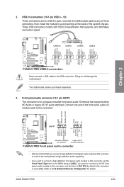
...NC MIC2 MICPWR Line out_R NC Line out_L PORT1 L PORT1 R PORT2 R SENSE_SEND PORT2 L F2A85-V PRO AAFP PIN 1 HD-audio-compliant Legacy AC'97 pin definition compliant definition F2A85-V PRO Front panel audio connector • We recommend that supports up to 480 Mbps connection speed....module to this connector, set the item to [HD]. ASUS F2A85-V PRO 2-23 These USB connectors comply with USB 2.0 specification that you connect a high-definition front panel audio module to this connector to avail of the motherboard's high-definition audio capability. • If you want ...
...NC MIC2 MICPWR Line out_R NC Line out_L PORT1 L PORT1 R PORT2 R SENSE_SEND PORT2 L F2A85-V PRO AAFP PIN 1 HD-audio-compliant Legacy AC'97 pin definition compliant definition F2A85-V PRO Front panel audio connector • We recommend that supports up to 480 Mbps connection speed....module to this connector, set the item to [HD]. ASUS F2A85-V PRO 2-23 These USB connectors comply with USB 2.0 specification that you connect a high-definition front panel audio module to this connector to avail of the motherboard's high-definition audio capability. • If you want ...
User Guide
Page 44
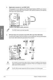
... D CHA_FAN4 CHA FAN DC Mode CHA FAN IN CHA FAN PWR GND E CHA_FAN2 GND CHA FAN PWR CHA FAN IN CHA FAN DC Mode E F2A85-V PRO Fan connectors Do not forget to connect the fan cables to a slot opening at the back of the system chassis. +5V SPDIFOUT GND Chapter... 2 F2A85-V PRO SPDIF_OUT F2A85-V PRO Digital audio connector The S/PDIF module is for an additional Sony/Philips Digital Interface (S/PDIF) port. Do not place jumper caps on the motherboard, ensuring that the black wire of each cable matches the ground pin of...
... D CHA_FAN4 CHA FAN DC Mode CHA FAN IN CHA FAN PWR GND E CHA_FAN2 GND CHA FAN PWR CHA FAN IN CHA FAN DC Mode E F2A85-V PRO Fan connectors Do not forget to connect the fan cables to a slot opening at the back of the system chassis. +5V SPDIFOUT GND Chapter... 2 F2A85-V PRO SPDIF_OUT F2A85-V PRO Digital audio connector The S/PDIF module is for an additional Sony/Philips Digital Interface (S/PDIF) port. Do not place jumper caps on the motherboard, ensuring that the black wire of each cable matches the ground pin of...
User Guide
Page 46
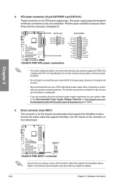
...pin EATX12 V power plug; Refer to the Recommended Power Supply Wattage Calculator at http://support.asus.com/ PowerSupplyCalculator/PSCalculator.aspx?SLanguage=en-us for details. 2-26 Chapter 2: Hardware information ...not boot. • We recommend that came with more power-consuming devices. F2A85-V PRO F2A85-V PRO DRCT connector Ensure that your system, refer to the technical documentation that you use...EATXPWR; 8-pin EATX12V) These connectors are designed to this connector on the motherboard. Connect the button cable that supports the DirectKey function. The power supply ...
...pin EATX12 V power plug; Refer to the Recommended Power Supply Wattage Calculator at http://support.asus.com/ PowerSupplyCalculator/PSCalculator.aspx?SLanguage=en-us for details. 2-26 Chapter 2: Hardware information ...not boot. • We recommend that came with more power-consuming devices. F2A85-V PRO F2A85-V PRO DRCT connector Ensure that your system, refer to the technical documentation that you use...EATXPWR; 8-pin EATX12V) These connectors are designed to this connector on the motherboard. Connect the button cable that supports the DirectKey function. The power supply ...
User Guide
Page 53
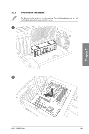
The motherboard layout may vary with models, but the installation steps remain the same. 1 2 Chapter 2 ASUS F2A85-V PRO 2-33 2.3.5 Motherboard installation The diagrams in this section are for reference only.
The motherboard layout may vary with models, but the installation steps remain the same. 1 2 Chapter 2 ASUS F2A85-V PRO 2-33 2.3.5 Motherboard installation The diagrams in this section are for reference only.


