
F2A85-M LE User's Manual
Page 12
... AMD® A85X SATA6G_4 SATA6G_3 SATA6G_5 SATA6G_6 SATA6G_7 ALC 887 SPDIF_OUT AAFP PCIEX16_2 LPT USB910 USB78 USB56 USB3_34 CLRTC SPEAKER 64Mb SATA6G_2 BIOS SATA6G_1 F_PANEL ASUS F2A85-M LE motherboard User Guide 2 x Serial ATA 6.0 Gb/s cables 1 x I/O-Shield User Guide Support DVD • If any of the above items is damaged or missing, contact your...
... AMD® A85X SATA6G_4 SATA6G_3 SATA6G_5 SATA6G_6 SATA6G_7 ALC 887 SPDIF_OUT AAFP PCIEX16_2 LPT USB910 USB78 USB56 USB3_34 CLRTC SPEAKER 64Mb SATA6G_2 BIOS SATA6G_1 F_PANEL ASUS F2A85-M LE motherboard User Guide 2 x Serial ATA 6.0 Gb/s cables 1 x I/O-Shield User Guide Support DVD • If any of the above items is damaged or missing, contact your...

F2A85-M LE User's Manual
Page 13
... 2.0. AMD® CrossFireX™ Technology AMD's CrossFireX™ boosts image quality along with rendering speed, eliminating the need to scale down screen resolution to 5GT/s. ASUS F2A85-M LE 1-1 Native SATA 6.0 Gb/s support With AMD® A85X FCH natively support for durability, improved lifespan, and enhanced thermal capacity. Adjust your display configurations, experiment with...
... 2.0. AMD® CrossFireX™ Technology AMD's CrossFireX™ boosts image quality along with rendering speed, eliminating the need to scale down screen resolution to 5GT/s. ASUS F2A85-M LE 1-1 Native SATA 6.0 Gb/s support With AMD® A85X FCH natively support for durability, improved lifespan, and enhanced thermal capacity. Adjust your display configurations, experiment with...

F2A85-M LE User's Manual
Page 15
... motherboard from damage caused by power surges from a USB storage device that allows you to open the system chassis and clear the RTC data. ASUS F2A85-M LE 1-3 ASUS Fan Xpert ASUS Fan Xpert intelligently allows you to adjust the CPU fan speed based on different ambient temperatures, resulting to personalize your favorite photos into 256...
... motherboard from damage caused by power surges from a USB storage device that allows you to open the system chassis and clear the RTC data. ASUS F2A85-M LE 1-3 ASUS Fan Xpert ASUS Fan Xpert intelligently allows you to adjust the CPU fan speed based on different ambient temperatures, resulting to personalize your favorite photos into 256...
F2A85-M LE User's Manual
Page 17
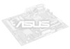
DO NOT overtighten the screws! F2A85-M LE ASUS F2A85-M LE 1-5 1.3 Motherboard overview 1.3.1 Placement direction When installing the motherboard, ensure that you place it into the holes indicated by circles to secure the motherboard to the rear part of the chassis. Doing so can damage the motherboard. Place this side towards the rear of the chassis as indicated in the image below. 1.3.2 Screw holes Place six screws into the chassis in the correct orientation. The edge with external ports goes to the chassis.
DO NOT overtighten the screws! F2A85-M LE ASUS F2A85-M LE 1-5 1.3 Motherboard overview 1.3.1 Placement direction When installing the motherboard, ensure that you place it into the holes indicated by circles to secure the motherboard to the rear part of the chassis. Doing so can damage the motherboard. Place this side towards the rear of the chassis as indicated in the image below. 1.3.2 Screw holes Place six screws into the chassis in the correct orientation. The edge with external ports goes to the chassis.

F2A85-M LE User's Manual
Page 19
...™ HD 7000 series graphics. SATA 6.0Gb/s connectors (7-pin SATA6G_1~7) 7. USB 3.0 connector (20-1 pin USB3_34) 12. The APU fits in only one correct orientation. F2A85-M LE F2A85-M LE APU socket FM2 ASUS F2A85-M LE 1-7 Serial port connector (10-1 pin COM) 3. Speaker connector (4-pin SPEAKER) 9. Standby power LED (SB_PWR) 11. Digital audio connector (4-1 pin SPDIF_OUT) Page 1-23 1-29...
...™ HD 7000 series graphics. SATA 6.0Gb/s connectors (7-pin SATA6G_1~7) 7. USB 3.0 connector (20-1 pin USB3_34) 12. The APU fits in only one correct orientation. F2A85-M LE F2A85-M LE APU socket FM2 ASUS F2A85-M LE 1-7 Serial port connector (10-1 pin COM) 3. Speaker connector (4-pin SPEAKER) 9. Standby power LED (SB_PWR) 11. Digital audio connector (4-1 pin SPDIF_OUT) Page 1-23 1-29...
F2A85-M LE User's Manual
Page 21
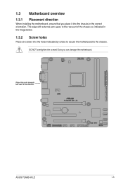
To install the APU heatsink and fan assembly 1 2 3 4 5 ASUS F2A85-M LE 1-9 1.4.2 APU heatsink and fan assembly installation Apply the Thermal Interface Material to the APU heatsink and APU before you install the heatsink and fan if necessary.
To install the APU heatsink and fan assembly 1 2 3 4 5 ASUS F2A85-M LE 1-9 1.4.2 APU heatsink and fan assembly installation Apply the Thermal Interface Material to the APU heatsink and APU before you install the heatsink and fan if necessary.

F2A85-M LE User's Manual
Page 23
DDR3 modules are developed for better performance with two Double Data Rate 3 (DDR3) Dual Inline Memory Modules (DIMM) sockets. The figure illustrates the location of the DDR3 DIMM sockets: DIMM_A1 DIMM_B1 F2A85-M LE Channel Channel A Channel B F2A85-M LE 240-pin DDR3 DIMM sockets Sockets DIMM_A1 DIMM_B1 ASUS F2A85-M LE 1-11 1.5 System memory 1.5.1 Overview This motherboard comes with less power consumption. A DDR3 module has the same physical dimensions as a DDR2 DIMM but is notched differently to prevent installation on a DDR2 DIMM socket.
DDR3 modules are developed for better performance with two Double Data Rate 3 (DDR3) Dual Inline Memory Modules (DIMM) sockets. The figure illustrates the location of the DDR3 DIMM sockets: DIMM_A1 DIMM_B1 F2A85-M LE Channel Channel A Channel B F2A85-M LE 240-pin DDR3 DIMM sockets Sockets DIMM_A1 DIMM_B1 ASUS F2A85-M LE 1-11 1.5 System memory 1.5.1 Overview This motherboard comes with less power consumption. A DDR3 module has the same physical dimensions as a DDR2 DIMM but is notched differently to prevent installation on a DDR2 DIMM socket.
F2A85-M LE User's Manual
Page 29
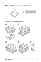
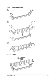
1.5.3 1 Installing a DIMM 2 3 To remove a DIMM B A A ASUS F2A85-M LE 1-17
1.5.3 1 Installing a DIMM 2 3 To remove a DIMM B A A ASUS F2A85-M LE 1-17

F2A85-M LE User's Manual
Page 31
.... • We recommend that you provide sufficient power when running CrossFireX™ mode. OnChip USB EHCI 1/2/3 - IRQ assignments for this motherboard A B C D E F G H PCIEx16_1 - - HD audio shared - - - - - - - ASUS F2A85-M LE 1-19 VGA configuration Single VGA/PCIe card Dual VGA/PCIe card PCI Express operating mode PCIe x16_1 x16 (Recommended for single VGA card) x16 PCIe...
.... • We recommend that you provide sufficient power when running CrossFireX™ mode. OnChip USB EHCI 1/2/3 - IRQ assignments for this motherboard A B C D E F G H PCIEx16_1 - - HD audio shared - - - - - - - ASUS F2A85-M LE 1-19 VGA configuration Single VGA/PCIe card Dual VGA/PCIe card PCI Express operating mode PCIe x16_1 x16 (Recommended for single VGA card) x16 PCIe...
F2A85-M LE User's Manual
Page 33
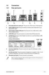
... blue). This port connects an external audio output device via an optical S/PDIF cable. 3. This port connects to an external Serial ATA hard disk drive. 5. ASUS F2A85-M LE 1-21 Refer to a Local Area Network (LAN) through a network hub. LAN port LED indications Activity/Link LED Status Description OFF No link ORANGE Linked BLINKING...
... blue). This port connects an external audio output device via an optical S/PDIF cable. 3. This port connects to an external Serial ATA hard disk drive. 5. ASUS F2A85-M LE 1-21 Refer to a Local Area Network (LAN) through a network hub. LAN port LED indications Activity/Link LED Status Description OFF No link ORANGE Linked BLINKING...

F2A85-M LE User's Manual
Page 35
... connectors. • The CPU_FAN connector supports a CPU fan of maximum 2A (24 W) fan power. • Only the CPU_FAN connector support the ASUS Fan Xpert feature. • If you install two VGA cards, we recommend that the black wire of each cable matches the ground pin of the...cables to the motherboard connector labeled CHA_FAN for better thermal environment. Insufficient air flow inside the system may damage the motherboard components. ASUS F2A85-M LE 1-23 DO NOT place jumper caps on the motherboard, ensuring that you plug the rear chassis fan cable to the fan connectors.
... connectors. • The CPU_FAN connector supports a CPU fan of maximum 2A (24 W) fan power. • Only the CPU_FAN connector support the ASUS Fan Xpert feature. • If you install two VGA cards, we recommend that the black wire of each cable matches the ground pin of the...cables to the motherboard connector labeled CHA_FAN for better thermal environment. Insufficient air flow inside the system may damage the motherboard components. ASUS F2A85-M LE 1-23 DO NOT place jumper caps on the motherboard, ensuring that you plug the rear chassis fan cable to the fan connectors.

F2A85-M LE User's Manual
Page 37
... RAID 5, or RAID 10 configuration through the onboard controller. ASUS F2A85-M LE 1-25 SATA6G_4 SATA6G_7 GND RSATA_TXP7 RSATA_TXN7 GND RSATA_RXN7 RSATA_RXP7 GND GND RSATA_RXP4 RSATA_RXN4 GND RSATA_TXN4 RSATA_TXP4 GND F2A85-M LE SATA6G_3 SATA6G_2 SATA6G_1 GND RSATA_RXP2 RSATA_RXN2 GND RSATA_TXN2 RSATA_TXP2 GND GND ... GND RSATA_RXN6 RSATA_RXP6 GND SATA6G_5 GND RSATA_TXP5 RSATA_TXN5 GND RSATA_RXN5 RSATA_RXP5 GND GND RSATA_RXP1 RSATA_RXN1 GND RSATA_TXN1 RSATA_TXP1 GND F2A85-M LE SATA 6.0Gb/s connectors • These connectors are for the Serial ATA 6.0 Gb/s signal cables for Serial...
... RAID 5, or RAID 10 configuration through the onboard controller. ASUS F2A85-M LE 1-25 SATA6G_4 SATA6G_7 GND RSATA_TXP7 RSATA_TXN7 GND RSATA_RXN7 RSATA_RXP7 GND GND RSATA_RXP4 RSATA_RXN4 GND RSATA_TXN4 RSATA_TXP4 GND F2A85-M LE SATA6G_3 SATA6G_2 SATA6G_1 GND RSATA_RXP2 RSATA_RXN2 GND RSATA_TXN2 RSATA_TXP2 GND GND ... GND RSATA_RXN6 RSATA_RXP6 GND SATA6G_5 GND RSATA_TXP5 RSATA_TXN5 GND RSATA_RXN5 RSATA_RXP5 GND GND RSATA_RXP1 RSATA_RXN1 GND RSATA_TXN1 RSATA_TXP1 GND F2A85-M LE SATA 6.0Gb/s connectors • These connectors are for the Serial ATA 6.0 Gb/s signal cables for Serial...

F2A85-M LE User's Manual
Page 39
... MIC2 MICPWR Line out_R NC Line out_L PORT1 L PORT1 R PORT2 R SENSE_SEND PORT2 L F2A85-M LE HD-audio-compliant Legacy AC'97 pin definition compliant definition F2A85-M LE Front panel audio connector • We recommend that supports either High Definition Audio or AC`...(4-1 pin SPDIF_OUT) This connector is for an additional Sony/Philips Digital Interface (S/PDIF) port. F2A85-M LE SPDIF_OUT F2A85-M LE Digital audio connector The S/PDIF module is purchased separately. ASUS F2A85-M LE 1-27 Front panel audio connector (10-1 pin AAFP) This connector is for a chassis-mounted...
... MIC2 MICPWR Line out_R NC Line out_L PORT1 L PORT1 R PORT2 R SENSE_SEND PORT2 L F2A85-M LE HD-audio-compliant Legacy AC'97 pin definition compliant definition F2A85-M LE Front panel audio connector • We recommend that supports either High Definition Audio or AC`...(4-1 pin SPDIF_OUT) This connector is for an additional Sony/Philips Digital Interface (S/PDIF) port. F2A85-M LE SPDIF_OUT F2A85-M LE Digital audio connector The S/PDIF module is purchased separately. ASUS F2A85-M LE 1-27 Front panel audio connector (10-1 pin AAFP) This connector is for a chassis-mounted...
F2A85-M LE User's Manual
Page 41
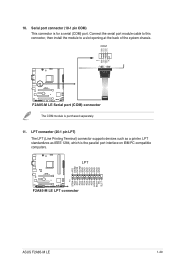
... ERR# INIT# SLIN# GND GND GND GND GND GND GND GND F2A85-M LE LPT PIN 1 STB# PD0 PD1 PD2 PD3 PD4 PD5 PD6 PD7 ACK# BUSY PE SLCT F2A85-M LE LPT connector ASUS F2A85-M LE 1-29 COM PIN 1 RXD DTR DSR CTS DCD TXD GND RTS RI F2A85-M LE F2A85-M LE Serial port (COM) connector The COM module is for a serial...
... ERR# INIT# SLIN# GND GND GND GND GND GND GND GND F2A85-M LE LPT PIN 1 STB# PD0 PD1 PD2 PD3 PD4 PD5 PD6 PD7 ACK# BUSY PE SLCT F2A85-M LE LPT connector ASUS F2A85-M LE 1-29 COM PIN 1 RXD DTR DSR CTS DCD TXD GND RTS RI F2A85-M LE F2A85-M LE Serial port (COM) connector The COM module is for a serial...

F2A85-M LE User's Manual
Page 44
... the latest BIOS, and then press . 5. Enter the Advanced Mode of updating itself through the Internet. Updating from the ASUS website at www.asus.com. Before you wish to prevent system boot failure! 2-2 ASUS F2A85-M LE To update the BIOS using an OS‑based utility. From the FTP site, select the BIOS version that...
... the latest BIOS, and then press . 5. Enter the Advanced Mode of updating itself through the Internet. Updating from the ASUS website at www.asus.com. Before you wish to prevent system boot failure! 2-2 ASUS F2A85-M LE To update the BIOS using an OS‑based utility. From the FTP site, select the BIOS version that...

F2A85-M LE User's Manual
Page 46
.... Do not save them on the USB flash drive. Prepare the motherboard support DVD and a USB flash drive in DOS environment. C:\>d: D:\> 2-4 ASUS F2A85-M LE Boot your computer. Insert the USB flash drive with the latest BIOS file and BIOS Updater to FreeDOS (http://www.freedos.org)! The succeeding utility...process. This utility also allows you to copy the current BIOS file that you to show the BIOS Boot Device Select Menu. When the ASUS Logo appears, press to update BIOS in FAT32/16 format and single partition. 2. Insert the support DVD into the optical drive and ...
.... Do not save them on the USB flash drive. Prepare the motherboard support DVD and a USB flash drive in DOS environment. C:\>d: D:\> 2-4 ASUS F2A85-M LE Boot your computer. Insert the USB flash drive with the latest BIOS file and BIOS Updater to FreeDOS (http://www.freedos.org)! The succeeding utility...process. This utility also allows you to copy the current BIOS file that you to show the BIOS Boot Device Select Menu. When the ASUS Logo appears, press to update BIOS in FAT32/16 format and single partition. 2. Insert the support DVD into the optical drive and ...

F2A85-M LE User's Manual
Page 48
... can change modes from the Exit menu or from the operating system. • The BIOS setup screens shown in the EZ Mode/Advanced Mode screen. 2-6 ASUS F2A85-M LE If the system becomes unstable after changing any BIOS settings, load the default settings to your data or system. See section 2.9 Exit Menu. • If...
... can change modes from the Exit menu or from the operating system. • The BIOS setup screens shown in the EZ Mode/Advanced Mode screen. 2-6 ASUS F2A85-M LE If the system becomes unstable after changing any BIOS settings, load the default settings to your data or system. See section 2.9 Exit Menu. • If...
F2A85-M LE User's Manual
Page 50
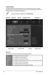
... an example of the screen has the following sections for special functions For selecting the exit options and loading default settings 2-8 ASUS F2A85-M LE To access the EZ Mode, click Exit, then select ASUS EZ Mode. Advanced Mode The Advanced Mode provides advanced options for experienced end-users to the following main items: Main...
... an example of the screen has the following sections for special functions For selecting the exit options and loading default settings 2-8 ASUS F2A85-M LE To access the EZ Mode, click Exit, then select ASUS EZ Mode. Advanced Mode The Advanced Mode provides advanced options for experienced end-users to the following main items: Main...
F2A85-M LE User's Manual
Page 52
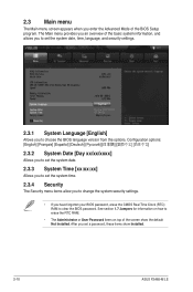
... you set the system date, time, language, and security settings. 2.3.1 System Language [English] Allows you enter the Advanced Mode of the screen show Installed. 2-10 ASUS F2A85-M LE See section 1.7 Jumpers for information on how to erase the RTC RAM. • The Administrator or User Password items on top of the BIOS Setup...
... you set the system date, time, language, and security settings. 2.3.1 System Language [English] Allows you enter the Advanced Mode of the screen show Installed. 2-10 ASUS F2A85-M LE See section 1.7 Jumpers for information on how to erase the RTC RAM. • The Administrator or User Password items on top of the BIOS Setup...
F2A85-M LE User's Manual
Page 54
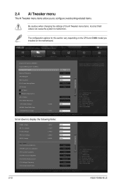
... will be auto-adjusted. →←: Select Screen ↑↓: Select Item Enter: Select +/-: Change Opt. EFI BIOS Utility - Copyright (C) 2012 American Megatrends, Inc. 2-12 ASUS F2A85-M LE Scroll down to malfunction. 2.4 Ai Tweaker menu The Ai Tweaker menu items allow you installed on the motherboard. The configuration options for this section vary...
... will be auto-adjusted. →←: Select Screen ↑↓: Select Item Enter: Select +/-: Change Opt. EFI BIOS Utility - Copyright (C) 2012 American Megatrends, Inc. 2-12 ASUS F2A85-M LE Scroll down to malfunction. 2.4 Ai Tweaker menu The Ai Tweaker menu items allow you installed on the motherboard. The configuration options for this section vary...


