F2A55-M LK2 User's Manual
Page 10
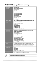
... features Back Panel I/O ports Internal I/O connectors / buttons / switches BIOS Support DVD Form factor ASUS DIGI+ VRM ASUS 3+2 Phase Power Design Network iControl ASUS EPU ASUS AI Suite II ASUS UEFI BIOS EZ Mode ASUS Anti-Surge Protection ASUS Fan Xpert ASUS CrashFree BIOS 3 ASUS EZ Flash 2 ASUS MyLogo 2™ 100% All high quality conductive polymer (F2A55-M LK2 PLUS only) 1 x PS/2 mouse port (green) 1 x PS/2 keyboard port...
... features Back Panel I/O ports Internal I/O connectors / buttons / switches BIOS Support DVD Form factor ASUS DIGI+ VRM ASUS 3+2 Phase Power Design Network iControl ASUS EPU ASUS AI Suite II ASUS UEFI BIOS EZ Mode ASUS Anti-Surge Protection ASUS Fan Xpert ASUS CrashFree BIOS 3 ASUS EZ Flash 2 ASUS MyLogo 2™ 100% All high quality conductive polymer (F2A55-M LK2 PLUS only) 1 x PS/2 mouse port (green) 1 x PS/2 keyboard port...
F2A55-M LK2 User's Manual
Page 11
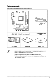
... EATXPWR LAN1_USB12 AUDIO CHA_FAN F2A55-M LK2 PLUS RTL 8111F PCIEX16 PCIEX1_1 Lithium Cell CMOS Power ALC887 Super I/O PCI1 SB_PWR SPDIF_OUTCOM1USBPW5-8 USB78 AAFP AMD® A55 SATA3G_1 SATA3G_2 SPEAKER CLRTC USB56 32Mb BIOS SATA3G_3 SATA3G_4 F_PANEL ASUS F2A55-M LK2 Series motherboard User Guide 2 x Serial ATA 3.0 Gb/s cables 1 x I/O Shield User Guide Support DVD • F2A55-M LK2 Series motherboards include F2A55-M LK2 PLUS and F2A55-M LK2 models.
... EATXPWR LAN1_USB12 AUDIO CHA_FAN F2A55-M LK2 PLUS RTL 8111F PCIEX16 PCIEX1_1 Lithium Cell CMOS Power ALC887 Super I/O PCI1 SB_PWR SPDIF_OUTCOM1USBPW5-8 USB78 AAFP AMD® A55 SATA3G_1 SATA3G_2 SPEAKER CLRTC USB56 32Mb BIOS SATA3G_3 SATA3G_4 F_PANEL ASUS F2A55-M LK2 Series motherboard User Guide 2 x Serial ATA 3.0 Gb/s cables 1 x I/O Shield User Guide Support DVD • F2A55-M LK2 Series motherboards include F2A55-M LK2 PLUS and F2A55-M LK2 models.
F2A55-M LK2 User's Manual
Page 18
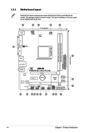
The package contents vary from models. The layout illustrations in this user guide are for F2A55-M LK2 PLUS only. 1 KBMS 2 3 4 5 17.3cm(6.8in) ATX12V DIGI +VRM CPU_FAN DDR3 DIMM_A1 (64bit, 240-pin module) DDR3 DIMM_B1 (64bit, 240-...DVI 16 KBPWR USBPW1-4 SOCKET FM2 22.6cm(8.9in) 1 USB34 EATXPWR LAN1_USB12 AUDIO CHA_FAN F2A55-M LK2 PLUS RTL 8111F PCIEX16 PCIEX1_1 Lithium Cell CMOS Power SATA3G_1 AMD® A55 SATA3G_2 6 ALC887 Super I/O PCI1 32Mb BIOS SB_PWR SPDIF_OUTCOM1USBPW5-8 USB78 SPEAKER CLRTC USB56 SATA3G_3 SATA3G_4 7 AAFP F_PANEL 15 14 13 12 11...
The package contents vary from models. The layout illustrations in this user guide are for F2A55-M LK2 PLUS only. 1 KBMS 2 3 4 5 17.3cm(6.8in) ATX12V DIGI +VRM CPU_FAN DDR3 DIMM_A1 (64bit, 240-pin module) DDR3 DIMM_B1 (64bit, 240-...DVI 16 KBPWR USBPW1-4 SOCKET FM2 22.6cm(8.9in) 1 USB34 EATXPWR LAN1_USB12 AUDIO CHA_FAN F2A55-M LK2 PLUS RTL 8111F PCIEX16 PCIEX1_1 Lithium Cell CMOS Power SATA3G_1 AMD® A55 SATA3G_2 6 ALC887 Super I/O PCI1 32Mb BIOS SB_PWR SPDIF_OUTCOM1USBPW5-8 USB78 SPEAKER CLRTC USB56 SATA3G_3 SATA3G_4 7 AAFP F_PANEL 15 14 13 12 11...
F2A55-M LK2 User's Manual
Page 31
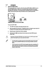
... You do not help, remove the onboard battery and move the cap back to default values. ASUS F2A55-M LK2 Series 1-19 Clear RTC RAM (CLRTC) This jumper allows you to overclocking, use the CPU ...passwords. The onboard button cell battery powers the RAM data in CMOS. F2A55-M LK2 PLUS CLRTC 12 23 Normal (Default) Clear RTC F2A55-M LK2 PLUS Clear RTC RAM To erase the RTC RAM: 1. Move the jumper...hangs due to reenter data. Shut down the key during the boot process and enter BIOS setup to overclocking. You can automatically reset parameter settings to pins 1-2. 3. Plug the ...
... You do not help, remove the onboard battery and move the cap back to default values. ASUS F2A55-M LK2 Series 1-19 Clear RTC RAM (CLRTC) This jumper allows you to overclocking, use the CPU ...passwords. The onboard button cell battery powers the RAM data in CMOS. F2A55-M LK2 PLUS CLRTC 12 23 Normal (Default) Clear RTC F2A55-M LK2 PLUS Clear RTC RAM To erase the RTC RAM: 1. Move the jumper...hangs due to reenter data. Shut down the key during the boot process and enter BIOS setup to overclocking. You can automatically reset parameter settings to pins 1-2. 3. Plug the ...

F2A55-M LK2 User's Manual
Page 32
...BIOS. otherwise, the system would not power up the computer from S3 and S4 sleep modes (no power to wake up . • The total current consumed must NOT exceed the power supply capability (+5VSB) whether under normal condition or in reduced power mode). USBPW1-4 12 23 +5V +5VSB (Default) F2A55-M LK2 PLUS... USBPW5-8 12 23 +5V +5VSB (Default) F2A55-M LK2 PLUS USB Device Wake Up • The USB device wake-up feature requires a power supply that can wake up...
...BIOS. otherwise, the system would not power up the computer from S3 and S4 sleep modes (no power to wake up . • The total current consumed must NOT exceed the power supply capability (+5VSB) whether under normal condition or in reduced power mode). USBPW1-4 12 23 +5V +5VSB (Default) F2A55-M LK2 PLUS... USBPW5-8 12 23 +5V +5VSB (Default) F2A55-M LK2 PLUS USB Device Wake Up • The USB device wake-up feature requires a power supply that can wake up...
F2A55-M LK2 User's Manual
Page 36
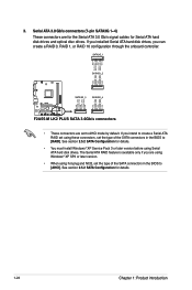
...RSATA_TXN3 GND RSATA_RXN3 RSATA_RXP3 GND GND RSATA_TXP4 RSATA_TXN4 GND RSATA_RXN4 RSATA_RXP4 GND F2A55-M LK2 PLUS SATA3G_3 SATA3G_4 F2A55-M LK2 PLUS SATA 3.0Gb/s connectors • These connectors are set the type of the SATA connectors in the BIOS to AHCI mode by default. The Serial ATA RAID feature is...drives, you intend to create a Serial ATA RAID set using hot-plug and NCQ, set the type of the SATA connectors in the BIOS to [AHCI]. See section 2.5.2 SATA Configuration for details. 1-24 Chapter 1: Product introduction See section 2.5.2 SATA Configuration for details. &#...
...RSATA_TXN3 GND RSATA_RXN3 RSATA_RXP3 GND GND RSATA_TXP4 RSATA_TXN4 GND RSATA_RXN4 RSATA_RXP4 GND F2A55-M LK2 PLUS SATA3G_3 SATA3G_4 F2A55-M LK2 PLUS SATA 3.0Gb/s connectors • These connectors are set the type of the SATA connectors in the BIOS to AHCI mode by default. The Serial ATA RAID feature is...drives, you intend to create a Serial ATA RAID set using hot-plug and NCQ, set the type of the SATA connectors in the BIOS to [AHCI]. See section 2.5.2 SATA Configuration for details. 1-24 Chapter 1: Product introduction See section 2.5.2 SATA Configuration for details. &#...
F2A55-M LK2 User's Manual
Page 38
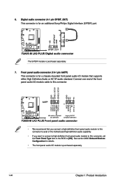
Front panel audio connector (10-1 pin AAFP) This connector is for an additional Sony/Philips Digital Interface (S/PDIF) port. +5V SPDIFOUT GND F2A55-M LK2 PLUS SPDIF_OUT F2A55-M LK2 PLUS Digital audio connector The S/PDIF module is purchased separately. 1-26 Chapter 1: Product introduction Connect one end of the motherboard high-definition audio capability. • If ... audio module to this connector to avail of the front panel audio I/O module cable to this connector, set the Front Panel Type item in the BIOS to this connector.
Front panel audio connector (10-1 pin AAFP) This connector is for an additional Sony/Philips Digital Interface (S/PDIF) port. +5V SPDIFOUT GND F2A55-M LK2 PLUS SPDIF_OUT F2A55-M LK2 PLUS Digital audio connector The S/PDIF module is purchased separately. 1-26 Chapter 1: Product introduction Connect one end of the motherboard high-definition audio capability. • If ... audio module to this connector to avail of the front panel audio I/O module cable to this connector, set the Front Panel Type item in the BIOS to this connector.
F2A55-M LK2 User's Manual
Page 43
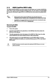
..., the utility reads the BIOS file and enters ASUS EZ Flash 2 utility automatically. 4. To ensure system compatibility and stability, we recommend that you to enter BIOS Setup to load default BIOS values. The utility automatically checks the devices for F2A55-M LK2 PLUS). • The BIOS file in the removable device into F2A5MLK2.CAP (for F2A55-M LK2) or F2A5MK2P.CAP (for...
..., the utility reads the BIOS file and enters ASUS EZ Flash 2 utility automatically. 4. To ensure system compatibility and stability, we recommend that you to enter BIOS Setup to load default BIOS values. The utility automatically checks the devices for F2A55-M LK2 PLUS). • The BIOS file in the removable device into F2A5MLK2.CAP (for F2A55-M LK2) or F2A5MK2P.CAP (for...
F2A55-M LK2 User's Manual
Page 45
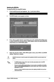
... version 1.30 or later, the utility automatically exits to the DOS prompt after updating the BIOS file if you to section 2.9 Exit menu for DOS V1.30 Current ROM BOARD: F2A55-M LK2 PLUS VER: 0201 DATE: 07/13/2012 Update ROM BOARD: Unknown VER: Unknown DATE: Unknown PATH: A:\ A: F2A5MKP2....CAP 8390656 2012-07-13 17:30:48 Note [Enter] Select or Load [Up/Down/Home/End] Move [Tab] Switch [B] Backup [V] Drive Info [Esc] Exit 3. The BIOS Updater screen...
... version 1.30 or later, the utility automatically exits to the DOS prompt after updating the BIOS file if you to section 2.9 Exit menu for DOS V1.30 Current ROM BOARD: F2A55-M LK2 PLUS VER: 0201 DATE: 07/13/2012 Update ROM BOARD: Unknown VER: Unknown DATE: Unknown PATH: A:\ A: F2A5MKP2....CAP 8390656 2012-07-13 17:30:48 Note [Enter] Select or Load [Up/Down/Home/End] Move [Tab] Switch [B] Backup [V] Drive Info [Esc] Exit 3. The BIOS Updater screen...

